charging NISSAN X-TRAIL 2001 Service Repair Manual
[x] Cancel search | Manufacturer: NISSAN, Model Year: 2001, Model line: X-TRAIL, Model: NISSAN X-TRAIL 2001Pages: 3833, PDF Size: 39.49 MB
Page 1 of 3833
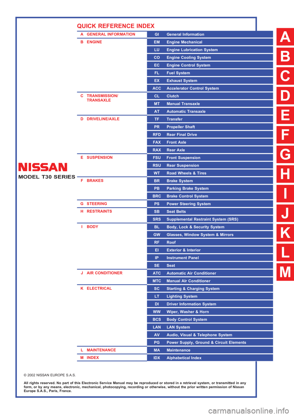
MODEL T30 SERIES
© 2002 NISSAN EUROPE S.A.S.
All rights reserved. No part of this Electronic Service Manual may be reproduced or stored in a retrieval system, or transmitted in any
form, or by any means, electronic, mechanical, photocopying, recording or otherwise, without the prior written permission of Nissan
Europe S.A.S., Paris, France.
A GENERAL INFORMATION
B ENGINE
C TRANSMISSION/
TRANSAXLE
D DRIVELINE/AXLE
E SUSPENSION
F BRAKES
G STEERING
H RESTRAINTS
IBODY
J AIR CONDITIONER
K ELECTRICAL
L MAINTENANCE
M INDEXGI General Information
EM Engine Mechanical
LU Engine Lubrication System
CO Engine Cooling System
EC Engine Control System
FL Fuel System
EX Exhaust System
ACC Accelerator Control System
CL Clutch
MT Manual Transaxle
AT Automatic Transaxle
TF Transfer
PR Propeller Shaft
RFD Rear Final Drive
FAX Front Axle
RAX Rear Axle
FSU Front Suspension
RSU Rear Suspension
WT Road Wheels & Tires
BR Brake System
PB Parking Brake System
BRC Brake Control System
PS Power Steering System
SB Seat Belts
SRS Supplemental Restraint System (SRS)
BL Body, Lock & Security System
GW Glasses, Window System & Mirrors
RF Roof
EI Exterior & Interior
IP Instrument Panel
SE Seat
ATC Automatic Air Conditioner
MTC Manual AIr Conditioner
SC Starting & Charging System
LT Lighting System
DI Driver Information System
WW Wiper, Washer & Horn
BCS Body Control System
LAN LAN System
AV Audio, Visual & Telephone System
PG Power Supply, Ground & Circuit Elements
MA Maintenance
IDX Alphabetical Index
QUICK REFERENCE INDEX
A
B
C
D
E
F
G
H
I
J
K
L
M
Page 755 of 3833

FUEL PUMP CIRCUIT
EC-405
[QR25(WITH EURO-OBD)]
C
D
E
F
G
H
I
J
K
L
MA
EC
FUEL PUMP CIRCUITPFP:17042
DescriptionEBS00MBF
SYSTEM DESCRIPTION
The ECM activates the fuel pump for several seconds after the ignition switch is turned on to improve engine
startability. If the ECM receives a 180° signal from the camshaft position sensor (PHASE), it knows that the
engine is rotating, and causes the pump to operate. If the 180° signal is not received when the ignition switch
is ON, the engine stalls. The ECM stops pump operation and prevents battery discharging, thereby improving
safety. The ECM does not directly drive the fuel pump. It controls the ON/OFF fuel pump relay, which in turn
controls the fuel pump.
COMPONENT DESCRIPTION
A turbine type design fuel pump is used in the fuel tank.
CONSULT-II Reference Value in Data Monitor ModeEBS00MBG
Specification data are reference values.
ECM Terminals and Reference ValueEBS00MBH
Specification data are reference values and are measured between each terminal and ground.
CAUTION:
Do not use ECM ground terminals when measuring input/output voltage. Doing so may result in dam-
age to the ECM's transistor. Use a ground other than ECM terminals, such as the ground.
Sensor Input Signal to ECMECM
FunctionActuator
Crankshaft position sensor (POS) Engine speed
Fuel pump
controlFuel pump relay Camshaft position sensor (PHASE) Engine speed and cylinder number
Ignition switch Start signal
Condition Fuel pump operation
Ignition switch is turned to ON. Operates for 1 second.
Engine running and crankingOperates.
When engine is stoppedStops in 1.5 seconds.
Except as shown aboveStops.
PBIB0513E
MONITOR ITEM CONDITION SPECIFICATION
FUEL PUMP RLY
●For 1 seconds after turning ignition switch ON
●Engine running or crankingON
●Except above conditions OFF
Page 1076 of 3833

EC-726
[QR25(WITHOUT EURO-OBD)]
FUEL PUMP CIRCUIT
FUEL PUMP CIRCUIT
PFP:17042
DescriptionEBS00NKV
SYSTEM DESCRIPTION
The ECM activates the fuel pump for several seconds after the ignition switch is turned on to improve engine
startability. If the ECM receives a 180° signal from the camshaft position sensor (PHASE), it knows that the
engine is rotating, and causes the pump to operate. If the 180° signal is not received when the ignition switch
is ON, the engine stalls. The ECM stops pump operation and prevents battery discharging, thereby improving
safety. The ECM does not directly drive the fuel pump. It controls the ON/OFF fuel pump relay, which in turn
controls the fuel pump.
COMPONENT DESCRIPTION
A turbine type design fuel pump is used in the fuel tank.
CONSULT-II Reference Value in Data Monitor ModeEBS00NKW
Specification data are reference values.
ECM Terminals and Reference ValueEBS00NKX
Specification data are reference values and are measured between each terminal and ground.
CAUTION:
Do not use ECM ground terminals when measuring input/output voltage. Doing so may result in dam-
age to the ECM's transistor. Use a ground other than ECM terminals, such as the ground.
Sensor Input Signal to ECMECM
FunctionActuator
Crankshaft position sensor (POS) Engine speed
Fuel pump
controlFuel pump relay Camshaft position sensor (PHASE) Engine speed and cylinder number
Ignition switch Start signal
Condition Fuel pump operation
Ignition switch is turned to ON. Operates for 1 second.
Engine running and crankingOperates.
When engine is stoppedStops in 1.5 seconds.
Except as shown aboveSto ps.
PBIB0513E
MONITOR ITEM CONDITION SPECIFICATION
FUEL PUMP RLY
●For 1 seconds after turning ignition switch ON
●Engine running or crankingON
●Except above conditions OFF
Page 1442 of 3833

EC-1092
[QR20(WITH EURO-OBD)]
FUEL PUMP CIRCUIT
FUEL PUMP CIRCUIT
PFP:17042
DescriptionEBS00N28
SYSTEM DESCRIPTION
The ECM activates the fuel pump for several seconds after the ignition switch is turned on to improve engine
startability. If the ECM receives a 180° signal from the camshaft position sensor (PHASE), it knows that the
engine is rotating, and causes the pump to operate. If the 180° signal is not received when the ignition switch
is ON, the engine stalls. The ECM stops pump operation and prevents battery discharging, thereby improving
safety. The ECM does not directly drive the fuel pump. It controls the ON/OFF fuel pump relay, which in turn
controls the fuel pump.
COMPONENT DESCRIPTION
A turbine type design fuel pump is used in the fuel tank.
CONSULT-II Reference Value in Data Monitor ModeEBS00N29
Specification data are reference values.
ECM Terminals and Reference ValueEBS00N2A
Specification data are reference values and are measured between each terminal and ground.
CAUTION:
Do not use ECM ground terminals when measuring input/output voltage. Doing so may result in dam-
age to the ECM's transistor. Use a ground other than ECM terminals, such as the ground.
Sensor Input Signal to ECMECM
FunctionActuator
Crankshaft position sensor (POS) Engine speed
Fuel pump
controlFuel pump relay Camshaft position sensor (PHASE) Engine speed and cylinder number
Ignition switch Start signal
Condition Fuel pump operation
Ignition switch is turned to ON. Operates for 1 second.
Engine running and crankingOperates.
When engine is stoppedStops in 1.5 seconds.
Except as shown aboveSto ps.
PBIB0513E
MONITOR ITEM CONDITION SPECIFICATION
FUEL PUMP RLY
●For 1 seconds after turning ignition switch ON
●Engine running or crankingON
●Except above conditions OFF
Page 1716 of 3833

EC-1366
[QR20(WITHOUT EURO-OBD)]
FUEL PUMP CIRCUIT
FUEL PUMP CIRCUIT
PFP:17042
DescriptionEBS00NAF
SYSTEM DESCRIPTION
The ECM activates the fuel pump for several seconds after the ignition switch is turned on to improve engine
startability. If the ECM receives a 180° signal from the camshaft position sensor (PHASE), it knows that the
engine is rotating, and causes the pump to operate. If the 180° signal is not received when the ignition switch
is ON, the engine stalls. The ECM stops pump operation and prevents battery discharging, thereby improving
safety. The ECM does not directly drive the fuel pump. It controls the ON/OFF fuel pump relay, which in turn
controls the fuel pump.
COMPONENT DESCRIPTION
A turbine type design fuel pump is used in the fuel tank.
CONSULT-II Reference Value in Data Monitor ModeEBS00NAG
Specification data are reference values.
ECM Terminals and Reference ValueEBS00NAH
Specification data are reference values and are measured between each terminal and ground.
CAUTION:
Do not use ECM ground terminals when measuring input/output voltage. Doing so may result in dam-
age to the ECM's transistor. Use a ground other than ECM terminals, such as the ground.
Sensor Input Signal to ECMECM
FunctionActuator
Crankshaft position sensor (POS) Engine speed
Fuel pump
controlFuel pump relay Camshaft position sensor (PHASE) Engine speed and cylinder number
Ignition switch Start signal
Condition Fuel pump operation
Ignition switch is turned to ON. Operates for 1 second.
Engine running and crankingOperates.
When engine is stoppedStops in 1.5 seconds.
Except as shown aboveSto ps.
PBIB0513E
MONITOR ITEM CONDITION SPECIFICATION
FUEL PUMP RLY
●For 1 seconds after turning ignition switch ON
●Engine running or crankingON
●Except above conditions OFF
Page 1765 of 3833

TROUBLE DIAGNOSIS
EC-1415
[YD]
C
D
E
F
G
H
I
J
K
L
MA
EC
10.CHECK BATTERY VOLTAGE
Check battery voltage.
OK or NG
OK >> GO TO 12.
NG >> GO TO 11.
11 . CHECK BATTERY
Refer to SC-3, "
BATTERY" .
OK or NG
OK >> Check charging system. Refer to SC-12 .
NG >> Repair or replace.
12.CHECK COMPRESSION PRESSURE
Check compression pressure. Refer to EM-182, "
CHECKING COMPRESSION PRESSURE" .
OK or NG
OK >> GO TO 11.
NG >> Follow the instruction of “CHECKING COMPRESSION PRESSURE”.
13.CHECK IDLE SPEED AGAIN
With CONSULT-II
1. Start engine and let it idle.
2. Select “CKPS·RPM (TDC)” in “DATA MONITOR” mode with CONSULT-II.
3. Read idle speed.
OK or NG
OK >>INSPECTION END
NG >> 1. Replace fuel injector.
2. GO TO 3. Voltage: More than 12.13V
725±25 rpm
SEF817Y
Page 1892 of 3833

EC-1542
[YD]
DTC P1660 BATTERY VOLTAGE
DTC P1660 BATTERY VOLTAGE
PFP:AYBGL
On Board Diagnosis LogicEBS0035A
The ECM checks if battery voltage is within the tolerance range for the engine control system.
DTC Confirmation ProcedureEBS0035B
With CONSULT-II
1. Check the following.
–Jumper cables are connected for jump starting.
–Battery or alternator has been replaced.
If the result is “Yes” for one item or more, skip the following steps and go to EC-1542, "
Diagnostic Proce-
dure" .
2. Check that the positive battery terminal is connected to battery properly. If NG, reconnect it properly.
3. Check that the alternator functions properly. Refer to SC-12, "
CHARGING SYSTEM" .
4. Turn ignition switch “ON” and select “DATA MONITOR” mode with CONSULT-II.
5. Wait one minute.
6. If DTC is detected, go to EC-1542, "
Diagnostic Procedure" .
If DTC is not detected, go to next step.
7. Start engine and wait one minute at idle.
8. If DTC is detected, go to EC-1542, "
Diagnostic Procedure" .
Diagnostic ProcedureEBS0035C
1. INSPECTION START
Are jumper cables connected for the jump starting?
Ye s o r N o
Yes >> GO TO 3.
No >> GO TO 2.
2. CHECK BATTERY AND ALTERNATOR
Check that the proper type of battery and alternator is installed.
Refer to SC-3, "
BATTERY" , SC-12, "CHARGING SYSTEM" .
OK or NG
OK >> GO TO 5.
NG >> Replace with a proper one.
DTC Malfunction is detected when ... Check Items (Possible Cause)
P1660
●An abnormally high or low voltage from the battery
is sent to ECM.●Incorrect jump starting
●Battery
●Alternator
●ECM
Page 2091 of 3833

A/T FLUID
AT-13
D
E
F
G
H
I
J
K
L
MA
B
AT
A/T FLUIDPFP:KLE40
Checking A/T FluidECS004Q7
1. Warm up engine.
2. Check for fluid leakage.
3. Before driving, fluid level can be checked at fluid temperatures
of 30 to 50°C (86 to 122°F) using “COLD” range on dipstick.
a. Park vehicle on level surface and set parking brake.
b. Start engine and move selector lever through each gear posi-
tion. Leave selector lever in “P” position.
c. Check fluid level with engine idling.
d. Remove dipstick and note reading. If level is at low side of either
range, and fluid to the charging pipe.
e. Re-insert dipstick into charging pipe as far as it will go.
f. Remove dipstick and note reading. If reading is at low side of range, add fluid to the charging pipe.
Do not overfill.
4. Drive vehicle for approximately 5 minutes in urban areas.
5. Re-check fluid level at fluid temperatures of 50 to 80°C (122 to 176°F) using “HOT” range on dipstick.
6. Check fluid condition.
●If fluid is very dark or smells burned, refer to AT section for
checking operation of A/T. Flush cooling system after repair of
A/T.
●If A/T fluid contains frictional material (clutches, bands, etc.),
replace radiator and flush cooler line using cleaning solvent
and compressed air after repair of A/T. Refer to CO-11,
"RADIATOR" , CO-14, "RADIATOR (ALUMINUM TYPE)" .
Changing A/T FluidECS004Q8
1. Warm up A/T fluid.
2. Stop engine.
3. Drain A/T fluid from drain plug and refill with new A/T fluid.
Always refill same volume with drained fluid.
4. Run engine at idle speed for five minutes.
5. Check fluid level and condition. Refer to “Checking A/T Fluid”. If fluid is still dirty, repeat steps 2 through 5.
SMA827CA
SMA853B
Fluid grade:
Genuine Nissan ATF or equivalent. Refer to MA-
16, "RECOMMENDED FLUIDS AND LUBRI-
CANTS" .
Fluid capacity (With torque converter):
Approx. 8.5 (7-1/2 lmp qt)
Drain plug:
: 29 - 39 N·m (3.0 - 4.0 kg-m, 22 - 29 ft-lb)
SMA027D
Page 2181 of 3833

TROUBLE DIAGNOSIS — GENERAL DESCRIPTION
AT-103
[EURO-OBD]
D
E
F
G
H
I
J
K
L
MA
B
AT
Transmission overheats. OFF vehicle7. Oil pumpAT-444, "
Oil Pump"
8. Reverse clutchAT-463, "Reverse Clutch"
9. High clutchAT-466, "High Clutch"
10. Brake bandAT-488, "Band Servo Pis-
ton Assembly"
11. Forward clutchAT-471, "Forward and
Overrun Clutches"
12. Overrun clutchAT-471, "Forward and
Overrun Clutches"
13. Low & reverse brakeAT-476, "Low & Reverse
Brake"
14. Torque converterAT-425, "
Locations of
Adjusting Shims, Needle
Bearings, Thrust Washers
and Snap Rings"
ATF shoots out during operation.
White smoke emitted from exhaust
pipe during operation.ON vehicle 1. Fluid levelAT-63, "
FLUID LEVEL
CHECK"
OFF vehicle2. Reverse clutchAT-463, "
Reverse Clutch"
3. High clutchAT-466, "High Clutch"
4. Brake bandAT-488, "Band Servo Pis-
ton Assembly"
5. Forward clutchAT-471, "Forward and
Overrun Clutches"
6. Overrun clutchAT-471, "Forward and
Overrun Clutches"
7. Low & reverse brakeAT-476, "Low & Reverse
Brake"
Offensive smell at fluid charging
pipe.ON vehicle 1. Fluid levelAT-63, "
FLUID LEVEL
CHECK"
OFF vehicle2. Torque converterAT-425, "
Locations of
Adjusting Shims, Needle
Bearings, Thrust Washers
and Snap Rings"
3. Oil pumpAT-444, "Oil Pump"
4. Reverse clutchAT-463, "Reverse Clutch"
5. High clutchAT-466, "High Clutch"
6. Brake bandAT-488, "Band Servo Pis-
ton Assembly"
7. Forward clutchAT-471, "Forward and
Overrun Clutches"
8. Overrun clutchAT-471, "Forward and
Overrun Clutches"
9. Low & reverse brakeAT-476, "Low & Reverse
Brake"
Symptom Condition Diagnostic ItemReference Page
EURO-OBD
Page 2381 of 3833

TROUBLE DIAGNOSIS — GENERAL DESCRIPTION
AT-303
[EXC.F/EURO-OBD]
D
E
F
G
H
I
J
K
L
MA
B
AT
Offensive smell at fluid charging pipe.ON vehicle 1. Fluid levelAT- 2 6 4 , "
FLUID LEVEL
CHECK"
OFF vehicle2. Torque converterAT- 4 2 5 , "
Locations of
Adjusting Shims, Needle
Bearings, Thrust Washers
and Snap Rings"
3. Oil pumpAT- 4 4 4 , "Oil Pump"
4. Reverse clutchAT- 4 6 3 , "Reverse Clutch"
5. High clutchAT- 4 6 6 , "High Clutch"
6. Brake bandAT- 4 8 8 , "Band Servo Pis-
ton Assembly"
7. Forward clutchAT- 4 7 1 , "Forward and
Overrun Clutches"
8. Overrun clutchAT- 4 7 1 , "Forward and
Overrun Clutches"
9. Low & reverse brakeAT- 4 7 6 , "Low & Reverse
Brake"
Torque converter is not locked up. ON vehicle1. Accelerator pedal position (APP) sensorAT- 3 6 2 , "
ACCELE
RATOR PEDAL POSI-
TION (APP) SENSOR"
2. Vehicle speed sensor·A/T (Revolution
sensor) and vehicle speed sensor·MTRAT- 3 5 3 , "
VEHICLE
SPEED SENSOR·A/T
(REVOLUTION SEN-
SOR)",AT-358, "DTC
VEHICLE SPEED SEN-
SOR MTR"
3. Engine speed signalAT- 3 9 2 , "ENGINE SPEED
SIGNAL"
4. A/T fluid temp sen circ and TCM pow
sourAT- 3 8 6 , "
BATT/FLUID
TEMP SEN (A/T FLUID
TEMP SENSOR CIR-
CUIT AND TCM POWER
SOURCE)"
5. Line pressure testAT- 2 6 8 , "Line Pressure
Te s t"
6. Torque converter clutch solenoid valveAT- 3 8 1 , "
TORQUE CON-
VERTER CLUTCH
SOLENOID VALVE"
7. Control valve assemblyAT- 4 1 4 , "
Control Valve
Assembly and Accumula-
tors"
Torque converter is not locked up. OFF vehicle 8. Torque converterAT- 4 2 5 , "
Locations of
Adjusting Shims, Needle
Bearings, Thrust Washers
and Snap Rings"
Symptom Condition Diagnostic Item Reference Page