driver seat adjustment NISSAN X-TRAIL 2001 Service Repair Manual
[x] Cancel search | Manufacturer: NISSAN, Model Year: 2001, Model line: X-TRAIL, Model: NISSAN X-TRAIL 2001Pages: 3833, PDF Size: 39.49 MB
Page 3053 of 3833

BL-1
BODY, LOCK & SECURITY SYSTEM
I BODY
CONTENTS
C
D
E
F
G
H
J
K
L
M
SECTION
A
B
BL
BODY, LOCK & SECURITY SYSTEM
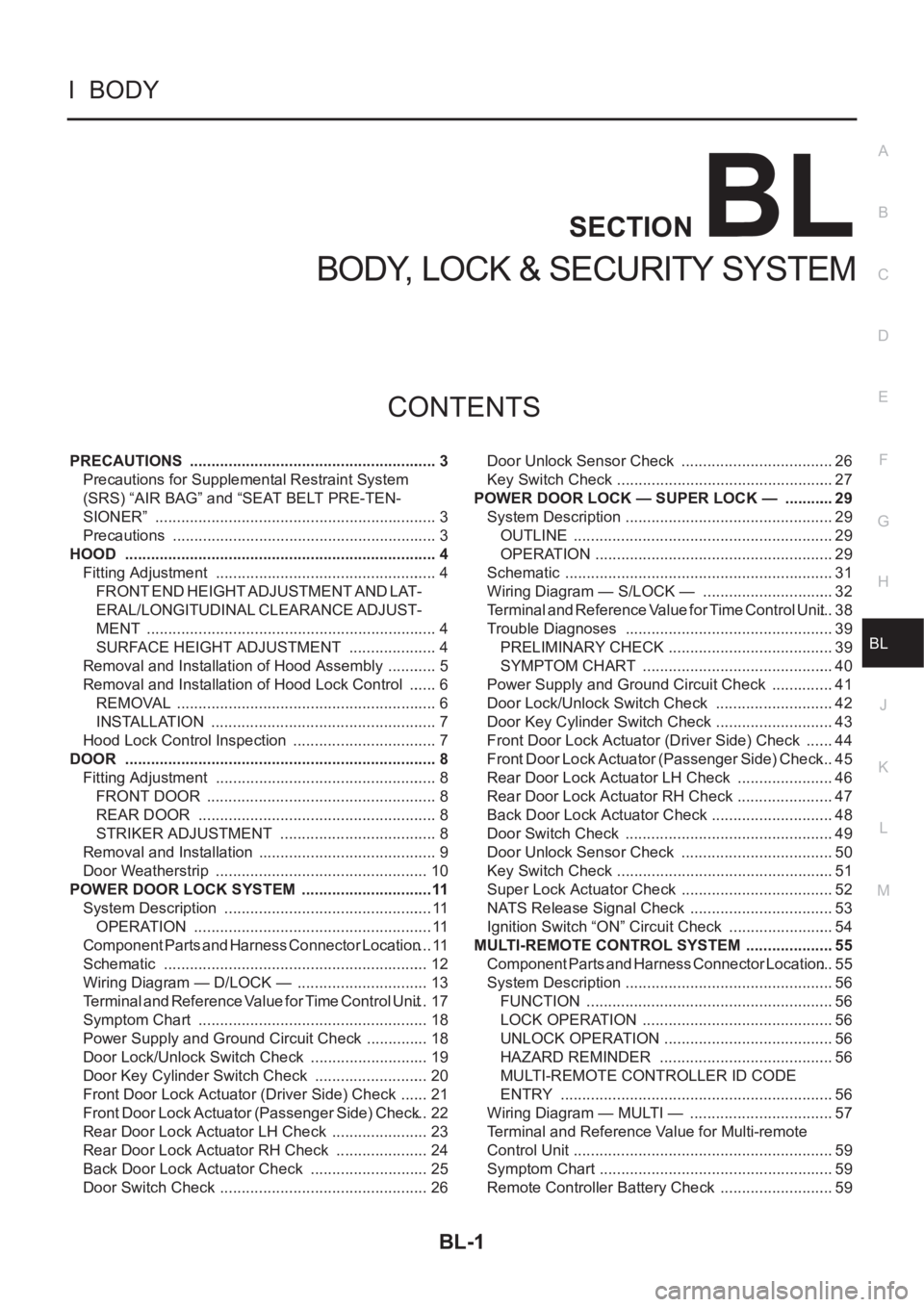
PRECAUTIONS .......................................................... 3
Precautions for Supplemental Restraint System
(SRS) “AIR BAG” and “SEAT BELT PRE-TEN-
SIONER” .................................................................. 3
Precautions .............................................................. 3
HOOD ......................................................................... 4
Fitting Adjustment .................................................... 4
FRONT END HEIGHT ADJUSTMENT AND LAT-
ERAL/LONGITUDINAL CLEARANCE ADJUST-
MENT .................................................................... 4
SURFACE HEIGHT ADJUSTMENT ..................... 4
Removal and Installation of Hood Assembly ............ 5
Removal and Installation of Hood Lock Control ....... 6
REMOVAL ............................................................. 6
INSTALLATION ..................................................... 7
Hood Lock Control Inspection .................................. 7
DOOR ......................................................................... 8
Fitting Adjustment .................................................... 8
FRONT DOOR ...................................................... 8
REAR DOOR ........................................................ 8
STRIKER ADJUSTMENT ..................................... 8
Removal and Installation .......................................... 9
Door Weatherstrip .................................................. 10
POWER DOOR LOCK SYSTEM ...............................11
System Description ................................................. 11
OPERATION ........................................................ 11
Component Parts and Harness Connector Location .... 11
Schematic .............................................................. 12
Wiring Diagram — D/LOCK — ............................... 13
Terminal and Reference Value for Time Control Unit ... 17
Symptom Chart ...................................................... 18
Power Supply and Ground Circuit Check ............... 18
Door Lock/Unlock Switch Check ............................ 19
Door Key Cylinder Switch Check ........................... 20
Front Door Lock Actuator (Driver Side) Check ....... 21
Front Door Lock Actuator (Passenger Side) Check ... 22
Rear Door Lock Actuator LH Check ....................... 23
Rear Door Lock Actuator RH Check ...................... 24
Back Door Lock Actuator Check ............................ 25
Door Switch Check ................................................. 26Door Unlock Sensor Check .................................... 26
Key Switch Check ................................................... 27
POWER DOOR LOCK — SUPER LOCK — ............ 29
System Description ................................................. 29
OUTLINE ............................................................. 29
OPERATION .....................................................
... 29
Schematic ............................................................... 31
Wiring Diagram — S/LOCK — ............................... 32
Terminal and Reference Value for Time Control Unit ... 38
Trouble Diagnoses ................................................. 39
PRELIMINARY CHECK ....................................... 39
SYMPTOM CHART ............................................. 40
Power Supply and Ground Circuit Check ............... 41
Door Lock/Unlock Switch Check ............................ 42
Door Key Cylinder Switch Check ............................ 43
Front Door Lock Actuator (Driver Side) Check ....... 44
Front Door Lock Actuator (Passenger Side) Check ... 45
Rear Door Lock Actuator LH Check ....................... 46
Rear Door Lock Actuator RH Check ....................... 47
Back Door Lock Actuator Check ............................. 48
Door Switch Check ................................................. 49
Door Unlock Sensor Check .................................... 50
Key Switch Check ................................................... 51
Super Lock Actuator Check .................................... 52
NATS Release Signal Check .................................. 53
Ignition Switch “ON” Circuit Check ......................... 54
MULTI-REMOTE CONTROL SYSTEM ..................... 55
Component Parts and Harness Connector Location ... 55
System Description ................................................. 56
FUNCTION .......................................................... 56
LOCK OPERATION ............................................. 56
UNLOCK OPERATION ........................................ 56
HAZARD REMINDER ......................................... 56
MULTI-REMOTE CONTROLLER ID CODE
ENTRY ................................................................ 56
Wiring Diagram — MULTI — .................................. 57
Terminal and Reference Value for Multi-remote
Control Unit ............................................................. 59
Symptom Chart ....................................................... 59
Remote Controller Battery Check ........................... 59
Page 3493 of 3833

PRECAUTION
LT-3
C
D
E
F
G
H
I
J
L
MA
B
LT
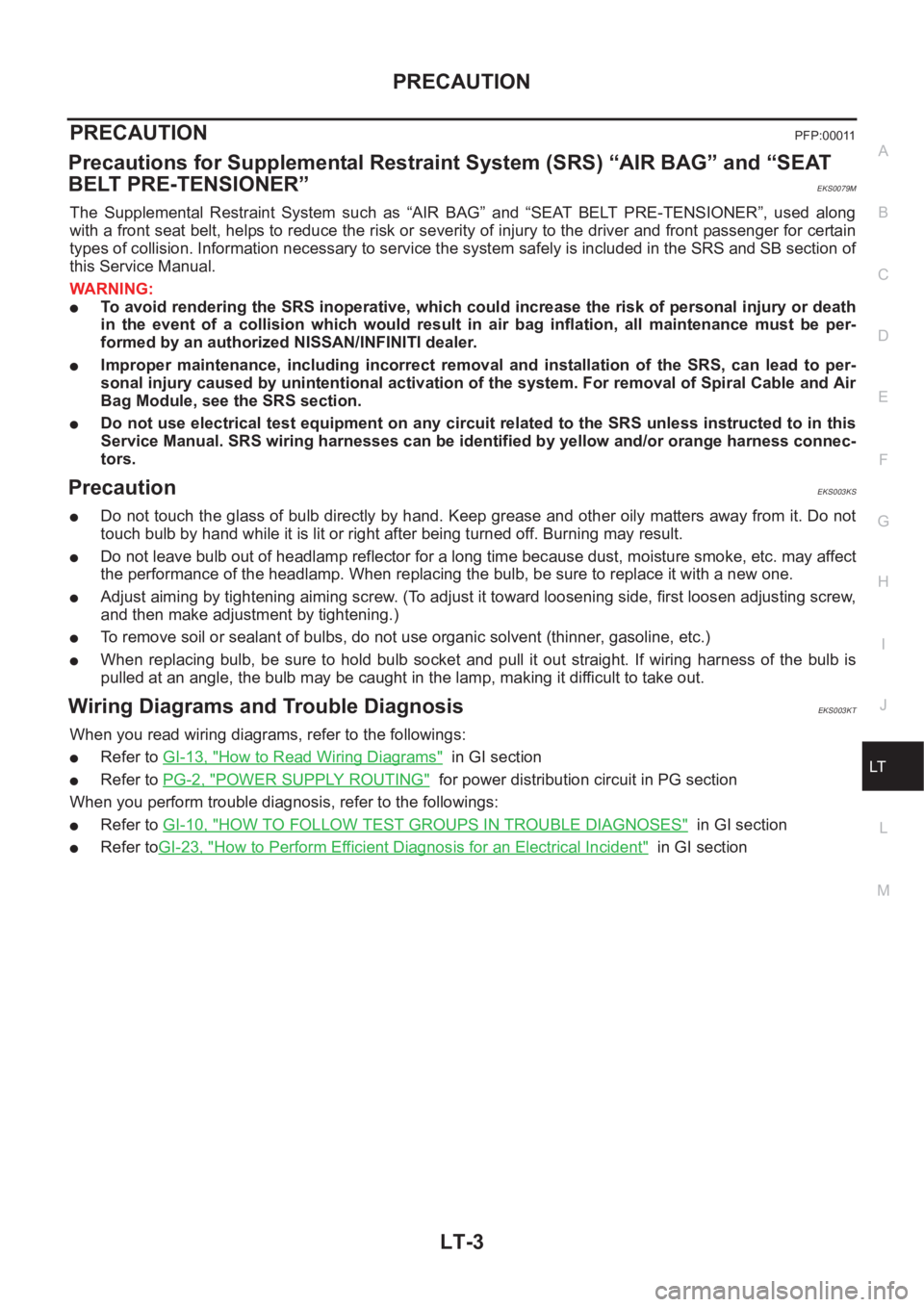
PRECAUTION PFP:00011
Precautions for Supplemental Restraint System (SRS) “AIR BAG” and “SEAT
BELT PRE-TENSIONER”
EKS0079M
The Supplemental Restraint System such as “AIR BAG” and “SEAT BELT PRE-TENSIONER”, used along
with a front seat belt, helps to reduce the risk or severity of injury to the driver and front passenger for certain
types of collision. Information necessary to service the system safely is included in the SRS and SB section of
this Service Manual.
WARNING:
●To avoid rendering the SRS inoperative, which could increase the risk of personal injury or death
in the event of a collision which would result in air bag inflation, all maintenance must be per-
formed by an authorized NISSAN/INFINITI dealer.
●Improper maintenance, including incorrect removal and installation of the SRS, can lead to per-
sonal injury caused by unintentional activation of the system. For removal of Spiral Cable and Air
Bag Module, see the SRS section.
●Do not use electrical test equipment on any circuit related to the SRS unless instructed to in this
Service Manual. SRS wiring harnesses can be identified by yellow and/or orange harness connec-
tors.
Precaution EKS003KS
●Do not touch the glass of bulb directly by hand. Keep grease and other oily matters away from it. Do not
touch bulb by hand while it is lit or right after being turned off. Burning may result.
●Do not leave bulb out of headlamp reflector for a long time because dust, moisture smoke, etc. may affect
the performance of the headlamp. When replacing the bulb, be sure to replace it with a new one.
●Adjust aiming by tightening aiming screw. (To adjust it toward loosening side, first loosen adjusting screw,
and then make adjustment by tightening.)
●To remove soil or sealant of bulbs, do not use organic solvent (thinner, gasoline, etc.)
●When replacing bulb, be sure to hold bulb socket and pull it out straight. If wiring harness of the bulb is
pulled at an angle, the bulb may be caught in the lamp, making it difficult to take out.
Wiring Diagrams and Trouble Diagnosis EKS003KT
When you read wiring diagrams, refer to the followings:
●Refer to GI-13, "How to Read Wiring Diagrams" in GI section
●Refer to PG-2, "POWER SUPPLY ROUTING" for power distribution circuit in PG section
When you perform trouble diagnosis, refer to the followings:
●Refer to GI-10, "HOW TO FOLLOW TEST GROUPS IN TROUBLE DIAGNOSES" in GI section
●Refer toGI-23, "How to Perform Efficient Diagnosis for an Electrical Incident" in GI section