warning NISSAN X-TRAIL 2001 Service Repair Manual
[x] Cancel search | Manufacturer: NISSAN, Model Year: 2001, Model line: X-TRAIL, Model: NISSAN X-TRAIL 2001Pages: 3833, PDF Size: 39.49 MB
Page 7 of 3833
PRECAUTIONS
GI-5
C
D
E
F
G
H
I
J
K
L
MB
GI
●Use approved bonding agent, sealants or their equivalents when required.
●Use tools and recommended special tools where specified for safe and efficient service repairs.
●When repairing the fuel, oil, water, vacuum or exhaust systems, check all affected lines for leaks.
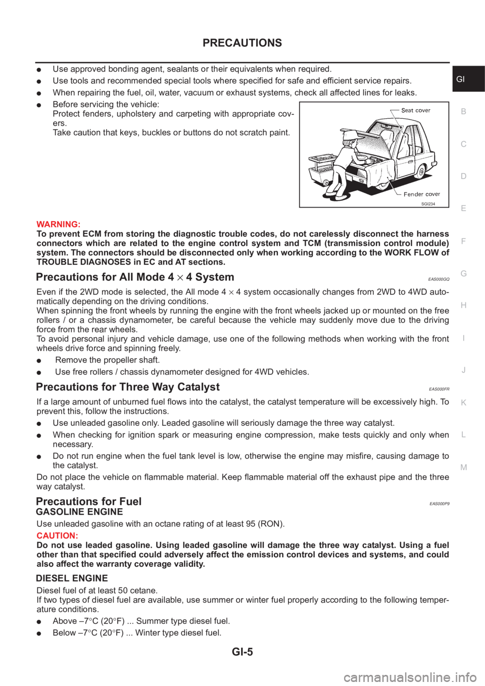
●Before servicing the vehicle:
Protect fenders, upholstery and carpeting with appropriate cov-
ers.
Take caution that keys, buckles or buttons do not scratch paint.
WARNING:
To prevent ECM from storing the diagnostic trouble codes, do not carelessly disconnect the harness
connectors which are related to the engine control system and TCM (transmission control module)
system. The connectors should be disconnected only when working according to the WORK FLOW of
TROUBLE DIAGNOSES in EC and AT sections.
Precautions for All Mode 4 × 4 SystemEAS000GQ
Even if the 2WD mode is selected, the All mode 4 × 4 system occasionally changes from 2WD to 4WD auto-
matically depending on the driving conditions.
When spinning the front wheels by running the engine with the front wheels jacked up or mounted on the free
rollers / or a chassis dynamometer, be careful because the vehicle may suddenly move due to the driving
force from the rear wheels.
To avoid personal injury and vehicle damage, use one of the following methods when working with the front
wheels drive force and spinning freely.
● Remove the propeller shaft.
● Use free rollers / chassis dynamometer designed for 4WD vehicles.
Precautions for Three Way CatalystEAS000FR
If a large amount of unburned fuel flows into the catalyst, the catalyst temperature will be excessively high. To
prevent this, follow the instructions.
●Use unleaded gasoline only. Leaded gasoline will seriously damage the three way catalyst.
●When checking for ignition spark or measuring engine compression, make tests quickly and only when
necessary.
●Do not run engine when the fuel tank level is low, otherwise the engine may misfire, causing damage to
the catalyst.
Do not place the vehicle on flammable material. Keep flammable material off the exhaust pipe and the three
way catalyst.
Precautions for FuelEAS000P9
GASOLINE ENGINE
Use unleaded gasoline with an octane rating of at least 95 (RON).
CAUTION:
Do not use leaded gasoline. Using leaded gasoline will damage the three way catalyst. Using a fuel
other than that specified could adversely affect the emission control devices and systems, and could
also affect the warranty coverage validity.
DIESEL ENGINE
Diesel fuel of at least 50 cetane.
If two types of diesel fuel are available, use summer or winter fuel properly according to the following temper-
ature conditions.
●Above –7°C (20°F) ... Summer type diesel fuel.
●Below –7°C (20°F) ... Winter type diesel fuel.
SGI234
Page 10 of 3833
GI-8
HOW TO USE THIS MANUAL
HOW TO USE THIS MANUAL
PFP:00008
Description EAS000FY
This volume explains “Removal, Disassembly, Installation, Inspection and Adjustment” and “Trouble Diag-
noses”.
Te r m sEAS000FZ
●The captions WARNING and CAUTION warn you of steps that must be followed to prevent personal
injury and/or damage to some part of the vehicle.
WARNING indicates the possibility of personal injury if instructions are not followed.
CAUTION indicates the possibility of component damage if instructions are not followed.
BOLD TYPED STATEMENTS except WARNING and CAUTION give you helpful information.
Standard value:Tolerance at inspection and adjustment.
Limit value:The maximum or minimum limit value that should not be exceeded at inspection and adjust-
ment.
UnitsEAS000G0
●The UNITS given in this manual are primarily expressed as the SI UNIT (International System of Unit),
and alternatively expressed in the metric system and in the yard/pound system.
“Example”
ContentsEAS000G1
●ALPHABETICAL INDEX is provided at the end of this manual so that you can rapidly find the item and
page you are searching for.
●A QUICK REFERENCE INDEX, a black tab (e.g. ) is provided on the first page. You can quickly find
the first page of each section by matching it to the section's black tab.
●THE CONTENTS are listed on the first page of each section.
●THE TITLE is indicated on the upper portion of each page and shows the part or system.
●THE PAGE NUMBER of each section consists of two or three letters which designate the particular sec-
tion and a number (e.g. “BR-5”).
●THE SMALL ILLUSTRATIONS show the important steps such as inspection, use of special tools, knacks
of work and hidden or tricky steps which are not shown in the previous large illustrations.
Assembly, inspection and adjustment procedures for the complicated units such as the automatic tran-
saxle or transmission, etc. are presented in a step-by-step format where necessary.
ComponentsEAS000G2
●THE LARGE ILLUSTRATIONS are exploded views (See the following) and contain tightening torques,
lubrication points, section number of the PARTS CATALOG (e.g. SEC. 440) and other information neces-
sary to perform repairs.Outer Socket Lock Nut : 59 - 78 N-m (6.0 - 8.0 kg-m, 43 - 58 ft-lb)
Page 35 of 3833
CONSULT-II CHECKING SYSTEM
GI-33
C
D
E
F
G
H
I
J
K
L
MB
GI
CONSULT-II CHECKING SYSTEMPFP:00000
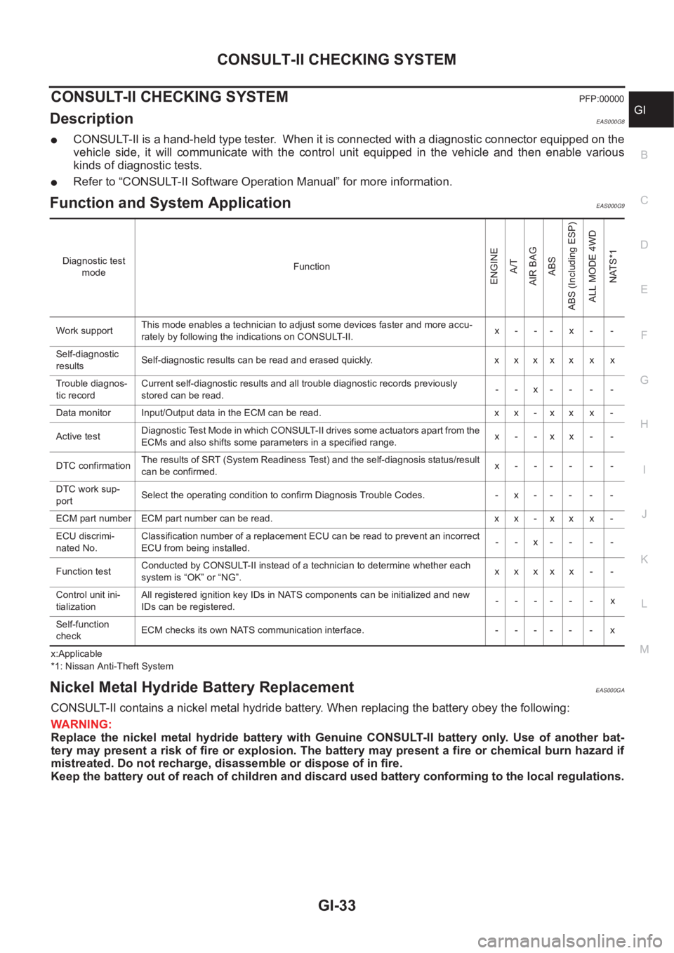
DescriptionEAS000G8
●CONSULT-II is a hand-held type tester. When it is connected with a diagnostic connector equipped on the
vehicle side, it will communicate with the control unit equipped in the vehicle and then enable various
kinds of diagnostic tests.
●Refer to “CONSULT-II Software Operation Manual” for more information.
Function and System Application EAS000G9
x:Applicable
*1: Nissan Anti-Theft System
Nickel Metal Hydride Battery Replacement EAS000GA
CONSULT-II contains a nickel metal hydride battery. When replacing the battery obey the following:
WARNING:
Replace the nickel metal hydride battery with Genuine CONSULT-II battery only. Use of another bat-
tery may present a risk of fire or explosion. The battery may present a fire or chemical burn hazard if
mistreated. Do not recharge, disassemble or dispose of in fire.
Keep the battery out of reach of children and discard used battery conforming to the local regulations.
Diagnostic test
modeFunction
ENGINE
A/T
AIR BAG
ABS
ABS (Including ESP)
ALL MODE 4WD
NATS*1
Work supportThis mode enables a technician to adjust some devices faster and more accu-
rately by following the indications on CONSULT-II.x- -- x- -
Self-diagnostic
resultsSelf-diagnostic results can be read and erased quickly. x x x x x x x
Trouble diagnos-
tic recordCurrent self-diagnostic results and all trouble diagnostic records previously
stored can be read.--x----
Data monitor Input/Output data in the ECM can be read. x x - x x x -
Active testDiagnostic Test Mode in which CONSULT-II drives some actuators apart from the
ECMs and also shifts some parameters in a specified range.x- -xx- -
DTC confirmationThe results of SRT (System Readiness Test) and the self-diagnosis status/result
can be confirmed.x------
DTC work sup-
portSelect the operating condition to confirm Diagnosis Trouble Codes. -x-----
ECM part number ECM part number can be read. x x - x x x -
ECU discrimi-
nated No.Classification number of a replacement ECU can be read to prevent an incorrect
ECU from being installed.--x----
Function testConducted by CONSULT-II instead of a technician to determine whether each
system is “OK” or “NG”.xxxxx - -
Control unit ini-
tializationAll registered ignition key IDs in NATS components can be initialized and new
IDs can be registered.------x
Self-function
checkECM checks its own NATS communication interface. - - - - - - x
Page 37 of 3833
LIFTING POINT
GI-35
C
D
E
F
G
H
I
J
K
L
MB
GI
LIFTING POINTPFP:00000
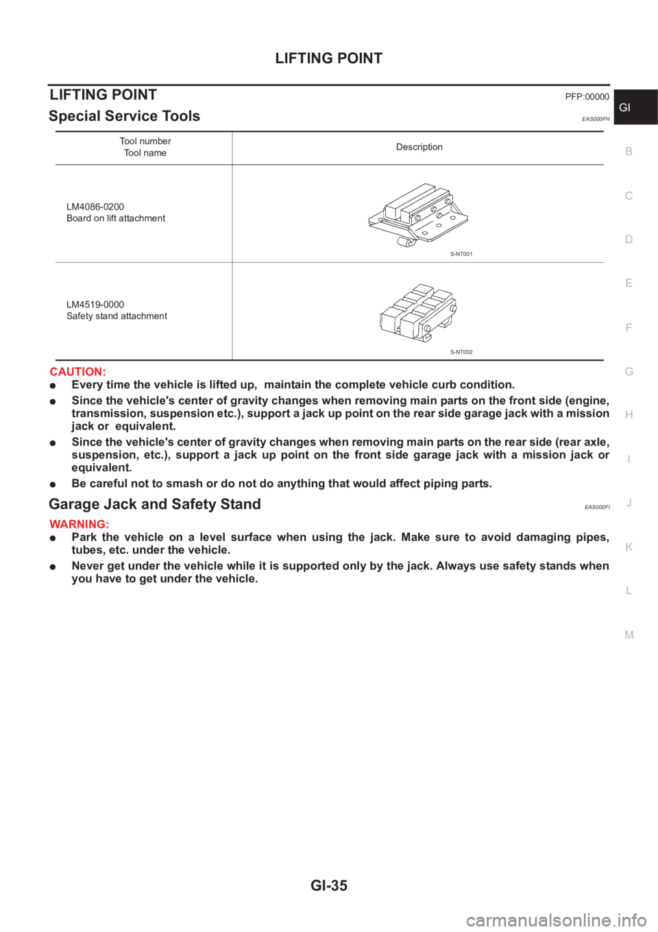
Special Service Tools EAS000FH
CAUTION:
●Every time the vehicle is lifted up, maintain the complete vehicle curb condition.
●Since the vehicle's center of gravity changes when removing main parts on the front side (engine,
transmission, suspension etc.), support a jack up point on the rear side garage jack with a mission
jack or equivalent.
●Since the vehicle's center of gravity changes when removing main parts on the rear side (rear axle,
suspension, etc.), support a jack up point on the front side garage jack with a mission jack or
equivalent.
●Be careful not to smash or do not do anything that would affect piping parts.
Garage Jack and Safety Stand EAS000FI
WARNING:
●Park the vehicle on a level surface when using the jack. Make sure to avoid damaging pipes,
tubes, etc. under the vehicle.
●Never get under the vehicle while it is supported only by the jack. Always use safety stands when
you have to get under the vehicle.
Tool number
Tool nameDescription
LM4086-0200
Board on lift attachment
LM4519-0000
Safety stand attachment
S-NT001
S-NT002
Page 38 of 3833
GI-36
LIFTING POINT
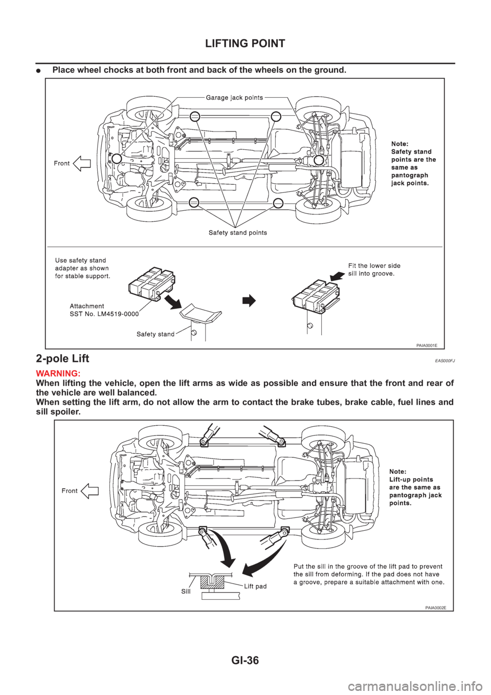
●Place wheel chocks at both front and back of the wheels on the ground.
2-pole Lift EAS000FJ
WARNING:
When lifting the vehicle, open the lift arms as wide as possible and ensure that the front and rear of
the vehicle are well balanced.
When setting the lift arm, do not allow the arm to contact the brake tubes, brake cable, fuel lines and
sill spoiler.
PAIA0001E
PAIA0002E
Page 41 of 3833
TOW TRUCK TOWING
GI-39
C
D
E
F
G
H
I
J
K
L
MB
GI
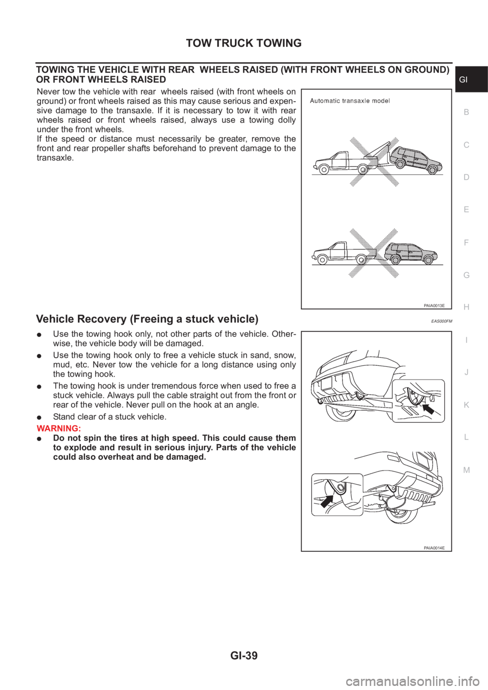
TOWING THE VEHICLE WITH REAR WHEELS RAISED (WITH FRONT WHEELS ON GROUND)
OR FRONT WHEELS RAISED
Never tow the vehicle with rear wheels raised (with front wheels on
ground) or front wheels raised as this may cause serious and expen-
sive damage to the transaxle. If it is necessary to tow it with rear
wheels raised or front wheels raised, always use a towing dolly
under the front wheels.
If the speed or distance must necessarily be greater, remove the
front and rear propeller shafts beforehand to prevent damage to the
transaxle.
Vehicle Recovery (Freeing a stuck vehicle) EAS000FM
●Use the towing hook only, not other parts of the vehicle. Other-
wise, the vehicle body will be damaged.
●Use the towing hook only to free a vehicle stuck in sand, snow,
mud, etc. Never tow the vehicle for a long distance using only
the towing hook.
●The towing hook is under tremendous force when used to free a
stuck vehicle. Always pull the cable straight out from the front or
rear of the vehicle. Never pull on the hook at an angle.
●Stand clear of a stuck vehicle.
WARNING:
●Do not spin the tires at high speed. This could cause them
to explode and result in serious injury. Parts of the vehicle
could also overheat and be damaged.
PAIA0013E
PAIA0014E
Page 62 of 3833
![NISSAN X-TRAIL 2001 Service Repair Manual EM-12
[QR]
DRIVE BELTS
DRIVE BELTS
PFP:02117
Checking Drive BeltsEBS00KN7
WARNING:
Be sure to perform when the engine is stopped.
●Make sure that the indicator (single line notch on fixed side) of d NISSAN X-TRAIL 2001 Service Repair Manual EM-12
[QR]
DRIVE BELTS
DRIVE BELTS
PFP:02117
Checking Drive BeltsEBS00KN7
WARNING:
Be sure to perform when the engine is stopped.
●Make sure that the indicator (single line notch on fixed side) of d](/img/5/57405/w960_57405-61.png)
EM-12
[QR]
DRIVE BELTS
DRIVE BELTS
PFP:02117
Checking Drive BeltsEBS00KN7
WARNING:
Be sure to perform when the engine is stopped.
●Make sure that the indicator (single line notch on fixed side) of drive belt auto-tensioner is within the pos-
sible use range (between three line notches on moving side).
NOTE:
●Check the drive belt auto-tensioner indicator (single line notch on fixed side) when the engine is cold.
●When the new drive belt is installed, the indicator (single line notch on fixed side) should be within the
range A.
●Visually check entire belt for wear, damage or cracks.
●If the indicator (single line notch on fixed side) is out of possible use range or belt is damaged, replace the
belt.
Tension AdjustmentEBS00KN8
Belt tensioning is not necessary, as it is automatically adjusted by drive belt auto-tensioner.
Removal and InstallationEBS00KN9
REMOVAL
1. Remove splash cover on RH undercover.
2. With box wrench, and while securely holding the hexagonal part
in pulley center of drive belt auto-tensioner, move the wrench
handle in the direction of arrow (loosening direction of ten-
sioner).
CAUTION:
Avoid placing hand in a location where pinching may occur
if the holding tool accidentally comes off.
3. Insert a rod approximately 6 mm (0.24 in) in diameter into retain-
ing boss to fix auto-tensioner pulley.
●Leave auto-tensioner pulley arm locked until belt is installed
again.
4. Loosen drive belt from water pump pulley in sequence, and remove it.
PBIC1234E
KBIA0088E
Page 67 of 3833
![NISSAN X-TRAIL 2001 Service Repair Manual INTAKE MANIFOLD
EM-17
[QR]
C
D
E
F
G
H
I
J
K
L
MA
EM
QR25DE
REMOVAL
WARNING:
To avoid the danger of being scalded, never drain the coolant when the engine is hot.
1. Disconnect mass air flow sensor ha NISSAN X-TRAIL 2001 Service Repair Manual INTAKE MANIFOLD
EM-17
[QR]
C
D
E
F
G
H
I
J
K
L
MA
EM
QR25DE
REMOVAL
WARNING:
To avoid the danger of being scalded, never drain the coolant when the engine is hot.
1. Disconnect mass air flow sensor ha](/img/5/57405/w960_57405-66.png)
INTAKE MANIFOLD
EM-17
[QR]
C
D
E
F
G
H
I
J
K
L
MA
EM
QR25DE
REMOVAL
WARNING:
To avoid the danger of being scalded, never drain the coolant when the engine is hot.
1. Disconnect mass air flow sensor harness connector from mass air flow sensor and clamp.
2. Release fuel pressure. Refer to EC-775, "
FUEL PRESSURE RELEASE" [QR20DE (WITH EURO-OBD)],
EC-1139, "
FUEL PRESSURE RELEASE" [QR20DE (WITHOUT EURO-OBD)], EC-42, "FUEL PRES-
SURE RELEASE" [QR25DE (WITH EURO-OBD)] or EC-452, "FUEL PRESSURE RELEASE" [QR25DE
(WITHOUT EURO-OBD)].
3. Remove air cleaner case and air duct assembly. Refer to EM-14, "
AIR CLEANER AND AIR DUCT" .
4. Drain coolant when engine is cooled. Refer to CO-9, "
DRAINING ENGINE COOLANT" .
SBIA0229E
1. Bracket 2. PCV hose 3. Intake manifold collector
4. Gasket 5. Electric throttle control actuator 6. Intake manifold support
7.EVAP canister purge volume control
solenoid valve8. Vacuum hose 9. Intake manifold
10. Vacuum reservoir tank 11. VIAS control solenoid valve
Page 76 of 3833
![NISSAN X-TRAIL 2001 Service Repair Manual EM-26
[QR]
OIL PAN AND OIL STRAINER
OIL PAN AND OIL STRAINER
P F P : 1111 0
Removal and InstallationEBS00KNE
REMOVAL
WARNING:
To avoid the danger of being scalded, never drain the engine oil when the NISSAN X-TRAIL 2001 Service Repair Manual EM-26
[QR]
OIL PAN AND OIL STRAINER
OIL PAN AND OIL STRAINER
P F P : 1111 0
Removal and InstallationEBS00KNE
REMOVAL
WARNING:
To avoid the danger of being scalded, never drain the engine oil when the](/img/5/57405/w960_57405-75.png)
EM-26
[QR]
OIL PAN AND OIL STRAINER
OIL PAN AND OIL STRAINER
P F P : 1111 0
Removal and InstallationEBS00KNE
REMOVAL
WARNING:
To avoid the danger of being scalded, never drain the engine oil when the engine is hot.
1. Remove engine undercover both side.
2. Drain engine oil. Refer to LU-8, "
Changing Engine Oil" .
3. Remove lower oil pan bolts, Loosen bolts in the reverse order of
that shown in the figure.
KBIA0095E
1. Oil level gauge guide 2. Oil pan upper 3. Cylinder block
4. Oil filter 5. Oil strainer 6. Drain plug
7. Oil pan lower 8. Rear plate cover
KBIA0096E
Page 119 of 3833
![NISSAN X-TRAIL 2001 Service Repair Manual ENGINE ASSEMBLY
EM-69
[QR]
C
D
E
F
G
H
I
J
K
L
MA
EM
ENGINE ASSEMBLYPFP:10001
Removal and InstallationEBS00KNT
WARNING:
●Situate vehicle on a flat and solid surface.
●Place chocks at front and bac NISSAN X-TRAIL 2001 Service Repair Manual ENGINE ASSEMBLY
EM-69
[QR]
C
D
E
F
G
H
I
J
K
L
MA
EM
ENGINE ASSEMBLYPFP:10001
Removal and InstallationEBS00KNT
WARNING:
●Situate vehicle on a flat and solid surface.
●Place chocks at front and bac](/img/5/57405/w960_57405-118.png)
ENGINE ASSEMBLY
EM-69
[QR]
C
D
E
F
G
H
I
J
K
L
MA
EM
ENGINE ASSEMBLYPFP:10001
Removal and InstallationEBS00KNT
WARNING:
●Situate vehicle on a flat and solid surface.
●Place chocks at front and back of rear wheels.
●For engines not equipped with engine slingers, attach proper slingers and bolts described in
PARTS CATALOG.
CAUTION:
●Always be careful to work safely, avoid forceful or uninstructed operations.
●Do not start working until exhaust system and engine coolant are cool enough.
●If items or work required are not covered by the engine main body section, refer to the applicable
sections.
●Always use the support point specified for lifting.
●Use either 2-pole lift type or separate type lift as best you can. If board-on type is used for
unavoidable reasons, support at the rear axle jacking point with transmission jack or similar tool
before starting work, in preparation for the backward shift of center of gravity.
●For supporting points for lifting and jacking point at rear axle, refer to GI-35, "Garage Jack and
Safety Stand" .
REMOVAL
Description of work
Remove engine, transaxle and transfer assembly with front suspension member from vehicle down ward.
Separate suspension member, and then separate engine and transaxle.
Preparation
PBIC1262E
1. Rear engine mounting insulator 2. Rear engine mounting bracket 3. RH engine mounting insulator
4. RH engine mounting bracket 5. Front engine mounting bracket 6. Front engine mounting insulator
7. Center member 8. LH engine mounting insulator 9. LH engine mounting bracket
10. Stopper 11. Grommet (2pcs)