battery replacement NISSAN X-TRAIL 2001 Service Repair Manual
[x] Cancel search | Manufacturer: NISSAN, Model Year: 2001, Model line: X-TRAIL, Model: NISSAN X-TRAIL 2001Pages: 3833, PDF Size: 39.49 MB
Page 3 of 3833
GI-1
GENERAL INFORMATION
A GENERAL INFORMATION
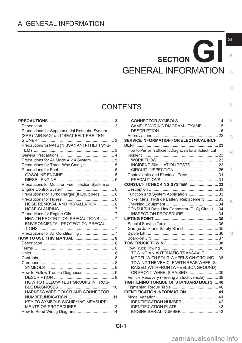
CONTENTS
C
D
E
F
G
H
I
J
K
L
MB
GI
SECTION
GENERAL INFORMATION
PRECAUTIONS .......................................................... 3
Description ............................................................... 3
Precautions for Supplemental Restraint System
(SRS) “AIR BAG” and “SEAT BELT PRE-TEN-
SIONER” .................................................................. 3
Precautions for NATS (NISSAN ANTI-THEFT SYS-
TEM) ........................................................................ 3
General Precautions ................................................ 4
Precautions for All Mode 4 × 4 System .................... 5
Precautions for Three Way Catalyst ......................... 5
Precautions for Fuel ................................................. 5
GASOLINE ENGINE ............................................. 5
DIESEL ENGINE ................................................... 5
Precautions for Multiport Fuel Injection System or
Engine Control System ............................................ 6
Precautions for Turbocharger (If Equipped) ............. 6
Precautions for Hoses .............................................. 6
HOSE REMOVAL AND INSTALLATION ............... 6
HOSE CLAMPING ................................................ 7
Precautions for Engine Oils ...................................... 7
HEALTH PROTECTION PRECAUTIONS ............. 7
ENVIRONMENTAL PROTECTION PRECAU-
TIONS ................................................................... 7
Precautions for Air Conditioning ............................... 7
HOW TO USE THIS MANUAL ................................... 8
Description ............................................................... 8
Terms ....................................................................... 8
Units ......................................................................... 8
Contents ................................................................... 8
Components ............................................................. 8
SYMBOLS ............................................................. 9
How to Follow Trouble Diagnoses ............................ 9
DESCRIPTION ...................................................... 9
HOW TO FOLLOW TEST GROUPS IN TROU-
BLE DIAGNOSES ............................................... 10
HARNESS WIRE COLOR AND CONNECTOR
NUMBER INDICATION ........................................ 11
KEY TO SYMBOLS SIGNIFYING MEASURE-
MENTS OR PROCEDURES ............................... 12
How to Read Wiring Diagrams ............................... 14CONNECTOR SYMBOLS ................................... 14
SAMPLE/WIRING DIAGRAM - EXAMPL - .......... 15
DESCRIPTION .................................................... 16
Abbreviations .......................................................... 22
SERVICE INFORMATION FOR ELECTRICAL INCI-
DENT ......................................................................... 23
How to Perform Efficient Diagnosis for an Electrical
Incident ................................................................... 23
WORK FLOW ...................................................... 23
INCIDENT SIMULATION TESTS ........................ 23
CIRCUIT INSPECTION ....................................... 26
Control Units and Electrical Parts ........................
... 31
PRECAUTIONS .................................................. 31
CONSULT-II CHECKING SYSTEM .......................... 33
Description .............................................................. 33
Function and System Application ........................... 33
Nickel Metal Hydride Battery Replacement ............ 33
Checking Equipment .............................................. 34
CONSULT-II Data Link Connector (DLC) Circuit .... 34
INSPECTION PROCEDURE .............................. 34
LIFTING POINT ......................................................... 35
Special Service Tools ............................................. 35
Garage Jack and Safety Stand ............................... 35
2-pole Lift ................................................................ 36
Board-on Lift ........................................................... 37
TOW TRUCK TOWING ............................................. 38
Tow Truck Towing ................................................... 38
TOWING AN AUTOMATIC TRANSAXLE
MODEL WITH FOUR WHEELS ON GROUND ... 38
T O W I N G T H E V E H I C L E W I T H R E A R W H E E L S
R A I S E D ( W I T H F R O N T W H E E L S O N G R O U N D )
OR FRONT WHEELS RAISED ........................... 39
Vehicle Recovery (Freeing a stuck vehicle) ............ 39
TIGHTENING TORQUE OF STANDARD BOLTS .... 40
Tightening Torque Table ......................................... 40
IDENTIFICATION INFORMATION ............................ 41
Model Variation ....................................................... 41
IDENTIFICATION NUMBER ................................ 42
IDENTIFICATION PLATE .................................... 43
ENGINE SERIAL NUMBER ................................ 43
Page 35 of 3833
CONSULT-II CHECKING SYSTEM
GI-33
C
D
E
F
G
H
I
J
K
L
MB
GI
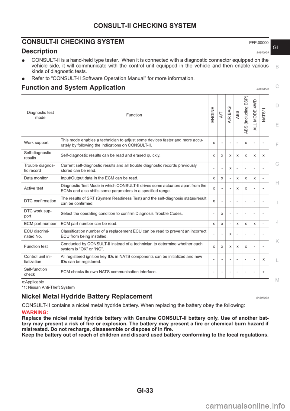
CONSULT-II CHECKING SYSTEMPFP:00000
DescriptionEAS000G8
●CONSULT-II is a hand-held type tester. When it is connected with a diagnostic connector equipped on the
vehicle side, it will communicate with the control unit equipped in the vehicle and then enable various
kinds of diagnostic tests.
●Refer to “CONSULT-II Software Operation Manual” for more information.
Function and System Application EAS000G9
x:Applicable
*1: Nissan Anti-Theft System
Nickel Metal Hydride Battery Replacement EAS000GA
CONSULT-II contains a nickel metal hydride battery. When replacing the battery obey the following:
WARNING:
Replace the nickel metal hydride battery with Genuine CONSULT-II battery only. Use of another bat-
tery may present a risk of fire or explosion. The battery may present a fire or chemical burn hazard if
mistreated. Do not recharge, disassemble or dispose of in fire.
Keep the battery out of reach of children and discard used battery conforming to the local regulations.
Diagnostic test
modeFunction
ENGINE
A/T
AIR BAG
ABS
ABS (Including ESP)
ALL MODE 4WD
NATS*1
Work supportThis mode enables a technician to adjust some devices faster and more accu-
rately by following the indications on CONSULT-II.x- -- x- -
Self-diagnostic
resultsSelf-diagnostic results can be read and erased quickly. x x x x x x x
Trouble diagnos-
tic recordCurrent self-diagnostic results and all trouble diagnostic records previously
stored can be read.--x----
Data monitor Input/Output data in the ECM can be read. x x - x x x -
Active testDiagnostic Test Mode in which CONSULT-II drives some actuators apart from the
ECMs and also shifts some parameters in a specified range.x- -xx- -
DTC confirmationThe results of SRT (System Readiness Test) and the self-diagnosis status/result
can be confirmed.x------
DTC work sup-
portSelect the operating condition to confirm Diagnosis Trouble Codes. -x-----
ECM part number ECM part number can be read. x x - x x x -
ECU discrimi-
nated No.Classification number of a replacement ECU can be read to prevent an incorrect
ECU from being installed.--x----
Function testConducted by CONSULT-II instead of a technician to determine whether each
system is “OK” or “NG”.xxxxx - -
Control unit ini-
tializationAll registered ignition key IDs in NATS components can be initialized and new
IDs can be registered.------x
Self-function
checkECM checks its own NATS communication interface. - - - - - - x
Page 2788 of 3833
![NISSAN X-TRAIL 2001 Service Repair Manual BRC-4
[4WD/ABS]
PRECAUTIONS
[4WD/ABS]PRECAUTIONSPFP:00001
Precautions for brake systemEFS001B6
●Recommended fluid is brake fluid “DOT 3 ”or “DOT 4”.
●Never reuse drained brake fluid.
●Be NISSAN X-TRAIL 2001 Service Repair Manual BRC-4
[4WD/ABS]
PRECAUTIONS
[4WD/ABS]PRECAUTIONSPFP:00001
Precautions for brake systemEFS001B6
●Recommended fluid is brake fluid “DOT 3 ”or “DOT 4”.
●Never reuse drained brake fluid.
●Be](/img/5/57405/w960_57405-2787.png)
BRC-4
[4WD/ABS]
PRECAUTIONS
[4WD/ABS]PRECAUTIONSPFP:00001
Precautions for brake systemEFS001B6
●Recommended fluid is brake fluid “DOT 3 ”or “DOT 4”.
●Never reuse drained brake fluid.
●Be careful not to splash brake fluid on painted areas.
●To clean or wash all parts of master cylinder, disc brake caliper and wheel cylinder, use clean brake fluid.
●Never use mineral oils such as gasoline or kerosene. They will ruin rubber parts of the hydraulic system.
●Use flare nut wrench when removing and installing brake tube.
●Always torque brake lines when installing.
●Burnish the brake contact surfaces after refinishing or replacing
drums or rotors, after replacing pads or linings, or if a soft pedal
occurs at very low mileage. Refer to BR-10, "
Brake Burnishing
Procedure" .
●Before working, turn OFF ignition switch. Disconnect connectors
for ABS actuator and control module or battery terminals.
WARNING:
●Clean brake pads and shoes with a waste cloth, then wipe
with a dust collector.
Precautions for brake controlEFS001B7
●If malfunction is indicated by 4WD warning lamp and/or ABS warning lamp, collect necessary information
from customer (what symptoms are present under what conditions). Find out possible causes before start-
ing service. Besides electrical system inspection, check operation of ABS actuator.
●If malfunction is detected, proceed to trouble diagnosis after checking tire pressure and tire wear.
●Stopping distance or steering stability may be deteriorated by the following conditions. Tire size and type
are in improper combination. Brake pads are not Nissan genuine parts.
●Fitting tires of different size on vehicle can be cause of longitudinal vibration. Always use tires of the same
size and brand. Exchange front and rear tires on the following conditions: Longitudinal vibration occurs in
vehicle with tires of the same size and brand. After replacement, perform trouble diagnosis. 1580|None
●4WD/ABS function may have a failure or error under following condition: There is radio, antenna, or
antenna lead-in wire (including wiring) near control module.
●If aftermarket parts (e.g. Car stereo equipment, CD player) have been installed, check electrical har-
nesses for pinches, open, and improper wiring.
SBR820BA
Page 3023 of 3833
TROUBLE DIAGNOSIS
SRS-21
C
D
E
F
G
I
J
K
L
MA
B
SRS
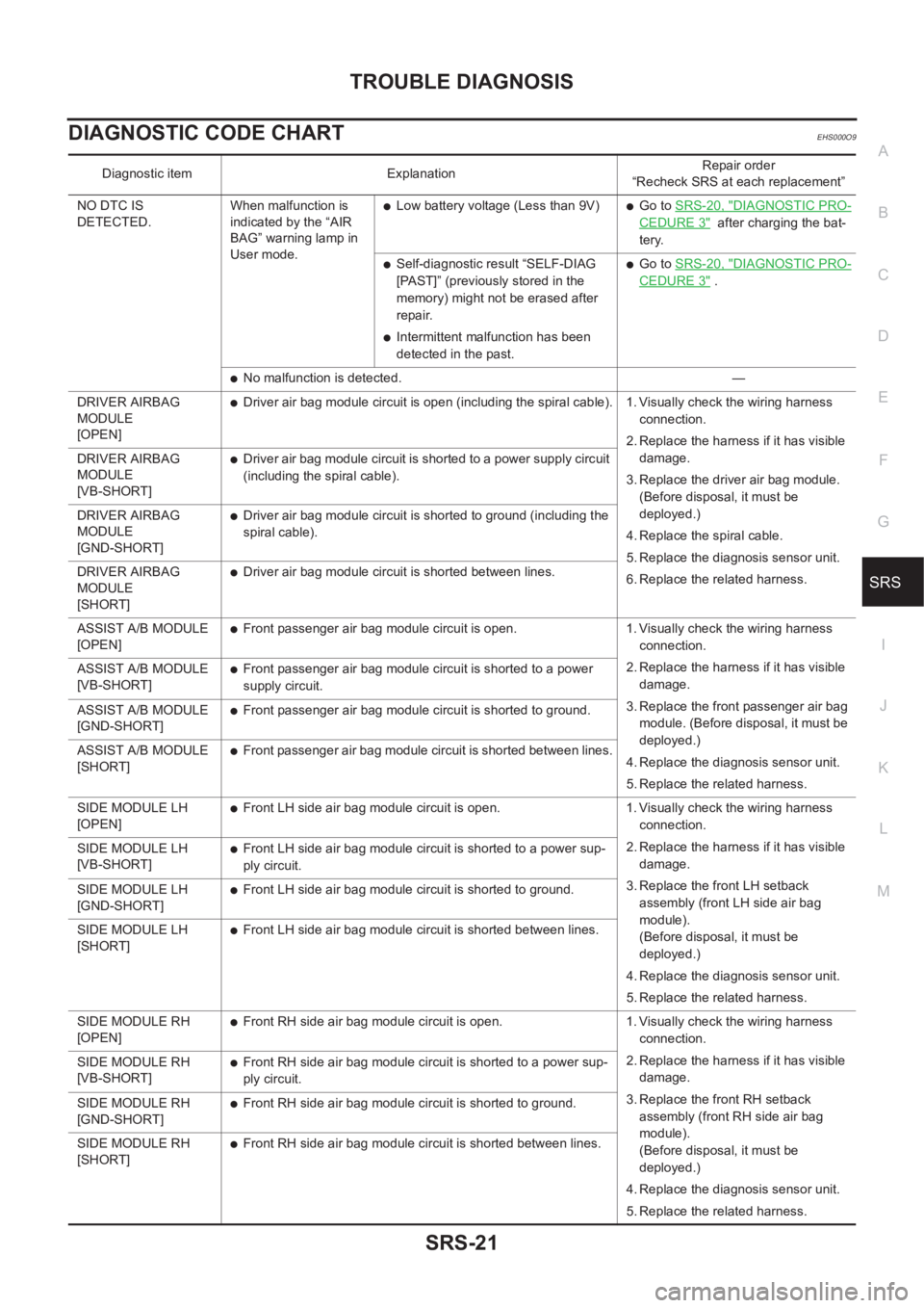
DIAGNOSTIC CODE CHARTEHS000O9
Diagnostic item ExplanationRepair order
“Recheck SRS at each replacement”
NO DTC IS
DETECTED.When malfunction is
indicated by the “AIR
BAG” warning lamp in
User mode.
●Low battery voltage (Less than 9V)●Go to SRS-20, "DIAGNOSTIC PRO-
CEDURE 3" after charging the bat-
tery.
●Self-diagnostic result “SELF-DIAG
[PAST]” (previously stored in the
memory) might not be erased after
repair.
●Intermittent malfunction has been
detected in the past.
●Go to SRS-20, "DIAGNOSTIC PRO-
CEDURE 3" .
●No malfunction is detected. —
DRIVER AIRBAG
MODULE
[OPEN]
●Driver air bag module circuit is open (including the spiral cable). 1. Visually check the wiring harness
connection.
2. Replace the harness if it has visible
damage.
3. Replace the driver air bag module.
(Before disposal, it must be
deployed.)
4. Replace the spiral cable.
5. Replace the diagnosis sensor unit.
6. Replace the related harness. DRIVER AIRBAG
MODULE
[VB-SHORT]
●Driver air bag module circuit is shorted to a power supply circuit
(including the spiral cable).
DRIVER AIRBAG
MODULE
[GND-SHORT]
●Driver air bag module circuit is shorted to ground (including the
spiral cable).
DRIVER AIRBAG
MODULE
[SHORT]
●Driver air bag module circuit is shorted between lines.
ASSIST A/B MODULE
[OPEN]
●Front passenger air bag module circuit is open. 1. Visually check the wiring harness
connection.
2. Replace the harness if it has visible
damage.
3. Replace the front passenger air bag
module. (Before disposal, it must be
deployed.)
4. Replace the diagnosis sensor unit.
5. Replace the related harness. ASSIST A/B MODULE
[VB-SHORT]
●Front passenger air bag module circuit is shorted to a power
supply circuit.
ASSIST A/B MODULE
[GND-SHORT]
●Front passenger air bag module circuit is shorted to ground.
ASSIST A/B MODULE
[SHORT]
●Front passenger air bag module circuit is shorted between lines.
SIDE MODULE LH
[OPEN]
●Front LH side air bag module circuit is open. 1. Visually check the wiring harness
connection.
2. Replace the harness if it has visible
damage.
3. Replace the front LH setback
assembly (front LH side air bag
module).
(Before disposal, it must be
deployed.)
4. Replace the diagnosis sensor unit.
5. Replace the related harness. SIDE MODULE LH
[VB-SHORT]
●Front LH side air bag module circuit is shorted to a power sup-
ply circuit.
SIDE MODULE LH
[GND-SHORT]
●Front LH side air bag module circuit is shorted to ground.
SIDE MODULE LH
[SHORT]
●Front LH side air bag module circuit is shorted between lines.
SIDE MODULE RH
[OPEN]
●Front RH side air bag module circuit is open. 1. Visually check the wiring harness
connection.
2. Replace the harness if it has visible
damage.
3. Replace the front RH setback
assembly (front RH side air bag
module).
(Before disposal, it must be
deployed.)
4. Replace the diagnosis sensor unit.
5. Replace the related harness. SIDE MODULE RH
[VB-SHORT]
●Front RH side air bag module circuit is shorted to a power sup-
ply circuit.
SIDE MODULE RH
[GND-SHORT]
●Front RH side air bag module circuit is shorted to ground.
SIDE MODULE RH
[SHORT]
●Front RH side air bag module circuit is shorted between lines.
Page 3040 of 3833
SRS-38
SIDE AIR BAG (SATELLITE) SENSOR
SIDE AIR BAG (SATELLITE) SENSOR
PFP:98830
Removal and InstallationEHS000DB
REMOVAL
CAUTION:
●Before servicing SRS, turn the ignition switch off, disconnect both battery cables and wait at least
3 minutes.
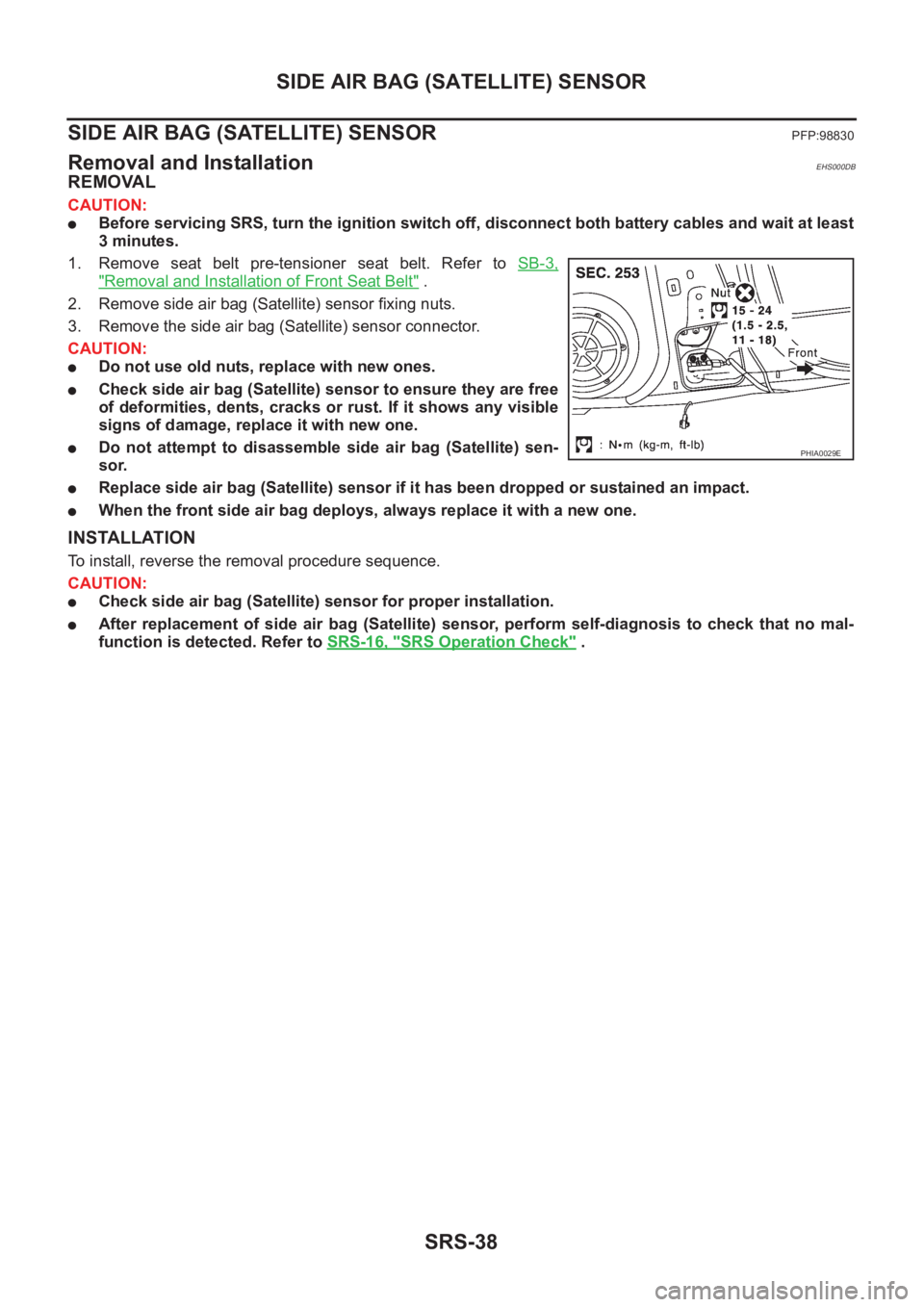
1. Remove seat belt pre-tensioner seat belt. Refer to SB-3,
"Removal and Installation of Front Seat Belt" .
2. Remove side air bag (Satellite) sensor fixing nuts.
3. Remove the side air bag (Satellite) sensor connector.
CAUTION:
●Do not use old nuts, replace with new ones.
●Check side air bag (Satellite) sensor to ensure they are free
of deformities, dents, cracks or rust. If it shows any visible
signs of damage, replace it with new one.
●Do not attempt to disassemble side air bag (Satellite) sen-
sor.
●Replace side air bag (Satellite) sensor if it has been dropped or sustained an impact.
●When the front side air bag deploys, always replace it with a new one.
INSTALLATION
To install, reverse the removal procedure sequence.
CAUTION:
●Check side air bag (Satellite) sensor for proper installation.
●After replacement of side air bag (Satellite) sensor, perform self-diagnosis to check that no mal-
function is detected. Refer to SRS-16, "
SRS Operation Check" .
PHIA0029E
Page 3042 of 3833
SRS-40
DIAGNOSIS SENSOR UNIT
DIAGNOSIS SENSOR UNIT
PFP:28556
Removal and InstallationEHS000DD
REMOVAL
CAUTION:
●Before servicing SRS, turn the ignition switch off, disconnect both battery cables and wait at least
3 minutes.
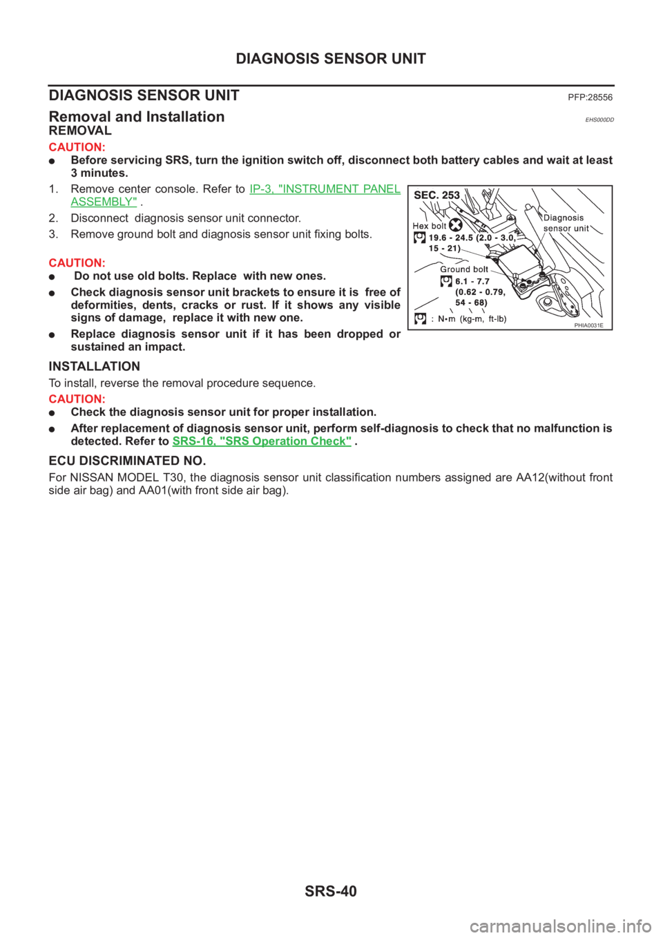
1. Remove center console. Refer to IP-3, "
INSTRUMENT PANEL
ASSEMBLY" .
2. Disconnect diagnosis sensor unit connector.
3. Remove ground bolt and diagnosis sensor unit fixing bolts.
CAUTION:
● Do not use old bolts. Replace with new ones.
●Check diagnosis sensor unit brackets to ensure it is free of
deformities, dents, cracks or rust. If it shows any visible
signs of damage, replace it with new one.
●Replace diagnosis sensor unit if it has been dropped or
sustained an impact.
INSTALLATION
To install, reverse the removal procedure sequence.
CAUTION:
●Check the diagnosis sensor unit for proper installation.
●After replacement of diagnosis sensor unit, perform self-diagnosis to check that no malfunction is
detected. Refer to SRS-16, "
SRS Operation Check" .
ECU DISCRIMINATED NO.
For NISSAN MODEL T30, the diagnosis sensor unit classification numbers assigned are AA12(without front
side air bag) and AA01(with front side air bag).
PHIA0031E
Page 3054 of 3833
BL-2
Power Supply and Ground Circuit Check ............... 60
Time Control Unit Lock Signal Circuit Check .......... 61
Time Control Unit Unlock Signal Circuit Check ...... 62
Hazard Reminder Check ........................................ 62
ID Code Entry Procedure ....................................... 63
Remote Controller Battery Replacement ................ 64
FRONT DOOR LOCK ............................................... 65
Component Parts Location ..................................... 65
Inspection and Adjustment ..................................... 65
OUT SIDE HANDLE ROD ADJUSTMENT .......... 65
Removal and Installation ........................................ 65
REMOVAL ........................................................... 65
INSTALLATION .................................................... 66
Disassembly and Assembly .................................... 67
DISASSEMBLY ................................................... 67
ASSEMBLY ......................................................... 67
REAR DOOR LOCK .................................................. 68
Component Parts Location ..................................... 68
Inspection and Adjustment ..................................... 68
OUT SIDE HANDLE ROD ADJUSTMENT .......... 68
Removal and Installation ........................................ 68
REMOVAL ........................................................... 68
INSTALLATION .................................................... 69
Disassembly and Assembly .................................... 70
DISASSEMBLY ................................................... 70
ASSEMBLY ......................................................... 70
BACK DOOR ............................................................. 71
Fitting Adjustment ................................................... 71
VERTICAL/LATERAL CLEARANCE ADJUST-
MENT .................................................................. 71
Back Door Assembly .............................................. 72
REMOVAL AND INSTALLATION ......................... 72
INSPECTION ....................................................... 72
Removal and Installation of Back Door Handle ...... 72
Removal and Installation of Back Door Lock and Actuator ................................................................... 73
Removal and Installation of Back Door Weatherstrip ... 73
FUEL FILLER LID OPENER ..................................... 75
Component Parts Location ..................................... 75
THEFT WARNING SYSTEM ..................................... 76
Wiring Diagram — THEFT —/PRI-WIRE ................ 76
LHD MODELS ...................................................... 76
RHD MODELS ..................................................... 78
NATS (NISSAN ANTI-THEFT SYSTEM) ................... 80
Component Parts and Harness Connector Location ... 80
System Description ................................................. 81
System Composition ............................................... 82
Wiring Diagram — NATS — .................................... 83
GASOLINE ENGINE MODELS ............................ 83
DIESEL ENGINE MODELS ................................. 84
CONSULT-II ............................................................ 85
CONSULT-II INSPECTION PROCEDURE .......... 85
CONSULT-II DIAGNOSTIC TEST MODE FUNC-
TION .................................................................... 85
HOW TO READ SELF-DIAGNOSTIC RESULTS ... 86
NATS SELF-DIAGNOSTIC RESULTS ITEM
CHART ................................................................. 86
Work Flow ............................................................... 88
Trouble Diagnoses .................................................. 89
SYMPTOM MATRIX CHART 1 ............................ 89
SYMPTOM MATRIX CHART 2 ............................ 90
DIAGNOSTIC SYSTEM DIAGRAM ..................... 90
Diagnostic Procedure 1 ........................................... 91
Diagnostic Procedure 2 ........................................... 91
Diagnostic Procedure 3 ........................................... 94
Diagnostic Procedure 4 ........................................... 95
Diagnostic Procedure 5 ........................................... 96
Diagnostic Procedure 6 ........................................... 97
Diagnostic Procedure 7 ........................................... 98
Diagnostic Procedure 8 ........................................... 99
How to Replace NATS IMMU ................................100
Page 3116 of 3833
BL-64
MULTI-REMOTE CONTROL SYSTEM
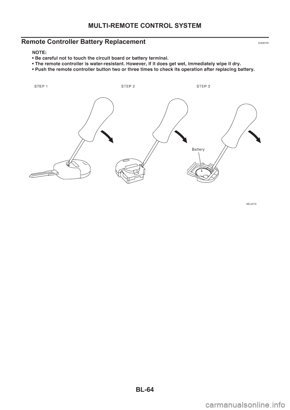
Remote Controller Battery Replacement
EIS001RI
SEL241X
Page 3692 of 3833
AV-4
AUDIO
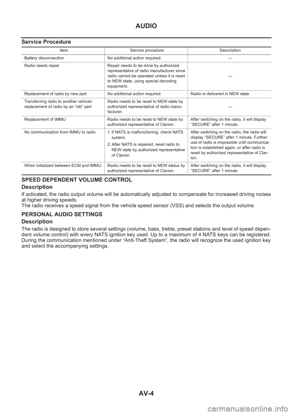
Service Procedure
SPEED DEPENDENT VOLUME CONTROL
Description
If activated, the radio output volume will be automatically adjusted to compensate for increased driving noises
at higher driving speeds.
The radio receives a speed signal from the vehicle speed sensor (VSS) and selects the output volume.
PERSONAL AUDIO SETTINGS
Description
The radio is designed to store several settings (volume, bass, treble, preset stations and level of speed depen-
dent volume control) with every NATS ignition key used. Up to a maximum of 4 NATS keys can be registered.
During the communication mentioned under “Anti-Theft System”, the radio will recognize the used ignition key
and select the accompanying settings.
Item Service procedure Description
Battery disconnection No additional action required. —
Radio needs repair Repair needs to be done by authorized
representative of radio manufacturer since
radio cannot be operated unless it is reset
to NEW state, using special decoding
equipment.—
Replacement of radio by new part No additional action required. Radio is delivered in NEW state.
Transferring radio to another vehicle/
replacement of radio by an “old” partRadio needs to be reset to NEW state by
authorized representative of radio manu-
facturer.—
Replacement of IMMU Radio needs to be reset to NEW state by
authorized representative of Clarion.After switching on the radio, it will display
“SECURE” after 1 minute.
No communication from IMMU to radio 1. If NATS is malfunctioning, check NATS
system.
2. After NATS is repaired, reset radio to
NEW state by authorized representative
of Clarion.After switching on the radio, the radio will
display “SECURE” after 1 minute. Further
use of radio is impossible until communica-
tion is established again, or after radio is
reset by authorized representative of Clar-
ion.
When initialized between ECM and IMMU. Radio needs to be reset to NEW status by
authorized representative of Clarion.After switching on the radio, it will display
“SECURE” after 1 minute.
Page 3826 of 3833

IDX-2
ALPHABETICAL INDEX
Numerics
4WD mode switch ................................... TF-54
,TF-57
4WD shift indicator lamp .................................... TF-55
4WD solenoid valve ................................ TF-49,TF-52
4WD warning lamp TF-40,TF-55,TF-56,TF-57,TF-58
A
A/C air flow ......................................... ATC-31
,MTC-5
A/C component layout ..................................... ATC-23
A/C compressor clutch removal and installation ...........
ATC-135
A/C compressor precaution ............................... ATC-9
A/C compressor special service tool ................ ATC-14
A/C diagnostic work flow (auto A/C) ................ ATC-33
A/C HFC134a (R134a) system precaution ........ ATC-4
A/C HFC134a (R134a) system service procedure .......
ATC-129
A/C HFC134a (R134a) system service tools ... ATC-15
A/C HFC134a system service equipment precaution ...
ATC-10
A/C lubricant (R134a) ...................................... ATC-24
A/C operational check ......................... ATC-54,MTC-7
A/C performance test diagnoses ..................... ATC-88
A/C reray .......................................................... ATC-84
A/C self-diagnoses (auto A/C) ......................... ATC-46
A/C system description (auto A/C) ................... ATC-27
A/C trouble diagnoses (auto A/C) ....... ATC-33,MTC-3
A/C, A - Wiring diagram ................................... ATC-38
A/CCUT - Wiring diagram .............................. EC-1572
A/T - Wiring diagram - AT - FTS ...................... AT-118
A/T - Wiring diagram - AT - MAIN .................... AT-350
A/T - Wiring diagram - AT - PNP/SW ............... AT-112
A/T - Wiring diagram - AT - VSS A/T . AT-124,AT-355
A/T fluid checking .................................. AT-13,MA-36
A/T fluid replacement ............................. AT-13,MA-36
A/T fluid temperature sensor ........................... AT-121
A/T IND - Wiring diagram .................................... DI-57
A/T indicator ........................................................ DI-57
A/T shift lock system ........................................ AT-406
A/T shift lock system - Wiring diagram ............ AT-407
A/T trouble diagnoses .......................... AT-56,AT-258
A/T Wiring diagram - AT - ENG SS ... AT-128,AT-393
A/T Wiring diagram AT - 1ST ........................... AT-134
A/T Wiring diagram AT - 2ND .......................... AT-140
A/T Wiring diagram AT - 3RD .......................... AT-146
A/T Wiring diagram AT - 4TH .......................... AT-152
A/T Wiring diagram AT - BA/FTS ....... AT-195,AT-388
A/T Wiring diagram AT - CAN ............ AT-191,AT-404
A/T Wiring diagram AT - LPSV .......... AT-165,AT-398
A/T Wiring diagram AT - OVRCSV .... AT-187,AT-378
A/T Wiring diagram AT - SSV/A ......... AT-172,AT-369
A/T Wiring diagram AT - SSV/B ......... AT-177,AT-374
A/T Wiring diagram AT - TCV ............ AT-160,AT-383
A/T Wiring diagram AT - TPS ............ AT-182,AT-364
A/T Wiring diagrawm AT - VSSMTR .. AT-201,AT-360
ABS - Wiring diagram ..................................... BRC-12
Absolute pressure sensor .............................. EC-1494
Accelerator control system ............................... ACC-2
Accelerator pedal position (APP) sensor ........ EC-355,
EC-361
,EC-373,EC-631,EC-637,EC-651,EC-893,
EC-1222
,EC-1460
Accelerator pedal released position learning . EC-1404
Accelerator pedal released position switch .... EC-1531
Actuator relay ..................................................... TF-52
Aiming adjustment ............................................... LT-4
Air bag .............................................................. SRS-3
Air bag disposal .............................................. SRS-41
Air bleeding (hydraulic clutch) .............................. CL-8
Air bleeding for brake system ............................ BR-10
Air cleaner and air duct(QR20DE•QR25DE) .... EM-14
Air cleaner and air duct(YD22DDTi) ............... EM-120
Air cleaner filter replacement(QR20DE•QR25DE) ........
MA-22
Air cleaner filter replacement(YD22DDTi) ......... MA-32
Air cleaner filter(QR20DE•QR25DE) ................ EM-14
Air cleaner filter(YD22DDTi) ........................... EM-120
Air conditioner cut control .... EC-36,EC-446,EC-768,
EC-1132
,EC-1401
Air flow meter - See Mass air flow sensor ....... EC-138,
EC-516
,EC-870,EC-999,EC-1202
Air mix door control linkage adjustment ......... ATC-66,
ATC-125
,MTC-10,MTC-28
Air mix. door motor ......................... ATC-64,ATC-125
Air spoiler, rear ................................................... EI-21
Alternator ........................................................... SC-12
Ambient sensor ............. ATC-100,ATC-102,ATC-112
Angular tightening application(QR20DE•QR25DE) ......
EM-5
Angular tightening application(YD22DDTi) ..... EM-110
Antenna - See Power antenna ........................... AV-16
APPS - Wiring diagram ... EC-895,EC-1225,EC-1462
APPS1 - Wiring diagram ................... EC-357,EC-633
APPS2 - Wiring diagram ................... EC-363,EC-640
APPS3 - Wiring diagram ................... EC-375,EC-653
APRSW - Wiring diagram .............................. EC-1533
Audio .................................................................... AV-3
Auto air conditioner - Wiring diagram ............. ATC-38
Automatic amplifier ........................... ATC-44,ATC-57
Automatic transmission fluid replacement ....... MA-35,
MA-37
Axle ................................................................... MA-41
B
Back door ........................................................... BL-71
Back door trim ..................................................... EI-25
Back door window .............................................. GW-8
Back window ...................................................... GW-8
BACK/L - Wiring diagram ................................... LT-28
Back-up lamp .......................................... LT-28,LT-42
Back-up lamp switch (M/T) ............................... MT-12
Basic inspection ... EC-73,EC-465,EC-805,EC-1152,
EC-1412
Battery ................................................................. SC-3
Baulk ring (M/T) .................................... MT-18,MT-23
Blower motor ..... ATC-70,ATC-77,ATC-118,MTC-14,