instrument panel NISSAN X-TRAIL 2003 Electronic Repair Manual
[x] Cancel search | Manufacturer: NISSAN, Model Year: 2003, Model line: X-TRAIL, Model: NISSAN X-TRAIL 2003Pages: 3066, PDF Size: 51.47 MB
Page 1 of 3066
MODEL T30 SERIES
2001 NISSAN EUROPE N.V.
All rights reserved. No part of this Electronic Service Manual may be reproduced or stored in a retrieval system, or transmitted in any
form, or by any means, electronic, mechanical, photocopying, recording or otherwise, without the prior written permission of Nissan
Europe N.V., Paris, France.
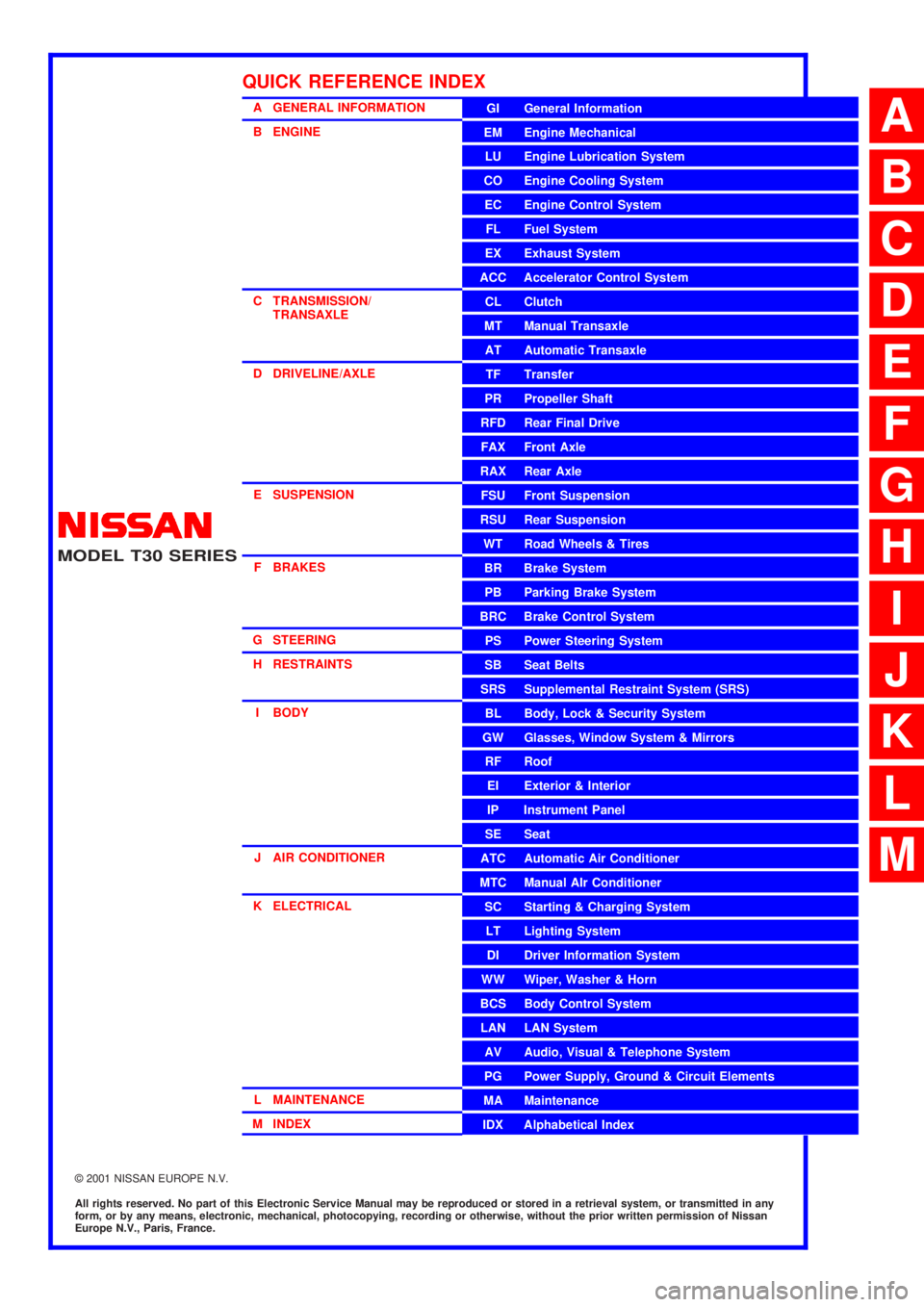
A GENERAL INFORMATION
B ENGINE
C TRANSMISSION/
TRANSAXLE
D DRIVELINE/AXLE
E SUSPENSION
F BRAKES
G STEERING
H RESTRAINTS
I BODY
J AIR CONDITIONER
K ELECTRICAL
L MAINTENANCE
M INDEXGI General Information
EM Engine Mechanical
LU Engine Lubrication System
CO Engine Cooling System
EC Engine Control System
FL Fuel System
EX Exhaust System
ACC Accelerator Control System
CL Clutch
MT Manual Transaxle
AT Automatic Transaxle
TF Transfer
PR Propeller Shaft
RFD Rear Final Drive
FAX Front Axle
RAX Rear Axle
FSU Front Suspension
RSU Rear Suspension
WT Road Wheels & Tires
BR Brake System
PB Parking Brake System
BRC Brake Control System
PS Power Steering System
SB Seat Belts
SRS Supplemental Restraint System (SRS)
BL Body, Lock & Security System
GW Glasses, Window System & Mirrors
RF Roof
EI Exterior & Interior
IP Instrument Panel
SE Seat
ATC Automatic Air Conditioner
MTC Manual AIr Conditioner
SC Starting & Charging System
LT Lighting System
DI Driver Information System
WW Wiper, Washer & Horn
BCS Body Control System
LAN LAN System
AV Audio, Visual & Telephone System
PG Power Supply, Ground & Circuit Elements
MA Maintenance
IDX Alphabetical Index
QUICK REFERENCE INDEX
A
B
C
D
E
F
G
H
I
J
K
L
M
Page 43 of 3066
![NISSAN X-TRAIL 2003 Electronic Repair Manual ON BOARD DIAGNOSTIC SYSTEM DESCRIPTION
AT-37
[EURO-OBD]
D
E
F
G
H
I
J
K
L
MA
B
AT
ON BOARD DIAGNOSTIC SYSTEM DESCRIPTIONPFP:00000
IntroductionECS004QH
The A/T system has two self-diagnostic systems.
T NISSAN X-TRAIL 2003 Electronic Repair Manual ON BOARD DIAGNOSTIC SYSTEM DESCRIPTION
AT-37
[EURO-OBD]
D
E
F
G
H
I
J
K
L
MA
B
AT
ON BOARD DIAGNOSTIC SYSTEM DESCRIPTIONPFP:00000
IntroductionECS004QH
The A/T system has two self-diagnostic systems.
T](/img/5/57402/w960_57402-42.png)
ON BOARD DIAGNOSTIC SYSTEM DESCRIPTION
AT-37
[EURO-OBD]
D
E
F
G
H
I
J
K
L
MA
B
AT
ON BOARD DIAGNOSTIC SYSTEM DESCRIPTIONPFP:00000
IntroductionECS004QH
The A/T system has two self-diagnostic systems.
The first is the emission-related on board diagnostic system (EURO-OBD) performed by the TCM in combina-
tion with the ECM. The malfunction is indicated by the MIL (malfunction indicator lamp) and is stored as a DTC
in the ECM memory but not the TCM memory.
The second is the TCM original self-diagnosis indicated by the O/D OFF indicator lamp. The malfunction is
stored in the TCM memory. The detected items are overlapped with EURO-OBD self-diagnostic items. For
detail, refer toAT - 4 2 , "
SELF-DIAGNOSTIC RESULT TEST MODE".
EURO-OBD Function for A/T SystemECS004QI
The ECM provides emission-related on board diagnostic (EURO-OBD) functions for the A/T system. One
function is to receive a signal from the TCM used with EURO-OBD-related parts of the A/T system. The signal
is sent to the ECM when a malfunction occurs in the corresponding EURO-OBD-related part. The other func-
tion is to indicate a diagnostic result by means of the MIL (malfunction indicator lamp) on the instrument panel.
Sensors, switches and solenoid valves are used as sensing elements.
The MIL automatically illuminates in One or Two Trip Detection Logic when a malfunction is sensed in relation
to A/T system parts.
One or Two Trip Detection Logic of EURO-OBDECS0 04 QJ
ONETRIPDETECTIONLOGIC
If a malfunction is sensed during the first test drive, the MIL will illuminate and the malfunction will be stored in
the ECM memory as a DTC. The TCM is not provided with such a memory function.
TWO TRIP DETECTION LOGIC
When a malfunction is sensed during the first test drive, it is stored in the ECM memory as a 1st trip DTC
(diagnostic trouble code) or 1st trip freeze frame data. At this point, the MIL will not illuminate. — First Trip
If the same malfunction as that experienced during the first test drive is sensed during the second test drive,
the MIL will illuminate. — Second Trip
A/T-related parts for which the MIL illuminates during the first or second test drive are listed below.
The “trip” in the “One or Two Trip Detection Logic” means a driving mode in which self-diagnosis is performed
during vehicle operation.
EURO-OBD Diagnostic Trouble Code (DTC)ECS004QK
HOW TO READ DTC AND 1ST TRIP DTC
DTC and 1st trip DTC can be read by the following methods.
(withCONSULT-IIor GST)CONSULT-II or GST (Generic Scan Tool) Examples: P0705, P0710,
P0720, P0725, etc.
These DTCs are prescribed by SAE J2012.
(CONSULT-II also displays the malfunctioning component or system.)
l1st trip DTC No. is the same as DTC No.
lOutput of the diagnostic trouble code indicates that the indicated circuit has a malfunction. How-
ever, in case of the Mode II and GST they do not indicate whether the malfunction is still occurring
or occurred in the past and returned to normal.
CONSULT-II can identify them as shown below. Therefore, using CONSULT-II (if available) is rec-
ommended.
ItemsMIL
One trip detection Two trip detection
Shift solenoid valve A — DTC: P0750 X
Shift solenoid valve B — DTC: P0755 X
Throttle position sensor — DTC: P1705 X
Except aboveX
Page 673 of 3066
TROUBLE DIAGNOSIS
ATC-95
C
D
E
F
G
H
I
K
L
MA
B
AT C
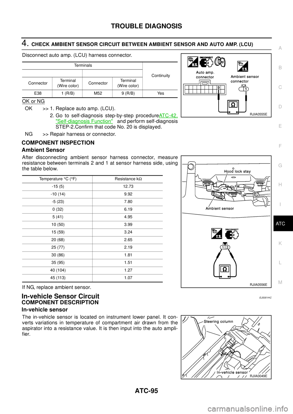
4.CHECK AMBIENT SENSOR CIRCUIT BETWEEN AMBIENT SENSOR AND AUTO AMP. (LCU)
Disconnect auto amp. (LCU) harness connector.
OK or NG
OK >> 1. Replace auto amp. (LCU).
2. Go to self-diagnosis step-by-step procedureAT C - 4 2 ,
"Self-diagnosis Function"and perform self-diagnosis
STEP-2.Confirm that code No. 20 is displayed.
NG >> Repair harness or connector.
COMPONENT INSPECTION
Ambient Sensor
After disconnecting ambient sensor harness connector, measure
resistance between terminals 2 and 1 at sensor harness side, using
the table below.
If NG, replace ambient sensor.
In-vehicle Sensor CircuitEJS001HC
COMPONENT DESCRIPTION
In-vehicle sensor
The in-vehicle sensor is located on instrument lower panel. It con-
verts variations in temperature of compartment air drawn from the
aspirator into a resistance value. It is then input into the auto ampli-
fier.
Te r m i n a l s
Continuity
ConnectorTe r m i n a l
(Wire color)ConnectorTerminal
(Wire color)
E38 1 (R/B) M52 9 (R/B) Yes
RJIA0555E
Temperature°C(°F) Resistance kW
-15 (5) 12.73
-10 (14) 9.92
-5 (23) 7.80
0(32) 6.19
5(41) 4.95
10 (50) 3.99
15 (59) 3.24
20 (68) 2.65
25 (77) 2.19
30 (86) 1.81
35 (95) 1.51
40 (104) 1.27
45 (113) 1.07
RJIA0556E
RJIA0049E
Page 687 of 3066
BLOWER UNIT
ATC-109
C
D
E
F
G
H
I
K
L
MA
B
AT C
BLOWER UNITPFP:27200
Removal and InstallationEJS000UL
REMOVAL
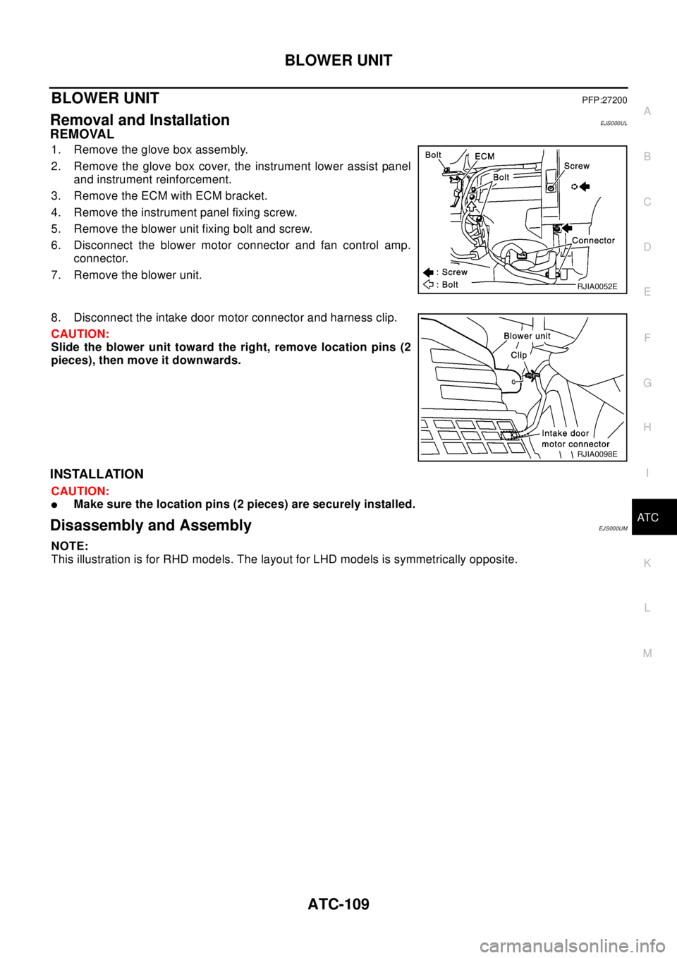
1. Remove the glove box assembly.
2. Remove the glove box cover, the instrument lower assist panel
and instrument reinforcement.
3. Remove the ECM with ECM bracket.
4. Remove the instrument panel fixing screw.
5. Remove the blower unit fixing bolt and screw.
6. Disconnect the blower motor connector and fan control amp.
connector.
7. Remove the blower unit.
8. Disconnect the intake door motor connector and harness clip.
CAUTION:
Slide the blower unit toward the right, remove location pins (2
pieces), then move it downwards.
INSTALLATION
CAUTION:
lMake sure the location pins (2 pieces) are securely installed.
Disassembly and AssemblyEJS000UM
NOTE:
This illustration is for RHD models. The layout for LHD models is symmetrically opposite.
RJIA0052E
RJIA0098E
Page 693 of 3066
HEATER & COOLING UNIT ASSEMBLY
ATC-115
C
D
E
F
G
H
I
K
L
MA
B
AT C
HEATER & COOLING UNIT ASSEMBLYPFP:27110
Removal and InstallationEJS000UT
REMOVAL
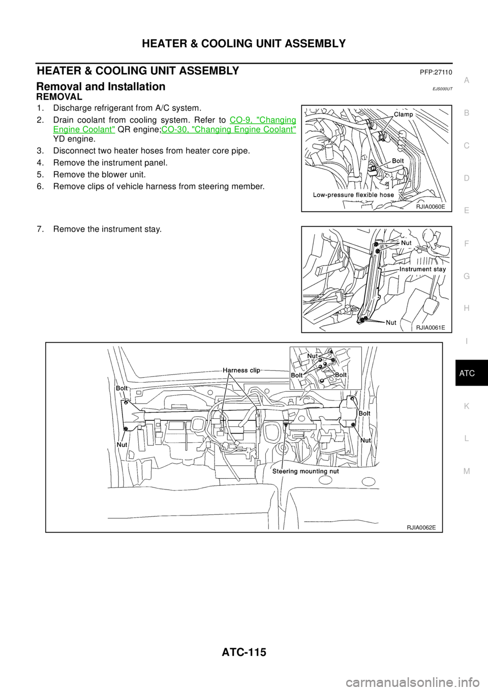
1. Discharge refrigerant from A/C system.
2. Drain coolant from cooling system. Refer toCO-9, "
Changing
Engine Coolant"QR engine;CO-30, "Changing Engine Coolant"
YD engine.
3. Disconnect two heater hoses from heater core pipe.
4. Remove the instrument panel.
5. Remove the blower unit.
6. Remove clips of vehicle harness from steering member.
7. Remove the instrument stay.
RJIA0060E
RJIA0061E
RJIA0062E
Page 699 of 3066
DUCTS AND GRILLES
ATC-121
C
D
E
F
G
H
I
K
L
MA
B
AT C
DUCTS AND GRILLESPFP:27860
Removal and InstallationEJS000UX
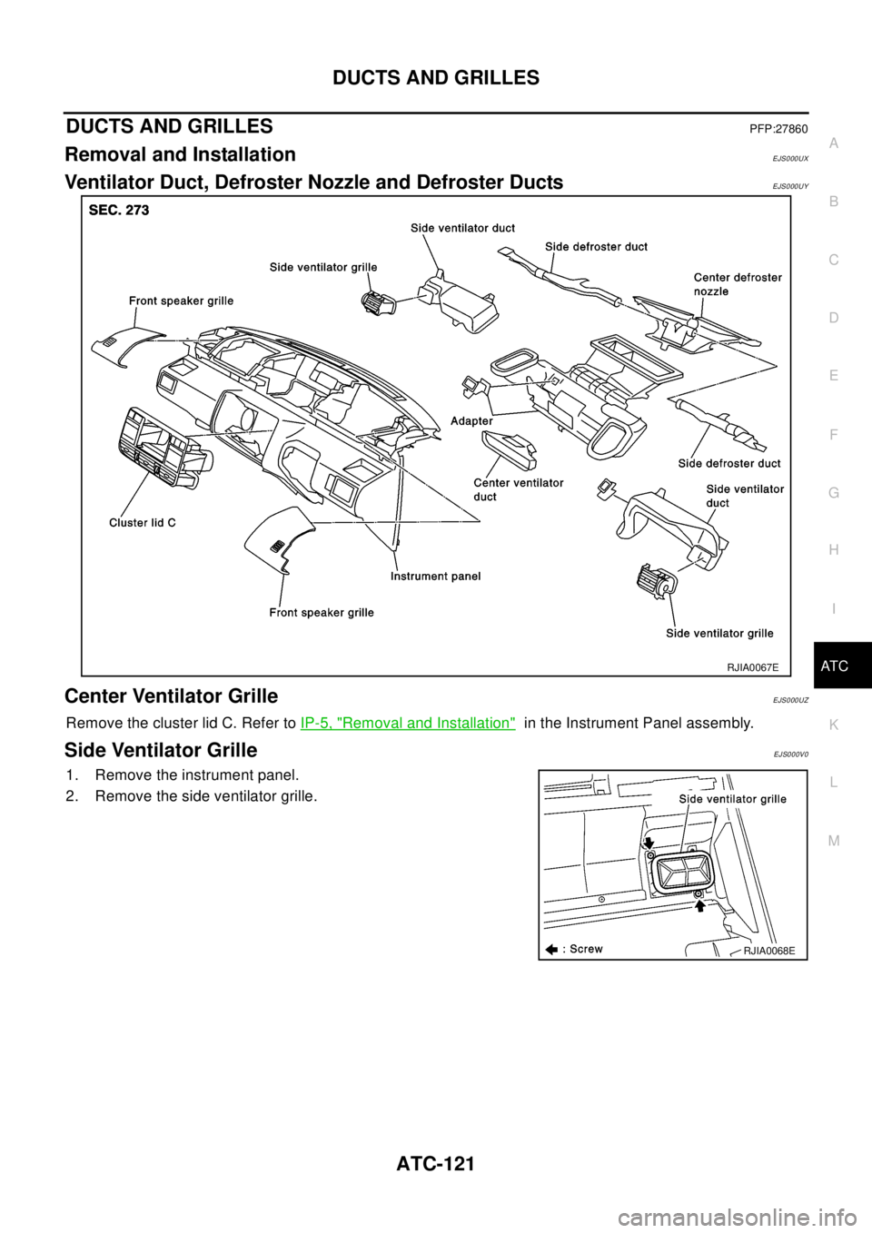
Ventilator Duct, Defroster Nozzle and Defroster DuctsEJS000UY
Center Ventilator GrilleEJS000UZ
Remove the cluster lid C. Refer toIP-5, "Removal and Installation"in the Instrument Panel assembly.
Side Ventilator GrilleEJS000V0
1. Remove the instrument panel.
2. Remove the side ventilator grille.
RJIA0067E
RJIA0068E
Page 700 of 3066
ATC-122
DUCTS AND GRILLES
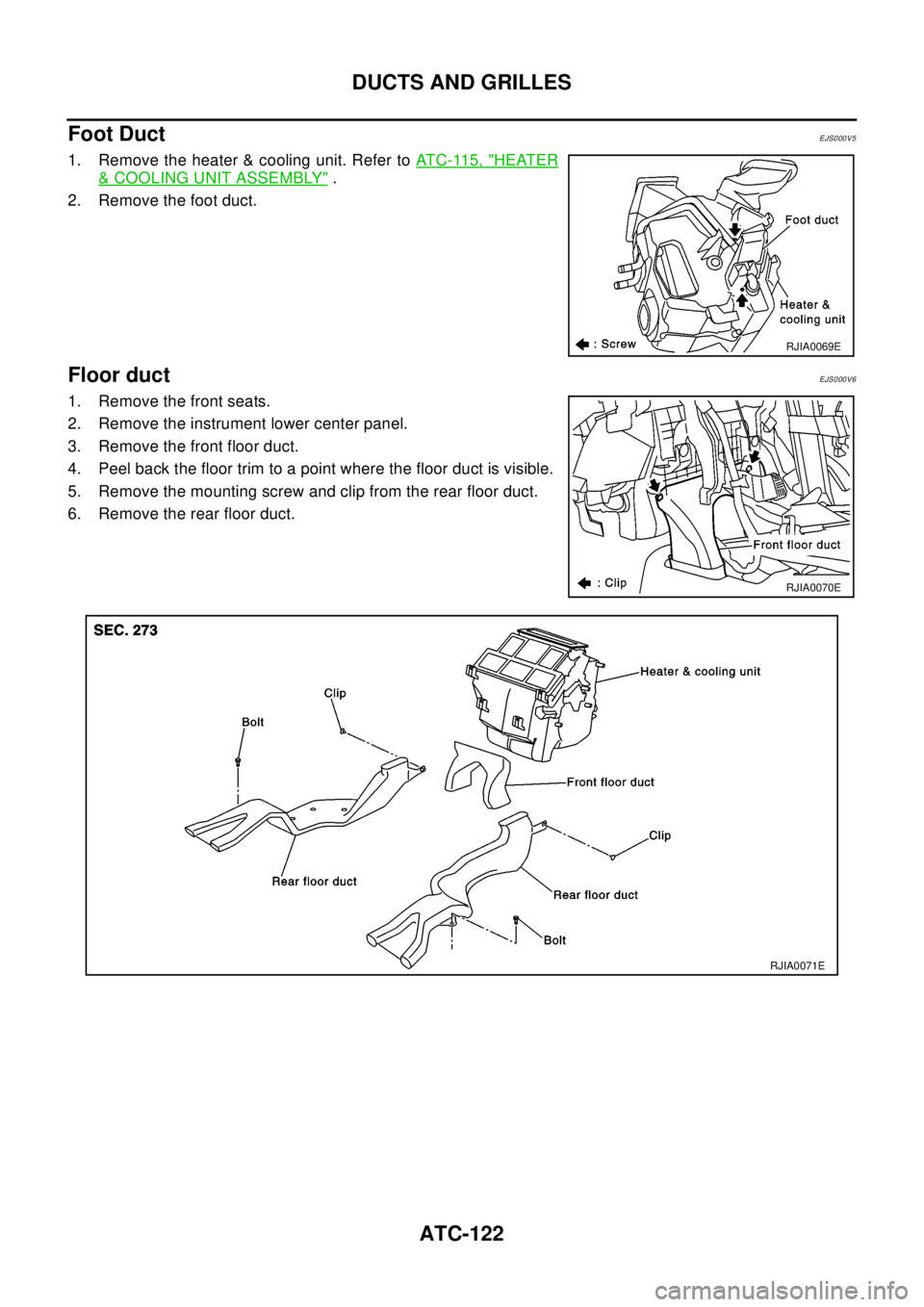
Foot Duct
EJS000V5
1. Remove the heater & cooling unit. Refer toATC-115, "HEATER
&COOLING UNIT ASSEMBLY".
2. Remove the foot duct.
Floor ductEJS000V6
1. Remove the front seats.
2. Remove the instrument lower center panel.
3. Remove the front floor duct.
4. Peel back the floor trim to a point where the floor duct is visible.
5. Remove the mounting screw and clip from the rear floor duct.
6. Remove the rear floor duct.
RJIA0069E
RJIA0070E
RJIA0071E
Page 735 of 3066
AUDIO
AV-13
C
D
E
F
G
H
I
J
L
MA
B
AV
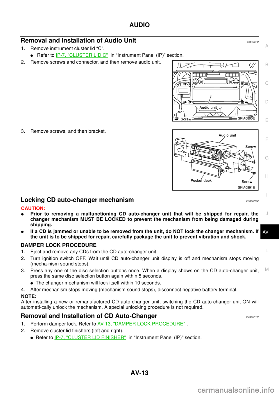
RemovalandInstallationofAudioUnitEKS002PU
1. Remove instrument cluster lid “C”.
lRefer toIP-7, "CLUSTER LID C"in “Instrument Panel (IP)” section.
2. Remove screws and connector, and then remove audio unit.
3. Remove screws, and then bracket.
Locking CD auto-changer mechanismEKS002GM
CAUTION:
lPrior to removing a malfunctioning CD auto-changer unit that will be shipped for repair, the
changer mechanism MUST BE LOCKED to prevent the mechanism from being damaged during
shipping.
lIf a CD is jammed or unable to be removed from the unit, do NOT lock the changer mechanism. If
the unit is to be shipped for repair, carefully package the unit to prevent vibration and shock.
DAMPER LOCK PROCEDURE
1. Eject and remove any CDs from the CD auto-changer unit.
2. Turn ignition switch OFF. Wait until CD auto-changer unit display is off and mechanism stops moving
(mecha-nism sound stops).
3. Press any one of the disc selection buttons once. When a display shows on the CD auto-changer unit,
press the same disc selection button again within 5 seconds.
lThe changer mechanism will lock itself within 10 seconds.
4. After mechanism stops moving (mechanism sound stops), disconnect negative battery terminal.
NOTE:
After installing a new or remanufactured CD auto-changer unit, switching the CD auto-changer unit ON will
automati-cally unlock the mechanism. A special unlocking procedure is not required.
Removal and Installation of CD Auto-ChangerEKS002UW
1. Perform damper lock. Refer toAV- 1 3 , "DAMPER LOCK PROCEDURE".
2. Remove cluster lid finishers (left and right).
lRefer toIP-7, "CLUSTER LID FINISHER"in “Instrument Panel (IP)” section.
SKIA0890E
SKIA0891E
Page 841 of 3066
BRAKE PEDAL
BR-7
C
D
E
G
H
I
J
K
L
MA
B
BR
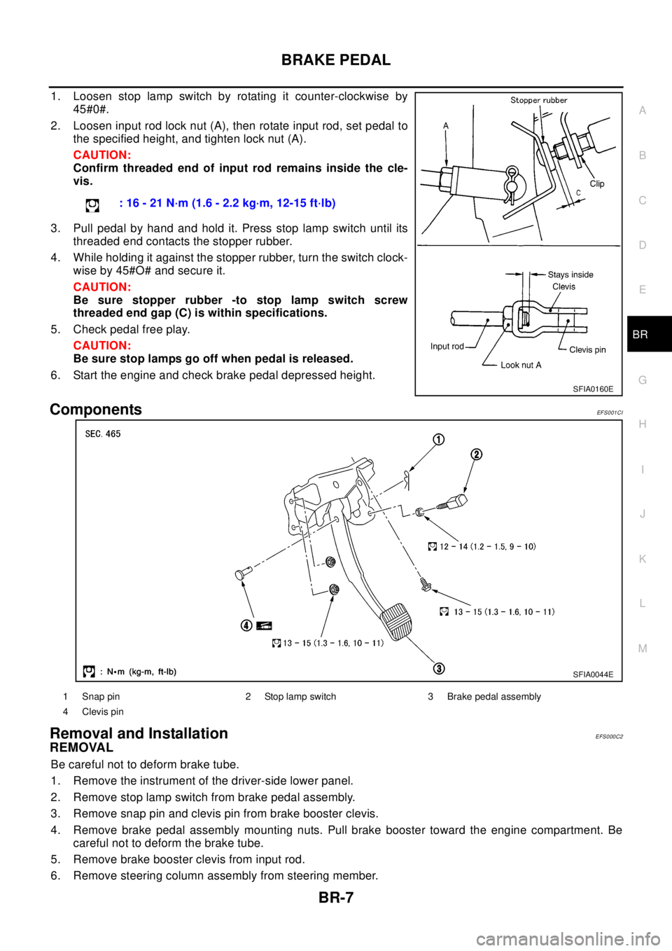
1. Loosen stop lamp switch by rotating it counter-clockwise by
45#0#.
2. Loosen input rod lock nut (A), then rotate input rod, set pedal to
the specified height, and tighten lock nut (A).
CAUTION:
Confirm threaded end of input rod remains inside the cle-
vis.
3. Pull pedal by hand and hold it. Press stop lamp switch until its
threaded end contacts the stopper rubber.
4. While holding it against the stopper rubber, turn the switch clock-
wise by 45#O# and secure it.
CAUTION:
Be sure stopper rubber -to stop lamp switch screw
threaded end gap (C) is within specifications.
5. Check pedal free play.
CAUTION:
Be sure stop lamps go off when pedal is released.
6. Start the engine and check brake pedal depressed height.
ComponentsEF S0 01 CI
Removal and InstallationEFS000C2
REMOVAL
Be careful not to deform brake tube.
1. Remove the instrument of the driver-side lower panel.
2. Remove stop lamp switch from brake pedal assembly.
3. Remove snap pin and clevis pin from brake booster clevis.
4. Remove brake pedal assembly mounting nuts. Pull brake booster toward the engine compartment. Be
careful not to deform the brake tube.
5. Remove brake booster clevis from input rod.
6. Remove steering column assembly from steering member.: 16 - 21 N·m (1.6 - 2.2 kg·m, 12-15 ft·lb)
SFIA0160E
SFIA0044E
1 Snap pin 2 Stop lamp switch 3 Brake pedal assembly
4 Clevis pin
Page 917 of 3066
![NISSAN X-TRAIL 2003 Electronic Repair Manual G-SENSOR (4WD MODEL ONLY)
BRC-49
[4WD/ABS]
C
D
E
G
H
I
J
K
L
MA
B
BRC
G-SENSOR (4WD MODEL ONLY)PFP:47930
Removal and InstallationEFS001C2
CAUTION:
Be careful not to drop or bump G -sensor because it i NISSAN X-TRAIL 2003 Electronic Repair Manual G-SENSOR (4WD MODEL ONLY)
BRC-49
[4WD/ABS]
C
D
E
G
H
I
J
K
L
MA
B
BRC
G-SENSOR (4WD MODEL ONLY)PFP:47930
Removal and InstallationEFS001C2
CAUTION:
Be careful not to drop or bump G -sensor because it i](/img/5/57402/w960_57402-916.png)
G-SENSOR (4WD MODEL ONLY)
BRC-49
[4WD/ABS]
C
D
E
G
H
I
J
K
L
MA
B
BRC
G-SENSOR (4WD MODEL ONLY)PFP:47930
Removal and InstallationEFS001C2
CAUTION:
Be careful not to drop or bump G -sensor because it is sensitive to impact.
1. Remove center console and instrument. Refer to applicable sec-
tion inIP-3, "
INSTRUMENT PANEL ASSEMBLY".
2. Disconnect G -sensor connector.
3. Remove mounting nuts and remove G -sensor.
Install in the reverse order of removal observing the precautions
above.
SFIA0065E