remote control NISSAN X-TRAIL 2003 Electronic Repair Manual
[x] Cancel search | Manufacturer: NISSAN, Model Year: 2003, Model line: X-TRAIL, Model: NISSAN X-TRAIL 2003Pages: 3066, PDF Size: 51.47 MB
Page 743 of 3066

TIME CONTROL UNIT
BCS-5
C
D
E
F
G
H
I
J
L
MA
B
BCS
Time Control Unit Inspection TableEKS002ZW
Te r m i n a l
No.Wire
colorConnections Operation conditionVo l ta g e
(Approxi-
mate values)
1 L/B Power source (Fuse) — 12V
3 L/Y Super lock actuator Door key cylinder switchFree 0V
Unlocked 12V
4G/RPassenger and rear doors lock
actuatorDoor lock/unlock switchFree 0V
Unlocked 12V
6 Y/R Super lock actuator Door key cylinder switchFree 0V
Locked 12V
10 W Power source (C/B) — 12V
11 L Driver's door lock actuator Door lock/unlock switchFree 0V
Unlocked 12V
14 R/B Door lock actuator Door lock/unlock switchFree 0V
Locked 12V
16 B Ground — 0V
17 G Ignition switch (ON) — 12V
18 W/L Ignition key switch (Insert) Key inserted®key removed from IGN key cylinder 12V®0V
19 R/L Lighting switch 1ST, 2ND position: ON®OFF 12V®0V
20 GY Door lock/Unlock switch Neutral®Locks 5V®0V
23 PU Door lock/Unlock switch Neutral®Unlocks 5V®0V
24 OR/L Door key cylinder switch OFF (Neutral)®ON (Locked) 5V®0V
25 W/L Door key cylinder switch OFF (Neutral)®ON (Unlocked) 5V®0V
26 R/Y Interior room lampWhen interior room lamp is operated using remote control-
ler (Lamp switch is “DOOR” position)12V®0V
27 G/W Rear window defogger relay OFF®ON (Ignition key is in “ON” position) 12V®0V
28 Y/G Driver door unlock sensor Driver door: Locked®Unlocked 5V®0V
29 Y/L Passenger door unlock sensor Passenger door: Locked®Unlocked 5V®0V
30 R Doorswitchdriverside OFF(closed)®ON (open) 5V®0V
31 R/W Passenger and rear doors switch OFF (closed)®ON (open) 5V®0V
32 OR Multi-remote control unitRemote controller lock button is pushed.
(Ignition switch is not at “ON” position)0V®5V
33 P/L Multi-remote control unitRemote controller unlock button is pushed.
(Ignition switch is not at “ON” position)0V®5V
35 LG/B Rear window defogger switch OFF®ON 5V®0V
Page 745 of 3066

BL-1
BODY, LOCK & SECURITY SYSTEM
IBODY
CONTENTS
C
D
E
F
G
H
J
K
L
M
SECTION
A
B
BL
BODY, LOCK & SECURITY SYSTEM
PRECAUTIONS .......................................................... 3
Precautions .............................................................. 3
HOOD ......................................................................... 4
Fitting Adjustment .................................................... 4
FRONT END HEIGHT ADJUSTMENT AND LAT-
ERAL/LONGITUDIAL CLEARANCE ADJUST-
MENT .................................................................... 4
SURFACE HEIGHT ADJUSTMENT ..................... 4
Removal and Installation of Hood Assembly ............ 5
Removal and Installation of Hood Lock Control ....... 6
REMOVAL ............................................................. 6
INSTALLATION ..................................................... 7
Hood Lock Control Inspection .................................. 7
DOOR ......................................................................... 8
Fitting Adjustment .................................................... 8
FRONT DOOR ...................................................... 8
REAR DOOR ........................................................ 8
STRIKER ADJUSTMENT ..................................... 9
Removal and Installation .......................................... 9
Door Weatherstrip .................................................. 10
POWER DOOR LOCK SYSTEM ...............................11
System Description .................................................11
OPERATION ........................................................11
Component Parts and Harness Connector Location....11
Schematic .............................................................. 12
Wiring Diagram — D/LOCK — ............................... 13
Terminal and Reference Value for Time Control Unit... 17
Symptom Chart ...................................................... 17
Power Supply and Ground Circuit Check ............... 18
Door Lock/Unlock Switch Check ............................ 18
Door Key Cylinder Switch Check ........................... 19
Door Lock Actuator Check ..................................... 20
Door Switch Check ................................................. 21
Door Unlock Sensor Check .................................... 22
Key Switch Check .................................................. 23
POWER DOOR LOCK — SUPER LOCK — ............ 24
System Description ................................................ 24
OUTLINE ............................................................. 24
OPERATION ....................................................... 24
Schematic .............................................................. 26Wiring Diagram — S/LOCK — ............................... 27
Terminal and Reference Value for Time Control Unit... 33
Trouble Diagnoses ................................................. 34
PRELIMINARY CHECK ....................................... 34
SYMPTOM CHART ............................................. 35
Power Supply and Ground Circuit Check ............... 36
Door Lock/Unlock Switch Check ............................ 36
Door Key Cylinder Switch Check ............................ 37
Door Lock Actuator Check ...................................... 38
Door Switch Check ................................................. 39
Door Unlock Sensor Check .................................... 40
Key Switch Check ................................................... 41
Super Lock Actuator Check .................................... 42
NATS Release Signal Check .................................. 43
Ignition Switch “ON” Circuit Check ......................... 44
Remote Controller Signal Check ............................ 44
MULTI-REMOTE CONTROL SYSTEM ..................... 45
Component Parts and Harness Connector Location... 45
System Description ................................................. 45
FUNCTION .......................................................... 45
LOCK OPERATION ............................................. 45
UNLOCK OPERATION ........................................ 46
HAZARD REMINDER ......................................... 46
MULTI-REMOTE CONTROLLER ID CODE
ENTRY ................................................................ 46
Wiring Diagram — MULTI — .................................. 47
Terminal and Reference Value for Multi-remote
Control Unit ............................................................. 49
Symptom Chart ....................................................... 49
Remote Controller Battery Check ........................... 49
Power Supply and Ground Circuit Check ............... 50
Hazard Reminder Check ........................................ 51
ID Code Entry Procedure ....................................... 52
Remote Controller Battery Replacement ................ 53
FRONT DOOR LOCK ............................................... 54
Component Parts Location ..................................... 54
Inspection and Adjustment ..................................... 54
OUT SIDE HANDLE ROD ADJUSTMENT .......... 54
Removal and Installation ........................................ 54
REMOVAL ........................................................... 54
Page 755 of 3066
POWERDOORLOCKSYSTEM
BL-11
C
D
E
F
G
H
J
K
L
MA
B
BL
POWER DOOR LOCK SYSTEMPFP:24814
System DescriptionEIS001SE
OPERATION
Power door lock/unlock operation by door key cylinder
lWith the key inserted into driver's door key cylinder, turning it to LOCK will lock all doors.
lWith the key inserted into driver's door key cylinder, turning it to UNLOCK will unlock all doors.
Power door lock/unlock operation by lock/unlock switch
lWith lock/unlock switch setting to LOCK will lock all doors.
lWith lock/unlock switch setting to UNLOCK will unlock all doors.
Key reminder system
lIf the ignition key is in the ignition key cylinder and driver door is open, setting lock/unlock switch, lock
knob, key or multi-remote controller to “LOCK” locks the door once but then immediately unlocks all doors.
(signal from door unlock sensor driver side)
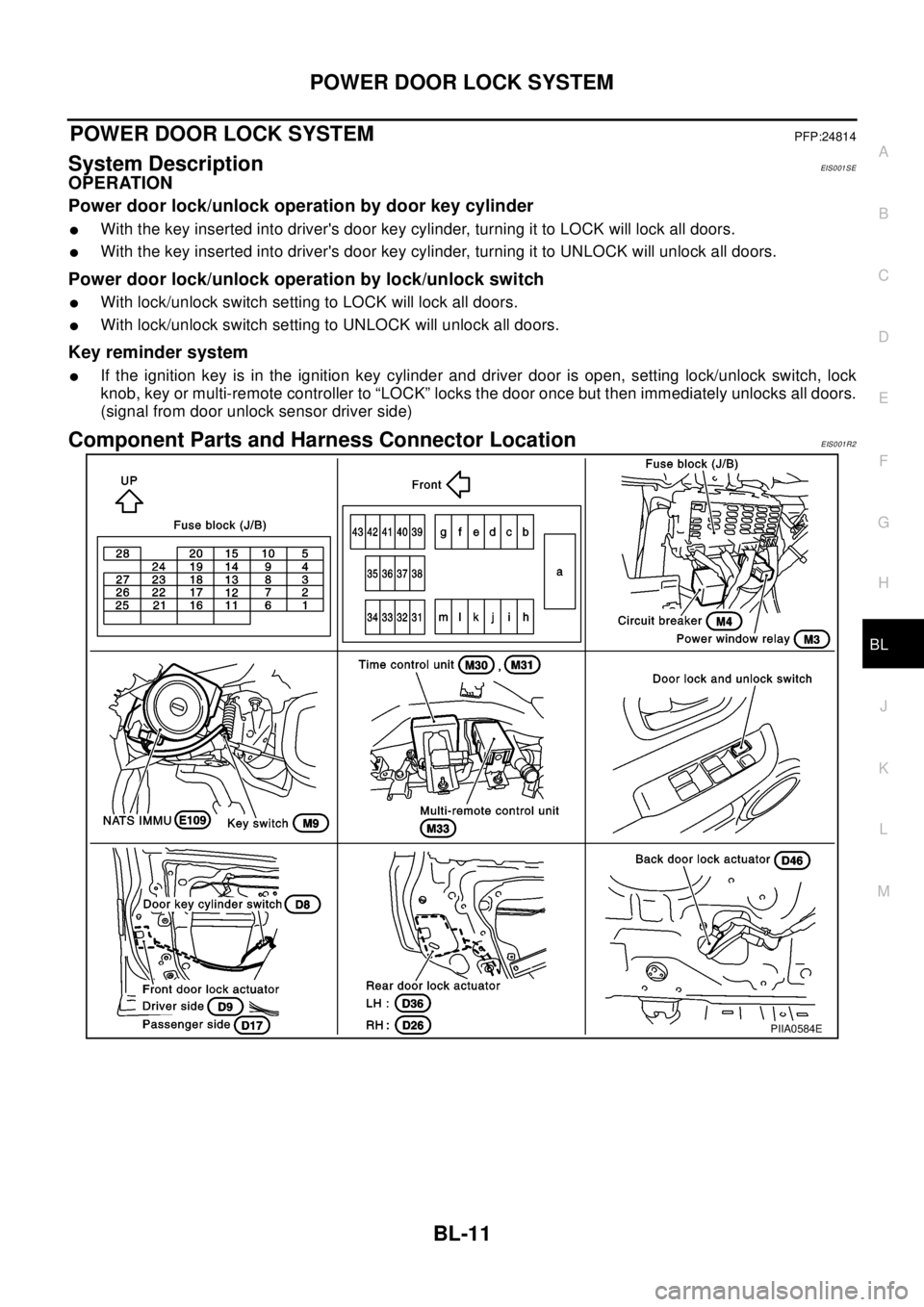
Component Parts and Harness Connector LocationEIS001R2
PIIA0584E
Page 768 of 3066
BL-24
POWER DOOR LOCK — SUPER LOCK —
POWERDOORLOCK—SUPERLOCK—
PFP:24814
System DescriptionEIS0 01 R6
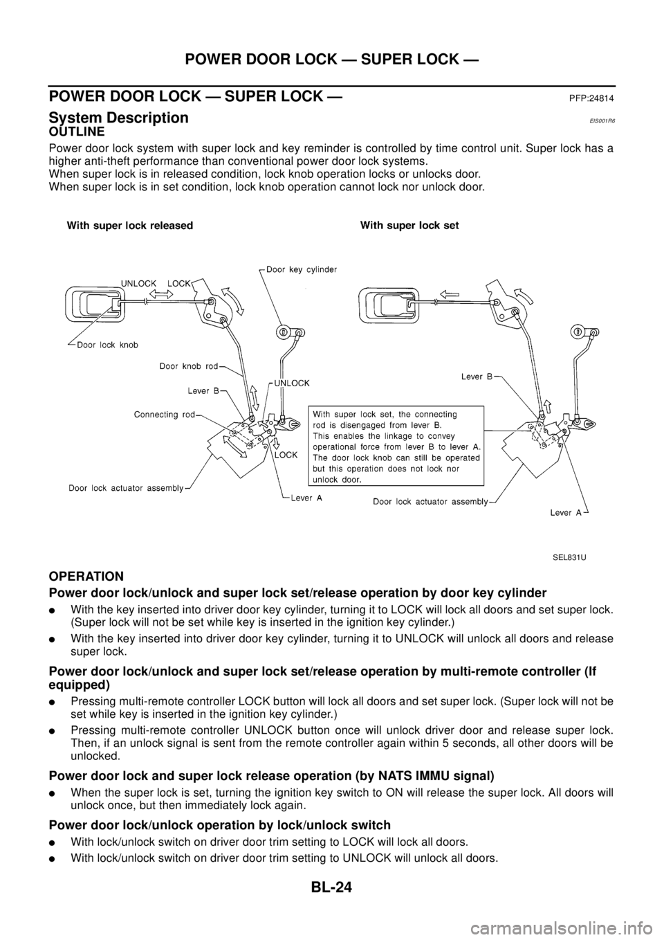
OUTLINE
Power door lock system with super lock and key reminder is controlled by time control unit. Super lock has a
higher anti-theft performance than conventional power door lock systems.
When super lock is in released condition, lock knob operation locks or unlocks door.
When super lock is in set condition, lock knob operation cannot lock nor unlock door.
OPERATION
Power door lock/unlock and super lock set/release operation by door key cylinder
lWith the key inserted into driver door key cylinder, turning it to LOCK will lock all doors and set super lock.
(Super lock will not be set while key is inserted in the ignition key cylinder.)
lWith the key inserted into driver door key cylinder, turning it to UNLOCK will unlock all doors and release
super lock.
Power door lock/unlock and super lock set/release operation by multi-remote controller (If
equipped)
lPressing multi-remote controller LOCK button will lock all doors and set super lock. (Super lock will not be
set while key is inserted in the ignition key cylinder.)
lPressing multi-remote controller UNLOCK button once will unlock driver door and release super lock.
Then, if an unlock signal is sent from the remote controller again within 5 seconds, all other doors will be
unlocked.
Power door lock and super lock release operation (by NATS IMMU signal)
lWhen the super lock is set, turning the ignition key switch to ON will release the super lock. All doors will
unlock once, but then immediately lock again.
Power door lock/unlock operation by lock/unlock switch
lWith lock/unlock switch on driver door trim setting to LOCK will lock all doors.
lWith lock/unlock switch on driver door trim setting to UNLOCK will unlock all doors.
SEL831U
Page 769 of 3066

POWER DOOR LOCK — SUPER LOCK —
BL-25
C
D
E
F
G
H
J
K
L
MA
B
BL
Lock/unlock switch operation cannot control super lock
Key reminder system
lIf the ignition key is in the ignition key cylinder and driver door is open, setting lock/unlock switch, lock
knob, key or multi-remote controller to “LOCK” locks the door once but then immediately unlocks all doors.
(signal from door unlock sensor driver side)
System initialization
lSystem initialization is required when battery cables are reconnected. Conduct the following to release
super lock once;
–insert the key into the ignition key cylinder and turn it to ON.
–LOCK/UNLOCK operation using door key cylinder or multi-remote controller.
Page 777 of 3066

POWER DOOR LOCK — SUPER LOCK —
BL-33
C
D
E
F
G
H
J
K
L
MA
B
BL
Terminal and Reference Value for Time Control UnitEIS001SR
TER-
MINALWIRE
COLORITEM CONDITIONVOLTAGE
(Approximate values)
1 L/B BAT power supply — Battery voltage
3 L/Y Super lock actuator releaseDoor key cylinder switch
Unlock operation (Released)0V®12V
4G/RPassenger door and rear door
(LH/RH) lock actuator unlockPower door lock switch
Unlock operation0V®12V
6 Y/R Super lock actuator setDoor key cylinder switch
Lock operation (Set)0V®12V
10 W Power source (C/B) — Battery voltage
11 L Driver door lock actuator unlockPower door lock switch
Unlock operation0V®12V
14 R/B All door lock actuator lockPower door lock switch
Lock operation0V®12V
16 B Ground — 0V
17 G IGN power supply — Battery voltage
18 W/L Key switchKey inserted (ON)®key removed
from IGN key cylinder (OFF)Battery voltage®0V
20 GYPower door lock switch lock sig-
nalLock operation (ON) 0V
Other than above (OFF) 5V
23 PUPower door lock switch unlock
signalUnlock operation (ON) 0V
Other than above (OFF) 5V
24 LG/R Door key cylinder lock switch OFF (Neutral)®ON (Locked) 5V®0V
25 OR/L Door key cylinder unlock switch OFF (Neutral)®ON (Unlocked) 5V®0V
28 Y/G Driver door lock switch signalUnlock (ON) 0V
Lock (OFF) 5V
29 Y/LPassenger door lock switch sig-
nalUnlock (ON) 0V
Lock (OFF) 5V
30 R Driver door switch Door open (ON)®close (OFF) 0V®Battery voltage
32 OR Key less lock signalRemote controller button
Lock pressed5V®0V (Approx. 0.5 sec-
onds)
33 P/L Key less unlock signalRemote controller button
Unlock pressed5V®0V (Approx. 0.5 sec-
onds)
34 B/Y NATS release signal — 5V
Page 779 of 3066
POWER DOOR LOCK — SUPER LOCK —
BL-35
C
D
E
F
G
H
J
K
L
MA
B
BL
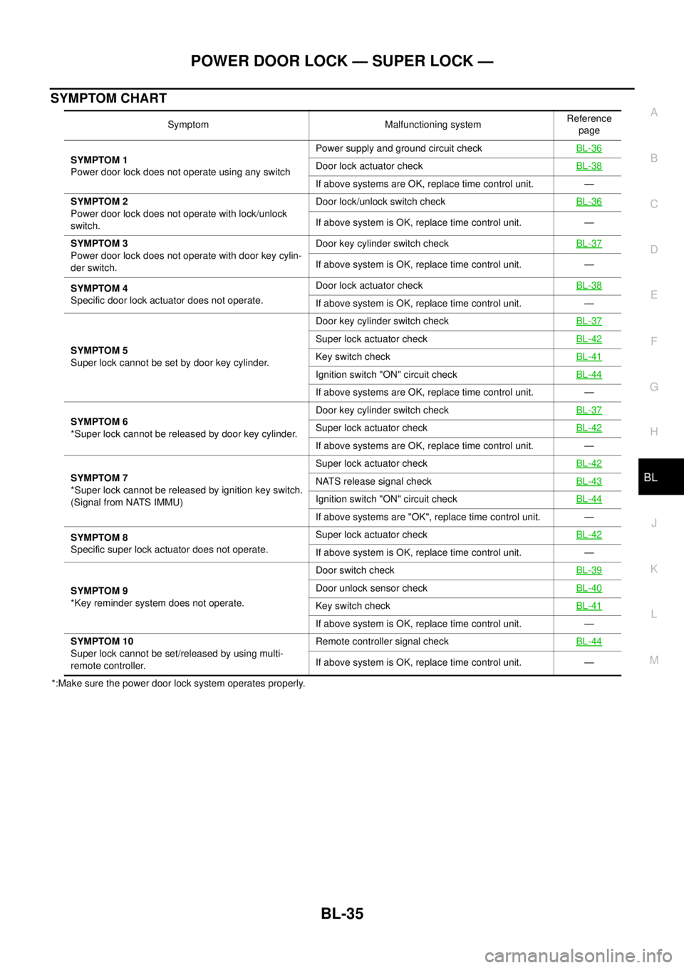
SYMPTOM CHART
*:Make sure the power door lock system operates properly.Symptom Malfunctioning systemReference
page
SYMPTOM 1
Power door lock does not operate using any switchPower supply and ground circuit checkBL-36
Door lock actuator checkBL-38
If above systems are OK, replace time control unit. —
SYMPTOM 2
Power door lock does not operate with lock/unlock
switch.Door lock/unlock switch checkBL-36
If above system is OK, replace time control unit. —
SYMPTOM 3
Power door lock does not operate with door key cylin-
der switch.Door key cylinder switch checkBL-37
If above system is OK, replace time control unit. —
SYMPTOM 4
Specific door lock actuator does not operate.Door lock actuator checkBL-38
If above system is OK, replace time control unit. —
SYMPTOM 5
Super lock cannot be set by door key cylinder.Door key cylinder switch checkBL-37
Super lock actuator checkBL-42
Key switch checkBL-41
Ignition switch "ON" circuit checkBL-44
If above systems are OK, replace time control unit. —
SYMPTOM 6
*Super lock cannot be released by door key cylinder.Door key cylinder switch checkBL-37
Super lock actuator checkBL-42
If above systems are OK, replace time control unit. —
SYMPTOM 7
*Super lock cannot be released by ignition key switch.
(Signal from NATS IMMU)Super lock actuator checkBL-42
NATS release signal checkBL-43
Ignition switch "ON" circuit checkBL-44
If above systems are "OK", replace time control unit. —
SYMPTOM 8
Specific super lock actuator does not operate.Super lock actuator checkBL-42
If above system is OK, replace time control unit. —
SYMPTOM 9
*Key reminder system does not operate.Door switch checkBL-39
Door unlock sensor checkBL-40
Key switch checkBL-41
If above system is OK, replace time control unit. —
SYMPTOM 10
Super lock cannot be set/released by using multi-
remote controller.Remote controller signal checkBL-44
If above system is OK, replace time control unit. —
Page 788 of 3066
BL-44
POWER DOOR LOCK — SUPER LOCK —
Ignition Switch “ON” Circuit Check
EIS001SP
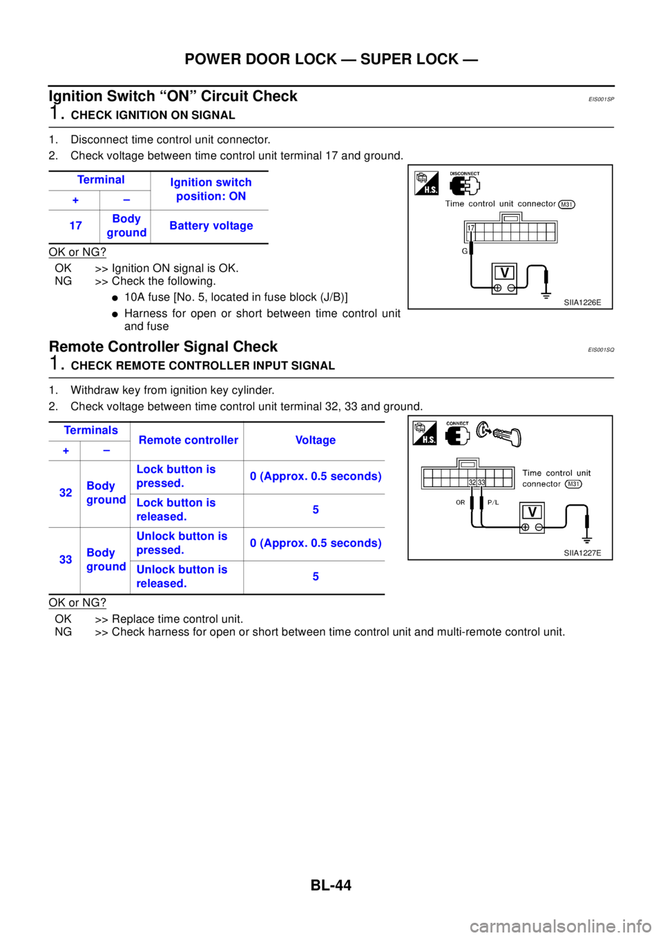
1.CHECK IGNITION ON SIGNAL
1. Disconnect time control unit connector.
2. Check voltage between time control unit terminal 17 and ground.
OK or NG?
OK >> Ignition ON signal is OK.
NG >> Check the following.
l10A fuse [No. 5, located in fuse block (J/B)]
lHarness for open or short between time control unit
and fuse
Remote Controller Signal CheckEIS001SQ
1.CHECK REMOTE CONTROLLER INPUT SIGNAL
1. Withdraw key from ignition key cylinder.
2. Check voltage between time control unit terminal 32, 33 and ground.
OK or NG?
OK >> Replace time control unit.
NG >> Check harness for open or short between time control unit and multi-remote control unit.Te r m i n a l
Ignition switch
position: ON
+–
17Body
groundBattery voltage
SIIA1226E
Te r m i n a l s
Remote controller Voltage
+–
32Body
groundLock button is
pressed.0 (Approx. 0.5 seconds)
Lock button is
released.5
33Body
groundUnlock button is
pressed.0 (Approx. 0.5 seconds)
Unlock button is
released.5
SIIA1227E
Page 789 of 3066
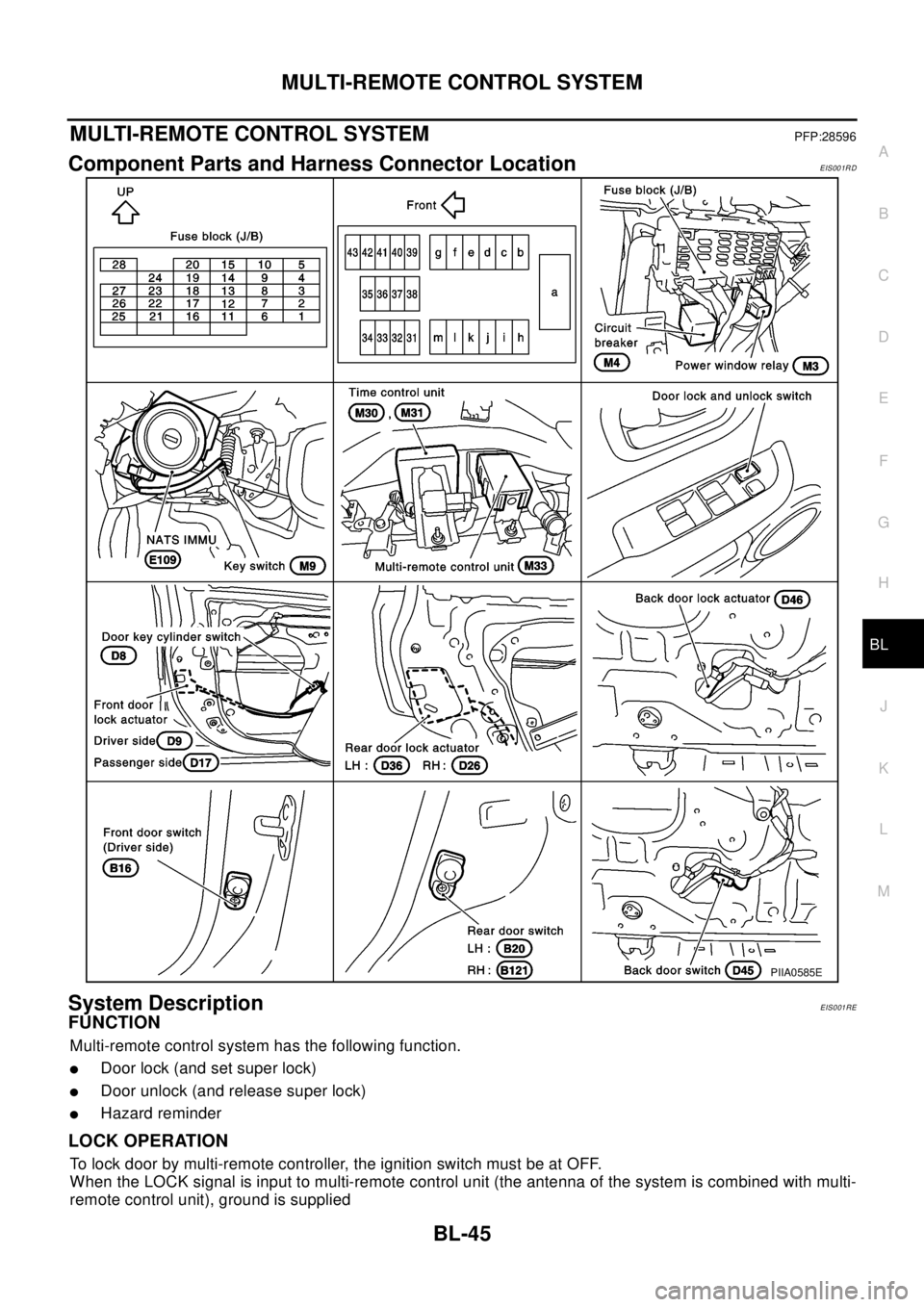
MULTI-REMOTE CONTROL SYSTEM
BL-45
C
D
E
F
G
H
J
K
L
MA
B
BL
MULTI-REMOTE CONTROL SYSTEMPFP:28596
Component Parts and Harness Connector LocationEIS001RD
System DescriptionEIS001RE
FUNCTION
Multi-remote control system has the following function.
lDoor lock (and set super lock)
lDoor unlock (and release super lock)
lHazard reminder
LOCK OPERATION
To lock door by multi-remote controller, the ignition switch must be at OFF.
When the LOCK signal is input to multi-remote control unit (the antenna of the system is combined with multi-
remote control unit), ground is supplied
PIIA0585E
Page 790 of 3066

BL-46
MULTI-REMOTE CONTROL SYSTEM
lthrough multi-remote control unit terminal 5
lto time control unit terminal 32.
Then time control unit operates to lock doors and set super lock (models with super lock).
UNLOCK OPERATION
When the UNLOCK signal is input to multi-remote control unit (the antenna of the system is combined with
multi-remote control unit), ground is supplied
lthrough multi-remote control unit terminal 6
lto time control unit terminal 33.
Time control unit operates to unlock driver's door and release super lock (models with super lock).
Then, if an unlock signal is sent from the remote controller again within 5 seconds, all other doors will be
unlocked.
HAZARD REMINDER
When the doors are locked or unlocked by multi-remote controller (signal from driver side unlock sensor), sup-
ply power to hazard warning lamp flashes as follows
lLock operation: Flash once
lUnlock operation: Flash twice
MULTI-REMOTE CONTROLLER ID CODE ENTRY
A maximum of four remote controllers can be entered.
To enter ID code entry, the following signals must be input to the multi-remote control unit.
lIgnition switch (ON)
lSignal from remote controller
For detailed procedure, refer toBL-52, "
ID Code Entry Procedure".