NOISE, VIBRATION AND HARSHNESS (NVH) TROUBLESHOOTING
BR-5
C
D
E
G
H
I
J
K
L
MA
B
BR
NOISE, VIBRATION AND HARSHNESS (NVH) TROUBLESHOOTINGPFP:00003
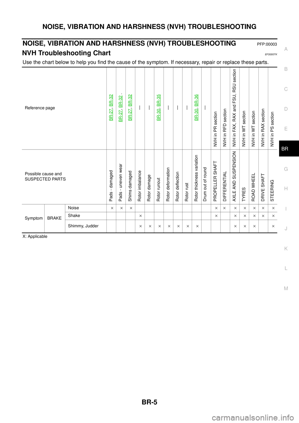
NVH Troubleshooting ChartEFS000TK
Use the chart below to help you find the cause of the symptom. If necessary, repair or replace these parts.
X: ApplicableReference page
BR-27
, BR-32
BR-27
, BR-32
.
BR-27
, BR-32—
—
BR-30, BR-35—
—
—
BR-30, BR-36—
NVH in PR section
NVH in RFD section
NVH in FAX, RAX and FSU, RSU section
NVH in WT section
NVH in WT section
NVH in RAX section
NVH in PS section
Possible cause and
SUSPECTED PARTS
Pads - damaged
Pads - uneven wear
Shims damaged
Rotor imbalance
Rotor damage
Rotor runout
Rotor deformation
Rotor deflection
Rotor rust
Rotor thickness variation
Drum out of round
PROPELLER SHAFT
DIFFERENTIAL
AXLE AND SUSPENSION
TYRES
ROAD WHEEL
DRIVE SHAFT
STEERING
Symptom BRAKENoise××× ×× ×××
××
Shake×××××
××
Shimmy, Judder××××××× ××× ×
BR-36
REAR DISC BRAKE
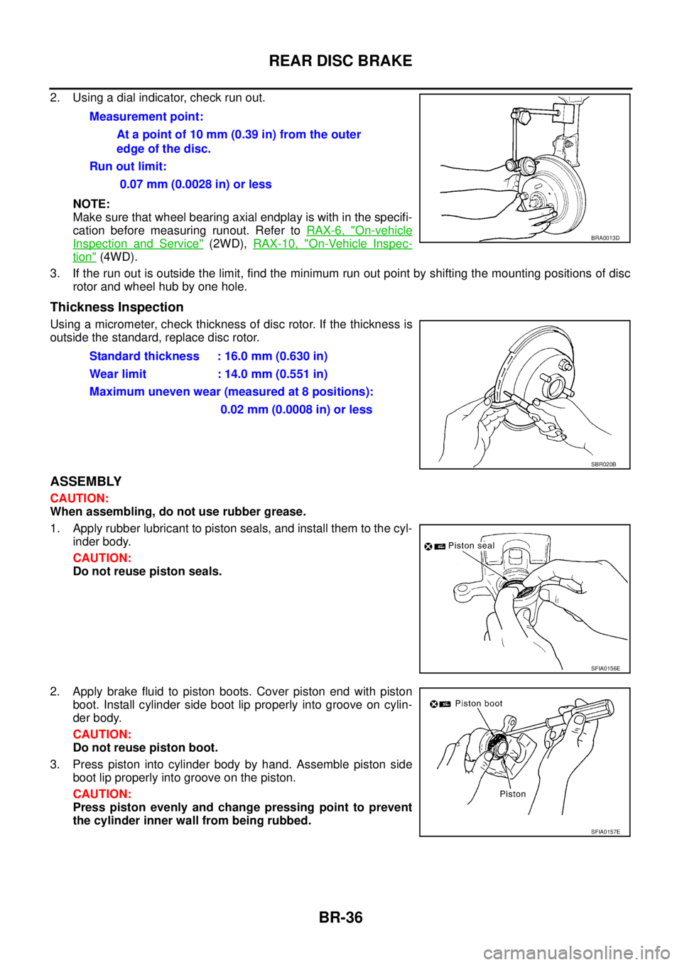
2. Using a dial indicator, check run out.
NOTE:
Make sure that wheel bearing axial endplay is with in the specifi-
cation before measuring runout. Refer to RAX-6, "
On-vehicle
Inspection and Service" (2WD), RAX-10, "On-Vehicle Inspec-
tion" (4WD).
3. If the run out is outside the limit, find the minimum run out point by shifting the mounting positions of disc
rotor and wheel hub by one hole.
Thickness Inspection
Using a micrometer, check thickness of disc rotor. If the thickness is
outside the standard, replace disc rotor.
ASSEMBLY
CAUTION:
When assembling, do not use rubber grease.
1. Apply rubber lubricant to piston seals, and install them to the cyl-
inder body.
CAUTION:
Do not reuse piston seals.
2. Apply brake fluid to piston boots. Cover piston end with piston
boot. Install cylinder side boot lip properly into groove on cylin-
der body.
CAUTION:
Do not reuse piston boot.
3. Press piston into cylinder body by hand. Assemble piston side
boot lip properly into groove on the piston.
CAUTION:
Press piston evenly and change pressing point to prevent
the cylinder inner wall from being rubbed.Measurement point:
At a point of 10 mm (0.39 in) from the outer
edge of the disc.
Run out limit:
0.07 mm (0.0028 in) or less
BRA0013D
Standard thickness : 16.0 mm (0.630 in)
Wear limit : 14.0 mm (0.551 in)
Maximum uneven wear (measured at 8 positions):
0.02 mm (0.0008 in) or less
SBR020B
SFIA0156E
SFIA0157E