engine NISSAN XTERRA 2002 WD22 / 1.G User Guide
[x] Cancel search | Manufacturer: NISSAN, Model Year: 2002, Model line: XTERRA, Model: NISSAN XTERRA 2002 WD22 / 1.GPages: 263, PDF Size: 2.22 MB
Page 61 of 263
High beam indicator light
This blue light comes on when the headlight
high beams are on and goes out when the
low beams are selected.
The high beam indicator light also comes on
when the passing signal is activated.
Malfunction indicator light
(MIL)
If this indicator light comes on steady or
blinks while the engine is running, it may
indicate a potential emission control mal-
function.
The malfunction indicator lamp may also
come on steady if the fuel filler cap is loose
or missing, or if the vehicle runs out of fuel.
Check to make sure the fuel filler cap is
installed and closed tightly, and that the
vehicle has at least three gallons of fuel in
the fuel tank.
After a few driving trips, the
lamp
should turn off if no other potential emission
control system malfunction exists.
Operation
The malfunction indicator lamp will come on
in one of two ways:O
Malfunction indicator lamp on steady þ An
emission control system malfunction has
been detected. Check the fuel filler cap. If
the fuel filler cap is loose or missing, tighten
or install the cap and continue to drive the
vehicle. The
lamp should turn off
after a few driving trips. If the
lamp
does not turn off after a few driving trips,
have the vehicle inspected by an autho-
rized NISSAN dealer. You do not need to
have your vehicle towed to the dealer.
OMalfunction indicator lamp blinking þ An
engine misfire has been detected which
may damage the emission control sys-
tem. To reduce or avoid emission control
system damage:
Odo not drive at speeds above 45 MPH
(72 km/h).
O
avoid hard acceleration or deceleration.
Oavoid steep uphill grades.
Oif possible, reduce the amount of cargo
being hauled or towed.
The malfunction indicator lamp may stop
blinking and come on steady.
Have the vehicle inspected by an autho-
rized NISSAN dealer. You do not need to
have your vehicle towed to the dealer.
CAUTION
Continued vehicle operation without
having the emission control system
checked and repaired as necessary
could lead to poor driveability, reduced
fuel economy, and possible damage to
the emission control system.
Overdrive off indicator light
(automatic transmission mod-
els only)
This light comes on when the overdrive
switch is pushed to the OFF position.
Turn signal/hazard indicator
lights
These lights flash when the turn signal
switch or hazard switch is turned on.
AUDIBLE REMINDERS
Brake pad wear warning
The disc brake pads have audible wear
warnings. When a brake pad requires re-
placement, it makes a high pitched scraping
sound when the vehicle is in motion whether
or not the brake pedal is depressed. Have
2-14Instruments and controls
ZX
Page 67 of 263
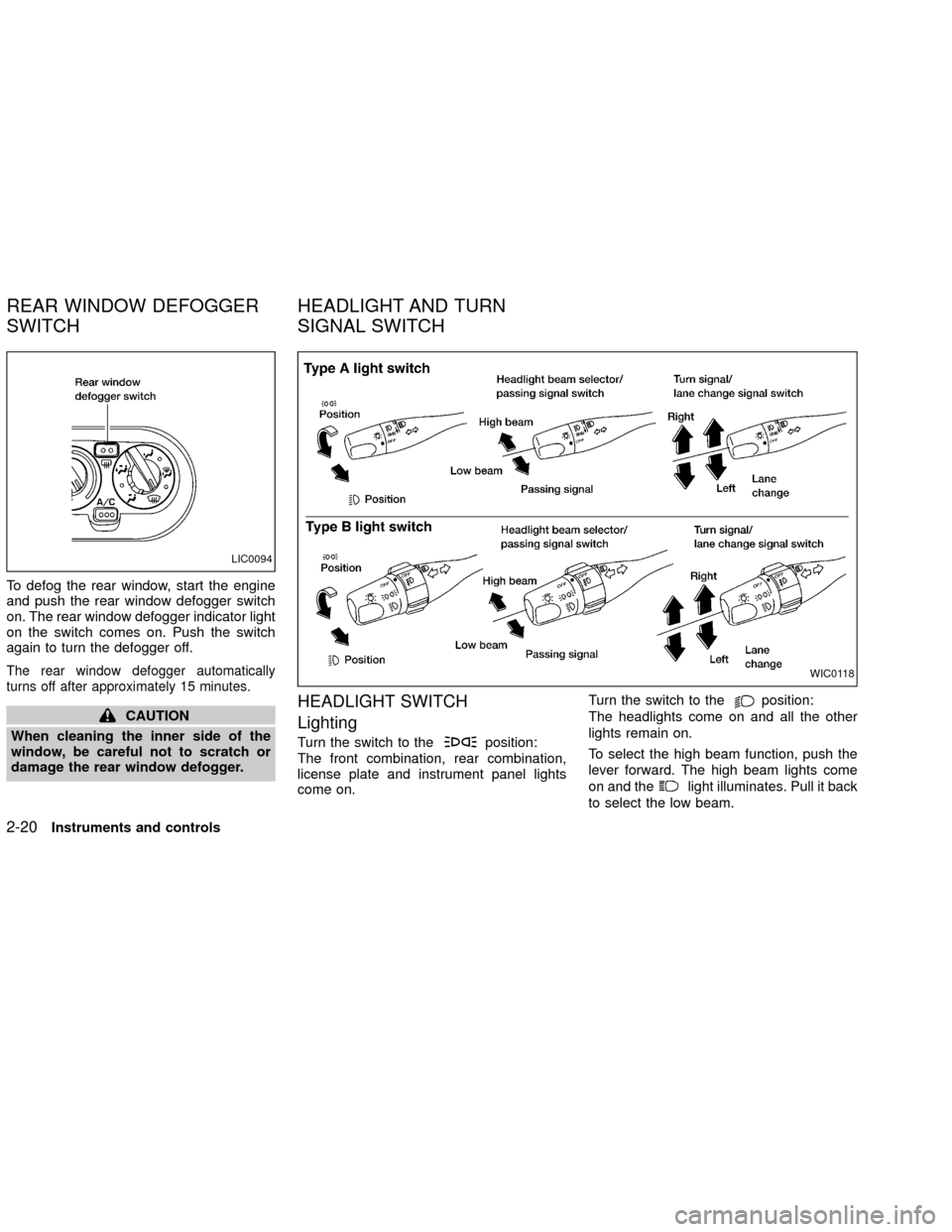
To defog the rear window, start the engine
and push the rear window defogger switch
on. The rear window defogger indicator light
on the switch comes on. Push the switch
again to turn the defogger off.
The rear window defogger automatically
turns off after approximately 15 minutes.
CAUTION
When cleaning the inner side of the
window, be careful not to scratch or
damage the rear window defogger.HEADLIGHT SWITCH
Lighting
Turn the switch to theposition:
The front combination, rear combination,
license plate and instrument panel lights
come on.Turn the switch to the
position:
The headlights come on and all the other
lights remain on.
To select the high beam function, push the
lever forward. The high beam lights come
on and the
light illuminates. Pull it back
to select the low beam.
LIC0094
WIC0118
REAR WINDOW DEFOGGER
SWITCHHEADLIGHT AND TURN
SIGNAL SWITCH
2-20Instruments and controls
ZX
Page 68 of 263
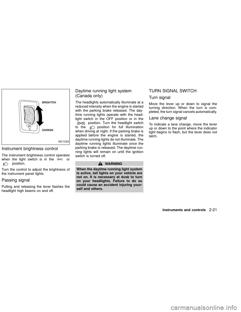
Instrument brightness control
The instrument brightness control operates
when the light switch is in the
or
position.
Turn the control to adjust the brightness of
the instrument panel lights.
Passing signal
Pulling and releasing the lever flashes the
headlight high beams on and off.
Daytime running light system
(Canada only)
The headlights automatically illuminate at a
reduced intensity when the engine is started
with the parking brake released. The day-
time running lights operate with the head-
light switch in the OFF position or in the
position. Turn the headlight switch
to the
position for full illumination
when driving at night. If the parking brake is
applied before the engine is started, the
daytime running lights do not illuminate. The
daytime running lights illuminate once the
parking brake is released. The daytime run-
ning lights will remain on until the ignition
switch is turned off.
WARNING
When the daytime running light system
is active, tail lights on your vehicle are
not on. It is necessary at dusk to turn
on your headlights. Failure to do so
could cause an accident injuring your-
self and others.
TURN SIGNAL SWITCH
Turn signal
Move the lever up or down to signal the
turning direction. When the turn is com-
pleted, the turn signal cancels automatically.
Lane change signal
To indicate a lane change, move the lever
up or down to the point where the indicator
light begins to flash, but the lever does not
latch.
AIC1023
Instruments and controls2-21
ZX
Page 71 of 263
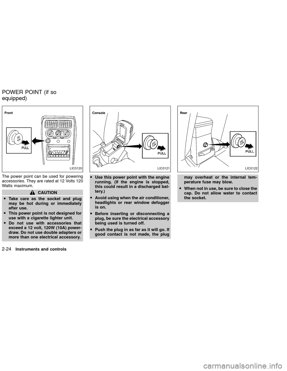
The power point can be used for powering
accessories. They are rated at 12 Volts 120
Watts maximum.
CAUTION
OTake care as the socket and plug
may be hot during or immediately
after use.
OThis power point is not designed for
use with a cigarette lighter unit.
ODo not use with accessories that
exceed a 12 volt, 120W (10A) power-
draw. Do not use double adapters or
more than one electrical accessory.OUse this power point with the engine
running. (If the engine is stopped,
this could result in a discharged bat-
tery.)
OAvoid using when the air conditioner,
headlights or rear window defogger
is on.
OBefore inserting or disconnecting a
plug, be sure the electrical accessory
being used is turned off.
OPush the plug in as far as it will go. If
good contact is not made, the plugmay overheat or the internal tem-
perature fuse may blow.
OWhen not in use, be sure to close the
cap. Do not allow water to contact
the socket.
LIC0120LIC0121LIC0122
POWER POINT (if so
equipped)
2-24Instruments and controls
ZX
Page 81 of 263
For information regarding dome light bulb
replacement, refer to ªBulb replacementº in
the ``Maintenance and do-it-yourself'' sec-
tion of this manual.
CAUTION
Leaving the dome light switch in the ON
position for extended periods of time
will result in a discharged battery.
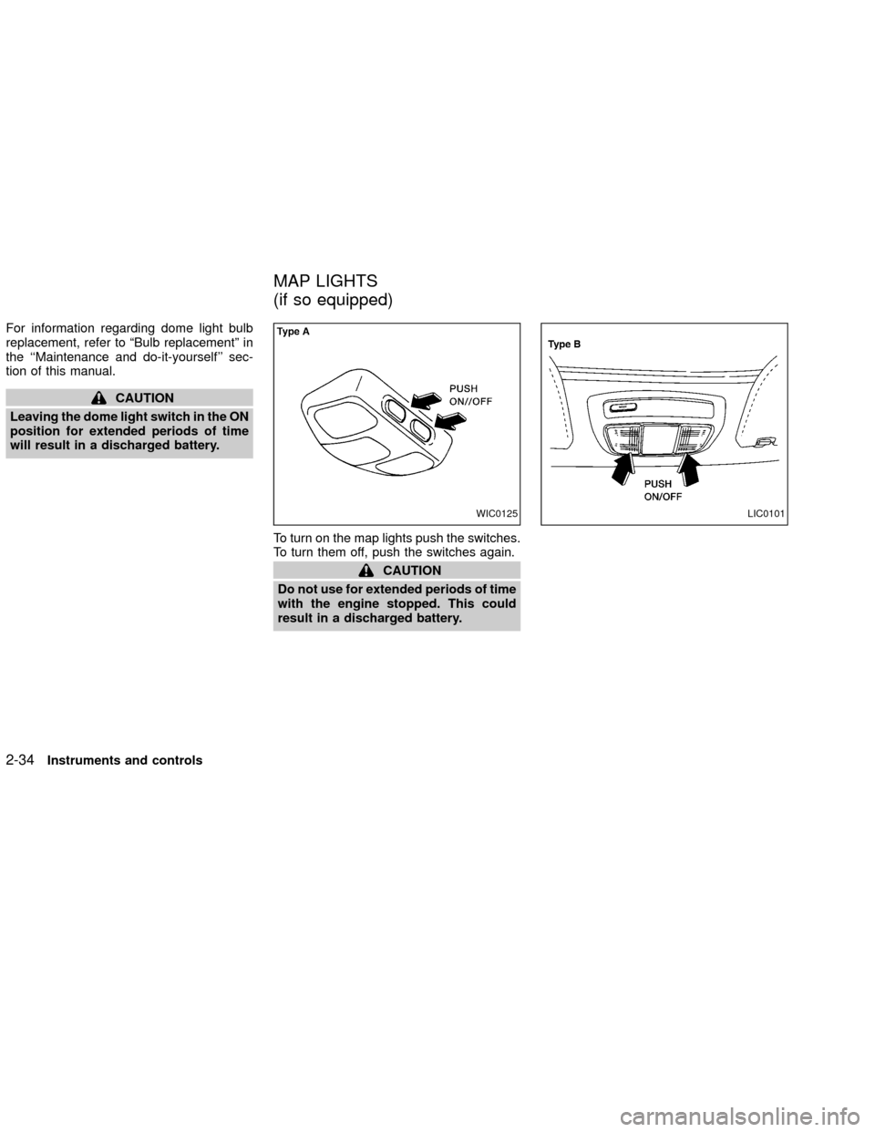
To turn on the map lights push the switches.
To turn them off, push the switches again.
CAUTION
Do not use for extended periods of time
with the engine stopped. This could
result in a discharged battery.
WIC0125LIC0101
MAP LIGHTS
(if so equipped)
2-34Instruments and controls
ZX
Page 91 of 263

device must accept any interference re-
ceived including interference that may
cause undesired operation of the device.
WARNING
OMake sure the hood is completely
closed and latched before driving.
Failure to do so could cause the
hood to fly open and result in an
accident.
OIf you see steam or smoke coming
from the engine compartment, to
avoid injury do not open the hood.
1. Pull the hood lock release handle located
below the driver side instrument panel;
the hood then springs up slightly.2. Lift the lever at the front of the hood with
your fingertips and raise the hood.
3. Insert the support rod into the slot in the
front edge of the hood.
4. When closing the hood, reset the support
rod to its original position, lower the hood
to approximately 12 inches (30.5 cm)
above the latch and release it. This al-
lows proper engagement of the hood
latch.
LPD0061
HOOD
3-8Pre-driving checks and adjustments
ZX
Page 96 of 263
FUEL FILLER CAP
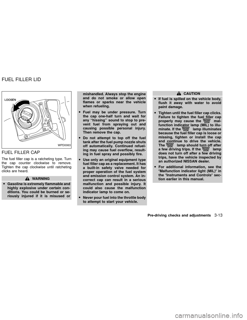
The fuel filler cap is a ratcheting type. Turn
the cap counter clockwise to remove.
Tighten the cap clockwise until ratcheting
clicks are heard.
WARNING
OGasoline is extremely flammable and
highly explosive under certain con-
ditions. You could be burned or se-
riously injured if it is misused ormishandled. Always stop the engine
and do not smoke or allow open
flames or sparks near the vehicle
when refueling.
OFuel may be under pressure. Turn
the cap one-half turn and wait for
any ``hissing'' sound to stop to pre-
vent fuel from spraying out and
causing possible personal injury.
Then remove the cap.
ODo not attempt to top off the fuel
tank after the fuel pump nozzle shuts
off automatically. Continued refuel-
ing may cause fuel overflow, result-
ing in fuel spray and possibly fire.
OUse only an original equipment type
fuel filler cap as a replacement. It has
a built-in safety valve needed for
proper operation of the fuel system
and emission control system. An in-
correct cap can result in a serious
malfunction and possible injury. It
could also cause the malfunction
indicator lamp to come on.
ONever pour fuel into the throttle body
to attempt to start your vehicle.
CAUTION
OIf fuel is spilled on the vehicle body,
flush it away with water to avoid
paint damage.
OTighten until the fuel filler cap clicks.
Failure to tighten the fuel filler cap
properly may cause the
mal-
function indicator lamp (MIL) to illu-
minate. If the
lamp illuminates
because the fuel filler cap is loose or
missing, tighten or install the cap
and continue to drive the vehicle.
The
lamp should turn off after
a few driving trips. If thelamp
does not turn off after a few driving
trips, have the vehicle inspected by
an authorized NISSAN dealer.
OFor additional information, see the
(Malfunction indicator light (MIL)(in
the(Instruments and Controls(sec-
tion earlier in this manual.
WPD0063
FUEL FILLER LID
Pre-driving checks and adjustments3-13
ZX
Page 102 of 263
WARNING
OThe air conditioner cooling function
operates only when the engine is
running.
ODo not leave children, unreliable
adults, or pets alone in your vehicle.
On hot sunny days, temperatures in
a closed vehicle could quickly be-
come high enough to cause severe
or possibly fatal injuries to people or
animals.
ODo not use the recirculation mode
for long periods as it may cause theinterior air to become stale and the
windows to fog up.
OPositioning of the heater or air con-
ditioner controls should not be done
while driving so full attention may be
given to vehicle operation.
CONTROLS
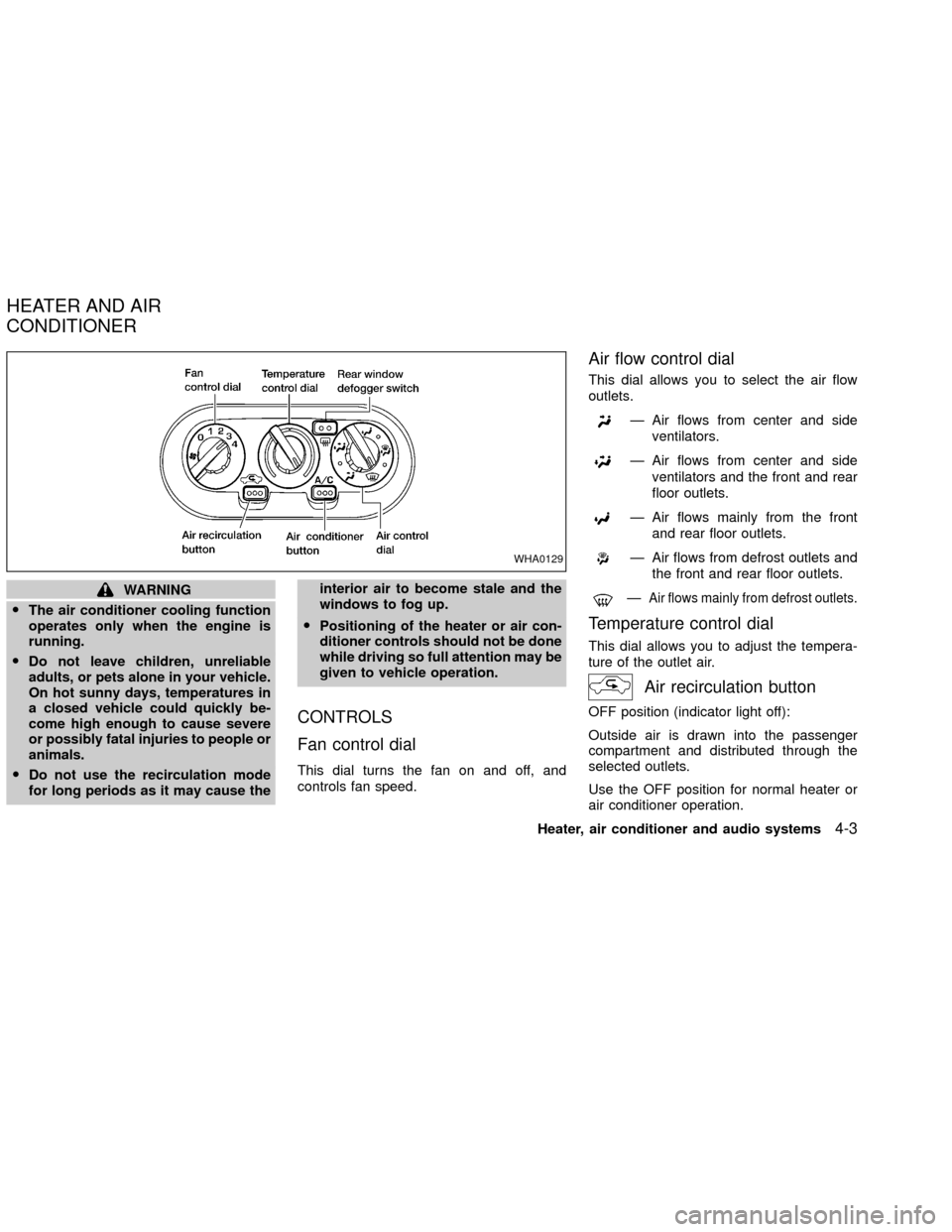
Fan control dial
This dial turns the fan on and off, and
controls fan speed.
Air flow control dial
This dial allows you to select the air flow
outlets.
Ð Air flows from center and side
ventilators.
Ð Air flows from center and side
ventilators and the front and rear
floor outlets.
Ð Air flows mainly from the front
and rear floor outlets.
Ð Air flows from defrost outlets and
the front and rear floor outlets.
ÐAir flows mainly from defrost outlets.
Temperature control dial
This dial allows you to adjust the tempera-
ture of the outlet air.
Air recirculation button
OFF position (indicator light off):
Outside air is drawn into the passenger
compartment and distributed through the
selected outlets.
Use the OFF position for normal heater or
air conditioner operation.
WHA0129
HEATER AND AIR
CONDITIONER
Heater, air conditioner and audio systems4-3
ZX
Page 103 of 263

ON position (indicator light on):
Interior air is recirculated inside the vehicle.
Push the
button to the on position
when:
Odriving on a dusty road.
Oto prevent traffic fumes from entering the
passenger compartment.
Ofor maximum cooling when using the air
conditioner.
Air conditioner button
Start the engine, move the fan control dial to
the desired (one to four) position, and push
the air conditioner button to turn on the air
conditioner. The indicator light comes on
when the air conditioner is operating. To turn
off the air conditioner, push the button
again.
The air conditioner cooling function op-
erates only when the engine is running.
HEATER OPERATION
Heating
This mode is used to direct most of the hot
air to the front and rear floor outlets. Rearpassenger heat is provided by the front
system through floor outlets located under
both front seats. A small amount of air also
flows from the defrost outlets.
1. Push the
button to the off position
for normal heating.
2. Turn the air control dial to the
posi-
tion.
3. Turn the fan control dial to the desired
position.
4. Turn the temperature control dial to the
desired position between the middle and
the hot position.
Ventilation
This mode directs outside air from the side
and center vents.
1. Push the
button to the off position.
2. Turn the air control dial to the
posi-
tion.
3. Turn the fan control dial to the desired
position.
4. Turn the temperature control dial to the
desired position.
Defrosting or defogging
This mode directs the air to the defrost
outlets to defrost/defog the windows.
1. Turn the air control dial to the
posi-
tion.
2. Turn the fan control dial to the desired
position.
3. Turn the temperature control dial to the
desired position.
When the
position is selected, the air
conditioner automatically turns on (however
the indicator light will not illuminate) if the
outside temperature is more than
45ÉF(7ÉC). This dehumidifies the air which
helps defog the windshield. The
mode automatically turns off, allow-
ing outside air to be drawn into the passen-
ger compartment to further improve the
defogging performance.
Bi-level heating
The bi-level mode directs warmed air to the
side and center vents and to the front and
rear floor outlets.
1. Push the
button to the off position.
4-4Heater, air conditioner and audio systems
ZX
Page 104 of 263

2. Turn the air control dial to theposi-
tion.
3. Turn the fan control dial to the desired
position.
4. Turn the temperature control dial to the
the desired position.
Heating and defogging
This mode directs a portion of the air to the
defrost outlets to defrost/defog the win-
dows, and also directs air to the front and
rear floor outlets to heat the cabin.
1. Turn the air control dial to the
posi-
tion.
2. Turn the fan control dial to the desired
position.
3. Turn the temperature control dial to the
desired position between the middle and
the hot position.
When the
position is selected, the air
conditioner automatically turns on (however
the indicator light will not illuminate) if the
outside temperature is more than 45ÉF
(7ÉC). This dehumidifies the air which helps
defog the windshield. The
mode auto-
maticallly turns off, allowing outside air to bedrawn into the passenger compartment to
further improve the defogging performance.
Operating tips
Clear snow and ice from the wiper
blades and air inlet in front of the wind-
shield. This improves heater operation.
AIR CONDITIONER OPERATION
Start the engine, move the fan control dial to
the desired (one to four) position, and push
in the air conditioner button to activate the
air conditioner. When the air conditioner is
on, cooling and dehumidifying functions are
added to the heater operation.
The air conditioner cooling function op-
erates only when the engine is running.
Cooling
This mode directs cooled and dryed air to
the side and center vents to cool and dehu-
midify the cabin.
1. Push the
button to the off position.
2. Turn the air control dial to the
posi-
tion.
3. Turn the fan control dial to the desired
position.4. Push on the air conditioner button. The
indicator light comes on.
5. Turn the temperature control dial to the
desired position.
For quick cooling when the outside tem-
perature is high, push the
button to
the ON position. Be sure to return the air
recirculation button to the OFF position for
normal cooling.
Dehumidified heating
This mode directs warmed and dryed air to
the front and rear floor outlets to heat and
dehumidify the cabin.
1. Push the
button to the off position.
2. Turn the air control dial to the
posi-
tion.
3. Turn the fan control dial to the desired
position.
4. Push on the air conditioner button. The
indicator light comes on.
5. Turn the temperature control dial to the
desired position.
Dehumidified defogging
This mode directs warmed and dryed air to
Heater, air conditioner and audio systems
4-5
ZX