climate control Oldsmobile Alero 2002 Owner's Manuals
[x] Cancel search | Manufacturer: OLDSMOBILE, Model Year: 2002, Model line: Alero, Model: Oldsmobile Alero 2002Pages: 343, PDF Size: 2.41 MB
Page 99 of 343

2-37
Running Your Engine While You're
Parked (Automatic Transaxle)
It's better not to park with the engine running. But if you
ever have to, here are some things to know.
CAUTION:
Idling the engine with the climate control
system off could allow dangerous exhaust into
your vehicle. See the earlier Caution under
ªEngine Exhaust.º
Also, idling in a closed-in place can let deadly
carbon monoxide (CO) into your vehicle even
if the fan is at the highest setting. One place
this can happen is a garage. Exhaust
-- with
CO
-- can come in easily. NEVER park in a
garage with the engine running.
Another closed-in place can be a blizzard.
See ªBlizzardº in the Index.
CAUTION:
It can be dangerous to get out of your vehicle if
the shift lever is not fully in PARK (P) with the
parking brake firmly set. Your vehicle can roll.
Don't leave your vehicle when the engine is
running unless you have to. If you've left the
engine running, the vehicle can move suddenly.
You or others could be injured. To be sure your
vehicle won't move, even when you're on fairly
level ground, always set your parking brake and
move the shift lever to PARK (P).
Follow the proper steps to be sure your vehicle won't
move. See ªShifting Into PARK (P)º in the Index.
If you are parking on a hill and if you're pulling a
trailer, also see ªTowing a Trailerº in the Index.
Horn
You can sound the horn by pressing the horn symbol
on your steering wheel.
Page 119 of 343

2-57
The main components of your instrument panel are the following:
A. Instrument Panel Fuse Blocks
B. Vents
C. Instrument Panel Cluster
D. Hazard Warning Flasher Button
E. Audio System
F. Climate Control System
G. Side Window Defogger Vent
H. Fog Lamp Button (If Equipped)
I. Instrument Panel Brightness Thumbwheel
J. Turn Signal/Multifunction LeverK. Hood Release Handle
L. Cruise Control Switches
M. Tilt Wheel Lever
N. Ignition Switch
O. Windshield Wiper/Washer Lever
P. Enhanced Traction System Button
Q. Transaxle Shift Lever
R. Parking Brake
S. Cigarette Lighter/Accessory Power Outlet
T. Accessory Power Outlet
Page 138 of 343

3-
3-1
Section 3 Comfort Controls and Audio Systems
In this section, you'll find out how to operate the comfort control and audio systems offered with your vehicle. Be
sure to read about the particular systems supplied with your vehicle.
3
-2 Comfort Controls
3
-2 Climate Control System with
Air Conditioning
3
-3 Air Conditioning
3
-4 Heating
3
-4 Defogging and Defrosting Windows
3
-5 Rear Window Defogger
3
-5 Ventilation System
3
-7 Audio Systems
3
-7 Setting the Clock
3
-7AM-FM Stereo with Compact Disc Player
with Programmable Equalization and Radio
Data System (RDS)3
-15 AM-FM Stereo with Cassette Tape and
Compact Disc Player with Programmable
Equalization and Radio Data System (RDS)
(If Equipped)
3
-24 Theft-Deterrent Feature
3
-24 Understanding Radio Reception
3
-25 Tips About Your Audio System
3
-26 Care of Your Cassette Tape Player
3
-27 Care of Your Compact Discs
3
-27 Care of Your Compact Disc Player
3
-28 Backglass Antenna
3
-28 Chime Level Adjustment
Page 139 of 343

3-2
Comfort Controls
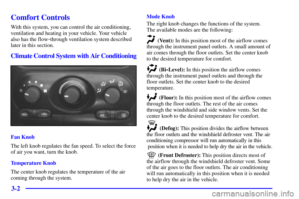
With this system, you can control the air conditioning,
ventilation and heating in your vehicle. Your vehicle
also has the flow
-through ventilation system described
later in this section.
Climate Control System with Air Conditioning
Fan Knob
The left knob regulates the fan speed. To select the force
of air you want, turn the knob.
Temperature Knob
The center knob regulates the temperature of the air
coming through the system.Mode Knob
The right knob changes the functions of the system.
The available modes are the following:
(Vent): In this position most of the airflow comes
through the instrument panel outlets. A small amount of
air comes through the floor outlets. Set the center knob
to the desired temperature for comfort.
(Bi-Level): In this position the airflow comes
through the instrument panel outlets and through the
floor outlets. Set the center knob to the desired
temperature.
(Floor): In this position most of the airflow comes
through the floor outlets. The rest of the air comes
through the windshield and side window vents. Set the
center knob to the desired temperature for comfort.
(Defog): This position divides the airflow between
the floor outlets and the windshield defroster vent. The air
conditioning compressor will run automatically in this
position when it is needed to help dry the air in the vehicle.
(Front Defroster): This position directs most of
the airflow through the windshield defroster vent. Some
of the air goes to the floor outlets. The air conditioning
will run automatically in this position when it is needed
to help dry the air in the vehicle.
Page 142 of 343

3-5 Rear Window Defogger
The rear window defogger uses a warming grid to
remove fog from the rear window.
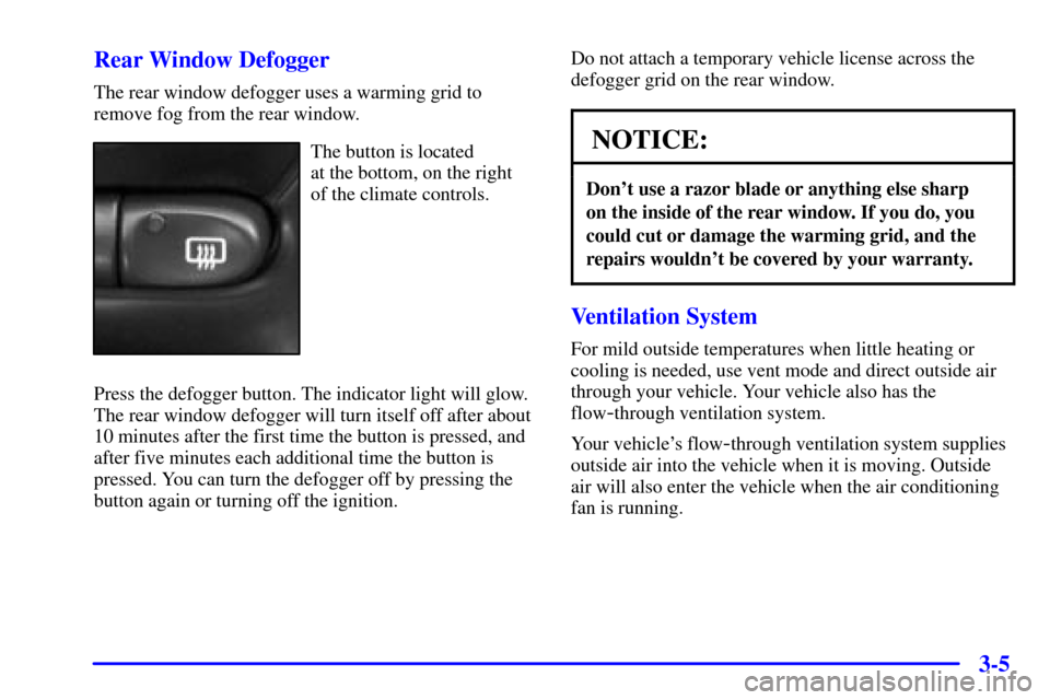
The button is located
at the bottom, on the right
of the climate controls.
Press the defogger button. The indicator light will glow.
The rear window defogger will turn itself off after about
10 minutes after the first time the button is pressed, and
after five minutes each additional time the button is
pressed. You can turn the defogger off by pressing the
button again or turning off the ignition.Do not attach a temporary vehicle license across the
defogger grid on the rear window.NOTICE:
Don't use a razor blade or anything else sharp
on the inside of the rear window. If you do, you
could cut or damage the warming grid, and the
repairs wouldn't be covered by your warranty.
Ventilation System
For mild outside temperatures when little heating or
cooling is needed, use vent mode and direct outside air
through your vehicle. Your vehicle also has the
flow
-through ventilation system.
Your vehicle's flow
-through ventilation system supplies
outside air into the vehicle when it is moving. Outside
air will also enter the vehicle when the air conditioning
fan is running.
Page 284 of 343

6-47 Uniform Tire Quality Grading
Quality grades can be found where applicable on the tire
sidewall between tread shoulder and maximum section
width. For example:
Treadwear 200 Traction AA Temperature A
The following information relates to the system
developed by the United States National Highway
Traffic Safety Administration, which grades tires by
treadwear, traction and temperature performance. (This
applies only to vehicles sold in the United States.) The
grades are molded on the sidewalls of most passenger
car tires. The Uniform Tire Quality Grading system does
not apply to deep tread, winter
-type snow tires,
space
-saver or temporary use spare tires, tires with
nominal rim diameters of 10 to 12 inches (25 to 30 cm),
or to some limited
-production tires.
While the tires available on General Motors passenger
cars and light trucks may vary with respect to these
grades, they must also conform to federal safety
requirements and additional General Motors Tire
Performance Criteria (TPC) standards.Treadwear
The treadwear grade is a comparative rating based on
the wear rate of the tire when tested under controlled
conditions on a specified government test course.
For example, a tire graded 150 would wear one and a
half (1 1/2) times as well on the government course
as a tire graded 100. The relative performance of tires
depends upon the actual conditions of their use,
however, and may depart significantly from the norm
due to variations in driving habits, service practices and
differences in road characteristics and climate.
Traction
-- AA, A, B, C
The traction grades, from highest to lowest, are AA, A,
B, and C. Those grades represent the tire's ability to stop
on wet pavement as measured under controlled
conditions on specified government test surfaces of
asphalt and concrete. A tire marked C may have poor
traction performance. Warning: The traction grade
assigned to this tire is based on straight
-ahead braking
traction tests, and does not include acceleration,
cornering, hydroplaning, or peak traction characteristics.
Page 301 of 343

6-64
Engine Compartment Fuse Block
The engine compartment fuse block is located
on the driver's side of the engine compartment, near
the battery.Maxifuses Usage
1 Ignition Switch
2 Right Electrical Center
-Fog
Lamps, Radio, Body Function
Control Module, Interior Lamps
3 Left Electrical Center
-Stop
Lamps, Hazard Lamps, Body
Function Control Module, Cluster,
Climate Control System
4 Anti
-Lock Brakes
5 Ignition Switch
6 Not Used
7 Left Electrical Center
-Power
Seats, Power Mirrors, Door Locks,
Trunk Release, Audio Amplifier,
Remote Keyless Entry
8 Cooling Fan #1
Page 302 of 343

6-65
Mini Relays Usage
9 Rear Defog
10 Not Used
11 Not Used
12 Cooling Fan #1
13 HVAC Blower (Climate Control)
14 Cooling Fan #2
15 Cooling Fan
Micro Relays Usage
16 Air Conditioning Compressor
17 Not Used
18 Fuel Pump
19 Automatic Light Control
20 Automatic Light Control
21 Horn
22 Daytime Running Lamps (DRL)Minifuses Usage
23
- 32 Spare Fuse Holder
33 Rear Defog
34 Accessory Power Outlets,
Cigarette Lighter
35 Not Used
36 Not Used
37 Air Conditioning Compressor,
Body Function Control Module
38 Automatic Transaxle
39 Powertrain Control
Module (PCM)
40 Anti
-Lock Brakes (ABS), Variable
Effort Steering
41 Ignition System
42 Back
-Up Lamps, Brake Transaxle
Shift Interlock
43 Horn
Page 303 of 343

6-66
Minifuses Usage
44 PCM
45 Parking Lamps
46 Climate Control System,
Air Conditioning
47 Canister Vent Valve, Exhaust
Oxygen Sensors
48 Fuel Pump, Injectors
49 Generator
50 Right Headlamp
51 Left Headlamp
52 Cooling Fan #2
53 HVAC Blower (Climate Control )
54 Not Used
55 Cooling Fan #2 Ground
56 Fuse Puller for Mini Fuses
57 Not UsedReplacement Bulbs
Exterior Lamps Bulb
Center High
-Mounted Stop Lamp 912. . . . . . . . . .
Turn Signal Lamps 3157. . . . . . . . . . . . . . . . . . . . .
Stop/Taillamps 3157. . . . . . . . . . . . . . . . . . . . . . . .
Halogen Headlamps
-Low Beam 9006. . . . . . . . . . .
Halogen Headlamps
-High Beam 9005. . . . . . . . . .
Parking/Turn Signal Lamps 3157NA or 3157A. . .
For any bulb not listed here contact your dealer.
Capacities and Specifications
All capacities are approximate. When adding, be sure
to fill to the appropriate level or as recommended in
this manual.