Oldsmobile Alero 2003 Owner's Manuals
Manufacturer: OLDSMOBILE, Model Year: 2003, Model line: Alero, Model: Oldsmobile Alero 2003Pages: 354, PDF Size: 16.74 MB
Page 101 of 354
Mirrors
Manual Rearview Mirror
The mirror can be adjusted two ways. First, to adjust
the height
of the mirror, adjust the arm that connects the
mirror to the windshield. Second, adjust the angle
of
the mirror, by moving the mirror to a position that allows
you to see out
of the back window.
To reduce glare from headlamps behind you, move the
lever toward you to the night position. To return the
mirror
to the daytime position, move the lever away
from you.
Outside Remote Control Mirror
The outside rearview mirror should be adjusted so you
can see a little
of the side of your vehicle when you
are sitting in a comfortable driving position.
Adjust the driver’s outside mirror with the control lever
on the driver’s door.
To adjust your passenger’s mirror, sit in the driver’s seat
and have a passenger adjust the mirror for you.
2-32
Page 102 of 354
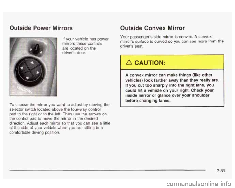
Outside Power Mirrors
If your vehicle has power
mirrors these controls
are located on the
driver’s door.
To choose the mirror you want to adjust by moving the
selector switch located above the four-way control
pad to the right or to the left. Then use the arrows on
the control pad
to move the mirror in the desired
direction. Adjust each mirror
so that you can see a little
comfortable driving position.
VI LI IG JIUG VI YVUl VGIIlblG VVIIbII YVU Ulb QlLLlllLJ Ill U n$ +hn nidn n$ .,nsnr n,nh:nIn %a,hnw. nrn -;++in- ;n n
Outside Convex Mirror
Your passenger’s side mirror is convex. A convex
mirror’s surface
is curved so you can see more from the
driver’s seat.
A convex mirror can make things (like o ?r
vehicles)
look farther away than they really are.
If you cut too sharply into the right lane, you
could hit a vehicle on your right. Check your
inside mirror or glance over your shoulder
before changing lanes.
2-33
Page 103 of 354

Storage Areas
Glove Box
To open, pull the glove box latch toward you.
Cupholder(s)
Pull down the door on the rear of the center console to
use the rear seat cupholders.
Center Console Storage Area
The center console has two separate storage areas. To
open, pull up on the lid.
2-34
Page 104 of 354
Sunroof
If your vehicle has this feature, the switch is located on
the headliner between the sun visors. The sunroof
will only operate when the ignition is in
ON.
The sunroof can be opened to a vent position or it can
be express-opened all of the way.
To open the sunroof to the vent position, you must first
open the sunshade by hand. Then push the switch
back and release it.
To fully open the sunroof, push the switch back again
and release it. In
both the vent and fully open positions, the air
flow
can be adjusted for driving comfort by pushing and
holding the switch forward until the sunroof moves to
the desired position.
To close the sunroof, push the switch forward and hold
it until the sunroof
is closed. The sunroof will stop if
the switch is released during operation. Remember to
close the sunshade by hand.
The sunroof glass panel cannot be opened or closed
if
your vehicle has an electrical failure.
Notice: Do not attempt to force the sunshade
forward of the sliding glass panel. Damage will
occur and the sunroof may not open or close
properly.
2-35
Page 105 of 354

6 NOTES
2-36
Page 106 of 354
Section 3 Instrument Panel
Instrument Panel Overview ............................... 3.4
Hazard Warning Flashers
.......... .............. 3.6
Other Warning Devices
................................... 3.6
Horn
............................................................. 3.6
Tilt Wheel
..................................................... 3.7
Turn SignaVMultifunction Lever
......................... 3.7
Exterior Lamps
............................................. 3.13
Interior Lamps
.............................................. 3.16
Accessory Power Outlets
............................... 3.17
Ashtrays and Cigarette Lighter
........................ 3.18
Climate Controls
........................................... -3-1 9
Climate Control System
................................. 3.19
Outlet Adjustment
......................................... 3.22
Warning Lights, Gages and Indicators
............. 3.23
Instrument Panel Cluster
................................ 3.24
Speedometer and Odometer
........................... 3.25
Tachometer
................................................. 3.25
Safety Belt Reminder Light
............................. 3.26
Air
Eag Reauiness iighi 3-LW
Charging System Light .................................. 3.27
fi cln ................................
Up-Shift Light .............................. .......... 3-28
Brake System Warning Light
........, .......... 3-28
Anti-Lock Brake System
Enhanced Traction System
Enhanced Traction System
Warning
bight
........................................ 3-29
Warning Light
........................................... 3-29
Active Light
.............................................. 3-30
Engine Coolant Temperature Gage
.................. 3-31
Low Coolant Warning Light
............................ 3-31
Malfunction Indicator Lamp
............................. 3-31
Oil Pressure Light
......................................... 3-34
Low Oil Level Light
....................................... 3-35
Security Light
............................................... 3-36
Cruise Control Light
...................................... 3-36
%??:ice ‘!ehic!n see!? Light ........................... ._ 2-36
Fuel Gage ................................................... 3-37
Change Engine
Oil Light
................................ 3-35
Low Washer Fluid Warning Light
..................... 3-36
3-
1
Page 107 of 354
Section 3 Instrument Panel
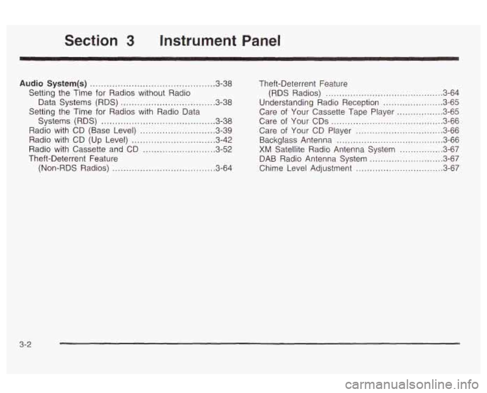
Audio System(s) ............................................. 3.38
Setting the Time for Radios without Radio
Data Systems (RDS)
.................................. 3.38
Setting the Time
for Radios with Radio Data
Systems (RDS)
......................................... 3-38
Radio with CD (Base Level)
........................... 3-39
Radio with CD (Up Level)
.......... , ................ 3.42
Radio with Cassette and CD
... ........ 3.52
Theft-Deterrent Feature (Non-RDS Radios)
.......... .... 3.64 Theft-Deterrent Feature
(RDS Radios) ...................... ............. 3-64
Understanding Radio Reception
...................... 3-65
Care
of Your Cassette Tape Player ................. 3-65
Care of Your CDs
......................................... 3-66
Care of Your CD Player ................................ 3-66
Backglass Antenna
....................................... 3-66
XM Satellite Radio Antenna System ................ 3-67
DAB Radio Antenna System
........................... 3-67
Chime Level Adjustment
............................. 3-67
3-2
Page 108 of 354
cn
W
Page 109 of 354

Page 110 of 354
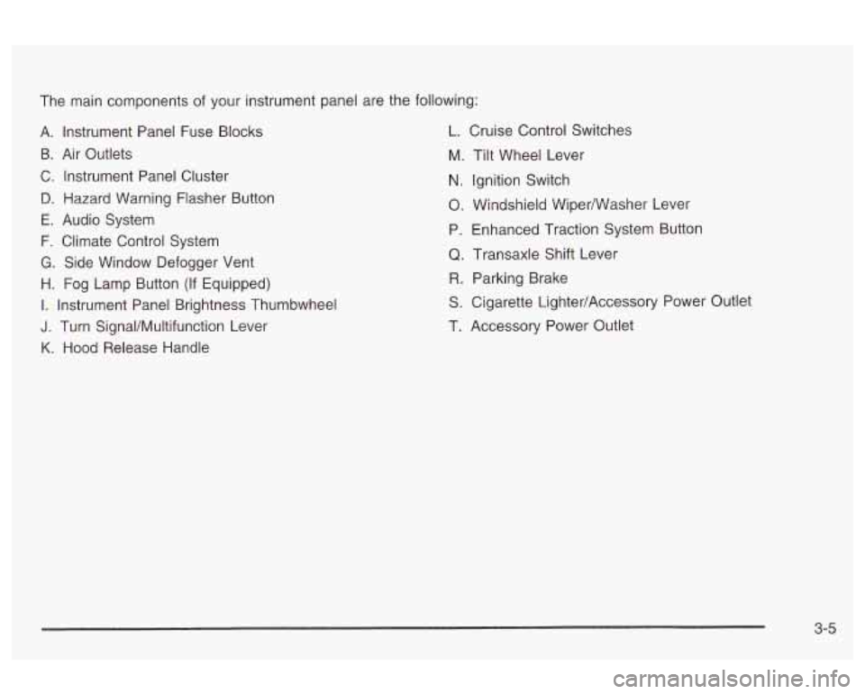
The main components of your instrument panel are the following:
A. Instrument Panel Fuse Blocks L. Cruise Control Switches
B. Air Outlets
C. Instrument Panel Cluster
D. Hazard Warning Flasher Button
E. Audio System
F. Climate Control System
G. Side Window Defogger Vent
H. Fog Lamp Button (If Equipped)
I. Instrument Panel Brightness Thumbwheel
J. Turn SignaVMultifunction Lever
K. Hood Release Handle M.
N.
0.
P,
Q
R
S
T.
Tilt
Wheel Lever
Ignition Switch
Windshieid Wiperwasher Lever
Enhanced Traction System Button
Transaxle Shift Lever Parking Brake
Cigarette Lighter/Accessory Power Outlet
Accessory Power Outlet
3-5