charging OLDSMOBILE BRAVADA 1998 Owners Manual
[x] Cancel search | Manufacturer: OLDSMOBILE, Model Year: 1998, Model line: BRAVADA, Model: OLDSMOBILE BRAVADA 1998Pages: 380, PDF Size: 19.2 MB
Page 11 of 380

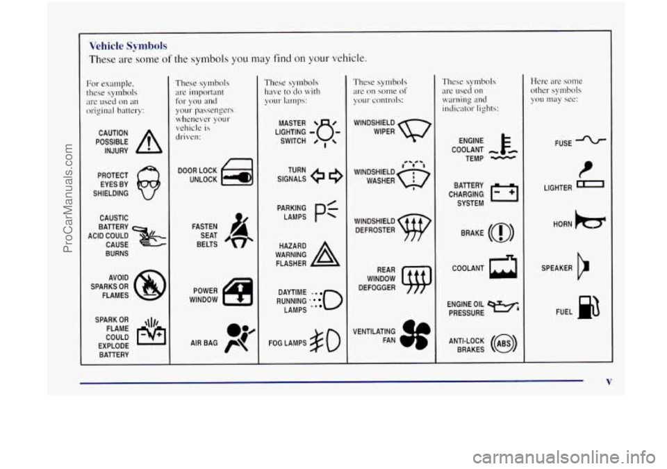
Vehicle Symbols
These are some of the symbols you may find on your vehicle.
For example,
these symbols
are used on
an
original battery:
POSSIBLE A
CAUTION
INJURY
PROTECT EYES BY
SHIELDING
CAUSTIC
ACID COULD
x
BATTERY
CAUSE
BURNS
AVOID
SPARKS
OR
FLAMES
SPARK
OR ,\I/,
COULD
FLAME
EXPLODE BATTERY
These symbols
are important
your passengers
whenever your
vehicle
is
driven:
for
you and
FASTEN
SEAT
BELTS
These symbols
have
to do with
your lamps:
SIGNALS 9
TURN
RUNNING
' 0
DAYTIME .
LAMPS **
FOG LAMPS $0
These symbols
are on some
of
your controls:
WINDSHIELD
WIPER
CS 0b
WINDSHIELD DEFROSTER
WINDOW
DEFOGGER
VEN TlLATlNG
FAN
These symbols are
used on
warning and
indicator lights:
COOLANT -
TEMP -
CHARGING BAllERY
SYSTEM
BRAKE
(0)
COOLANT a
ENGINE OIL w,
PRESSURE
Here are some
other symbols
you may see:
FUSE
LIGHTER
n
HORN )tr
SPEAKER
b
FUEL p3
ANTI-LOCK (@)
BRAKES
V
ProCarManuals.com
Page 111 of 380

The transmitter will learn and transmit the frequencies
of most current transmitters and is powered by your
vehicle’s battery and charging system.
This device complies
with Pcxt 15 of the FCC Rules.
Operation is subject
to the following two conditions:
( I ) this device may not cause Ilarn~ful interference,
and
(2) this device rnust accept any interference received,
including interference that may cause undesired operation.
This device complies
with RSS-210 of Industry Canada.
Operation is subject to the following two conditions:
( 1) this device may not cause interference, and (2) this
device rnust accept any interference, including interference
that may cause undesired operation of the device.
Changes and modifications
to this system by other than
an authorized service facility could void authorization to
use this equipment.
Programming the Transmitter
Do not use the rransrnitter with any garage door opener
that does not have the “stop and reverse” feature. This
includes any garage door opener mode1 manufactured
before April
1. 1982.
Be s1.1~ thcrt people cmcl ol?jec.t.s u1-e dcwr ofthe g~[r~rge
cloor ~vrt (o-e /7t.oSI.Clrlllllirlg!
Your vehicle’s engine should be turned off while
programming the transmitter. Follow these steps to
program
up to three channels:
1. If you have not previously programmed a universal
channel, proceed to Step
2. Otherwise, hold down
the two outside buttons on the universal transmitter
~~ntil the red light begins to flash rapidly
(approximately 20 seconds). Then release the
buttons. This procedure initializes the memory and
erases any previous settings for all three channels.
2. Hold the end of the hand-held transmitter against the
bottom surface of the universal transmitter
so that
YOLI can still see the red light.
3. Decide which one of the three channels you want to
program. Using both hands, press the hand-held
transmitter button and the desired button on the
universal transmitter. Contin~le
to hold both buttons
through Step
4.
4. Hold down both buttons until you see the red light
on the ~~niversal transmitter flash rapidly. The rapid
flashing, which could take
LIP to 90 seconds,
indicates that the universal transmitter
has been
programmed. Release both buttons once the light
starts to flash rapidly.
2-47
ProCarManuals.com
Page 118 of 380

Air Bag Readiness Light
There is an air bag readiness light on the instrument panel,
which shows the air bag symbol. The system checks the
air bag’s electrical system for malfunctions. The light tells
you
if there is an electrical problem. The system check
includes the air bag sensors, the air bag module, the wiring
and the diagnostic module. For more information on the
air
bag system. see “Air Bag“ in the Index.
This light
will come on
when you start your engine,
and
it will flash for a few
seconds. Then the light
should go out. This means
the system
is ready.
If the air bag readiness light stays on after you start the
engine or comes on when you are driving, your air bag
system may not work properly. Have your vehicle
serviced right away.
The air bag readiness light should flash for a few
seconds when
you turn the ignition key to RUN. If the
light doesn’t come on then, have
it fixed so it will be
ready to warn you if there is a problem.
Charging System Indicator ._ Light
1 The charging system light
will come on briefly when
you
turn on the ignition,
but the engine
is not
running, as
a check to
show you
it is working.
It should go out once the engine is running. If it stays
on. or comes
on while you are driving, you may have a
problem with the charging system. It could indicate that
you have problems
with a generator drive belt, or
another electrical problem. Have
it checked right away.
Driving while this light is on could drain your battery.
If you must drive a short distance with the light on, be
certain
to turn off’ all your accessories, such as the radio
and air conditioner.
2-54
ProCarManuals.com
Page 119 of 380

Voltmeter Gage
When your engine is not
running, but the ignition is
on
(in the RUN position),
this gage shows your
battery's state of charge
in
DC volts.
When the engine is running, the gage shows the
condition
of the charging system. Readings between the
low and high warning zones indicate the normal
operating range. Readings
in the
low warning zone may occur when a
large number of electrical accessories are operating
in
the vehicle and the engine is left at an idle for an
extended period. This condition
is normal since the
charging system
is not able to provide full power at
engine idle.
As engine speeds are increased. this
condition should correct itself as higher engine speeds
allow the charging system to create maximum power.
You can only drive for a short time with the reading in
either warning zone. If you must drive, turn off all
unnecessary accessories.
Readings
in either warning zone indicate a possible
problem
in the electrical system. Have the vehicle
serviced
as soon as possible.
ProCarManuals.com
Page 205 of 380

Trailer Wiring Harness
The trailer wiring harness is an eight-wire harness
assembly. The harness
is stored under the vehicle, on the
driver's side corner frame crossmember. The harness has
a 30-amp feed wire
with an inline fuse located by the
junction block. See "Fuses and Circuit Breakers"
in the
Index. The harness does not have
a connector and
should be wired by
a qualified electrical technician. The
technician can use the following color code chart when
connecting
the wiring harness to your trailer.
Dark Blue: Use for electric trailer brakes or
auxiliary wiring.
Red: Use for battery charging; it connects to the
starter solenoid.
Light Green: Back-up lamps.
Brown: Tdillarnps and parking lamps.
Yellow: Left stoplamp and turn signal.
Dark Green: Right stoplamp and turn signal.
White (Heavy Gauge): Ground wire.
White (Light Gauge): Auxiliary stoplamp.
Securely attach the harness to the trailer, then tape
or strap it to your vehicle's frame rail. Be sure you leave
it loose enough so the wiring doesn't bend or break, but
not
so loose that it drags on the ground. Store the
harness
in its original place. Wrap the harness together
and tie
it neatly so it won't be damaged.
ProCarManuals.com
Page 301 of 380

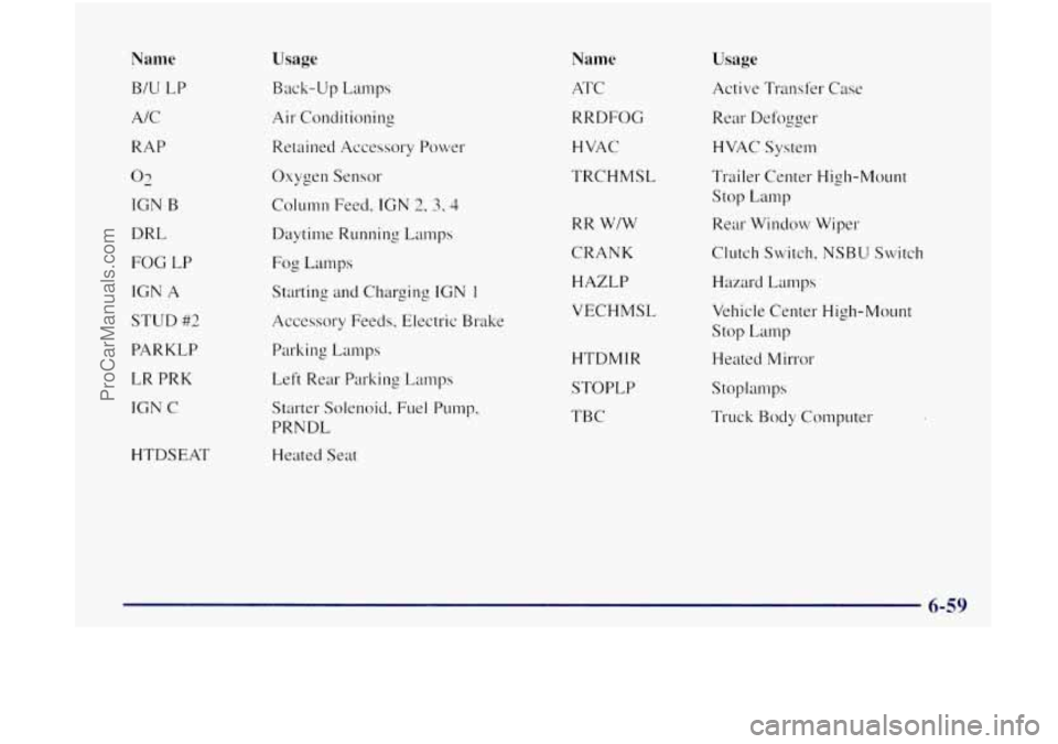
Name
BIU LP
AIC
RAP
02
IGN B
DRL
FOG LP
IGN
A
STUD #2
PARKLP
LR PRK
IGN C
HTDSEAT
Usage
Back-up Lamps
Air Conditioning
Retained Accessory Power
Oxygen Sensor
Column Feed,
IGN 2, 3, 4
Daytime Running Lamps
Fog Lamps
Starting and Charging
IGN 1
Accessory Feeds, Electric Brake
Parking Lamps
Left Rear Parking Lamps
Starter Solenoid. Fuel PLIIIIP,
PRNDL
Heated Seat
Name
ATC
RRDFOG
HVAC
TRCHMSL
RR WIW
CRANK HAZLP
VECHMSL
HTDMTR
STOPLP
TBC
Usage
Active Transfer Case
Rear Defogger HVAC System
Trailer Center High-Mount
stop Lamp
Rear Window Wiper
Clutch Switch, NSBU Switch
Hazard Lamps
Vehicle Center High-Mount
Stop Lamp
Heated Mirror
Stoplan1ps
Truck Body Computer
ProCarManuals.com
Page 366 of 380

Brakes Adjustment
.................................. 6-32
Master Cylinder
.............................. 6-29
PedalTravel
................................. 6-32
Replacing System Parts
........................ 6-32
Trailer
...................................... 4-48
Wear
....................................... 6-31
Brake-Transmission Shift Interlock Check
........... 7-4 I
Braking ........................................ 4-6
In Emergencies ................................ 4-9
Brightness Control
.............................. 2-34
BTSICheck
................................... 7-41
Bulb Replacement .............................. 6-33
Capacities and Specifications
............... 6-60, 6-6 1
Carbon Monoxide ................ 2-9,2-23, 4-41 4-49
Cargo Security
Shade ............................ 2-42
Cargo Tie Downs
............................... 2-42
Certification/Tire Label
.......................... 4-42
Chains Safety
...................................... 4-48
Tire
........................................ 6-44
Changing a Flat Tire
............................. 5-22
Charging System Light
.......................... 2-54
Check Gages Light
.............................. 2-62
Checking Your Restraint System
.................. 1-5 1
Chemical Paint Spotting .......................... 6-5 1
Child Restraints ................................ 1-37
Center Seat Positions
.......................... 1-45
Securing
in a Rear Outside Seat Position ........... 1-43
Securing
in the Right Front Seat Position .......... 1-45
TopStrap ................................... 1-42
Where
to Put ................................ 1-37 Cigarette Lighter
............................... 2-44
Circuit Breakers and Fuses
....................... 6-55
Cleaner.Air
................................... 6-15
Cleanins
Alumnun1 Wheels ............................ 6-50
Exterior Lamps and Lenses ..................... 6-49
Fabric
...................................... 6-46
Glass
....................................... 6-47
Inside
of Your Vehicle ......................... 6-45
Instrument Panel ............................. 6-47
Interior Plastic Components
..................... 6-47
Leather
..................................... 6-47
Outside
of Your Vehicle ........................ 6-48
Stains
...................................... 6-46
Tires
....................................... 6-50
Vinyl
....................................... 6-46
Weatherstrips
................................ 6-48
Wheels
..................................... 6-50
Windshield, Backglass and Wiper Blades .......... 6-48
Climate Control System
........................... 3-2
Clock. Setting
................................... 3-7
Comfort Controls ................................ 3-1
Compact Disc Care ............................. 3-22
Compact Disc Player Care
........................ 3-22
Compact Spare Tire
............................. 5-31
Compass
...................................... 2-38
Control
of a Vehicle .............................. 4-6
Convenience Net
............................... 2-41
Convex Outside Mirror .......................... 2-36
Coolant
....................................... 6-22
Coolant Heater
. Engine .......................... 2-15
Courtesy Transportation
........................... 8-6
Cruise Control ................................. 2-29
9-2
. ..
ProCarManuals.com
Page 369 of 380

Ignition Positions
.................................... 2-12
Transmission Lock Check
...................... 7-42
Illuminated Entry
............................... 2-34
Inflation. Tire
............................. 6.38. 7.39
Inside Daymight Rearview Mirror
................. 2-35
Inspections
Brakesystem
................................ 7-44
Drive Axle
.................................. 7-44
Engine Cooling System
........................ 7-43
Exhaust Systems
............................. 7-43
Front Drive Axle Boot
......................... 7-43
Steering
.................................... 7-43
Throttle System
.............................. 7-44
Transfer Case
................................ 7-44
Instrument Panel
............................... 2-50
Cleaning
.................................... 6-47
Cluster
..................................... 2-51
Interior Lamps
................................. 2-34
Suspension
.................................. 7-43
FuseBlock
.................................. 6-55
Jacking Equipment
............................. 5-23
Jump Starting
................................... 5-3
Keyless Entry System
Operation
.................................... 2-7
Remote Panic Alarm
........................... 2-7
Resynchronization
............................. 2-8
Keys
.......................................... 2-2 Labels
Certification/Tire
............................. 4-42
Fuse
.................................. 6.55. 6.57
Safety Belt
.................................. 1-51
Service Parts Identification ..................... 6-53
Vehicle Identification Number
................... 6-53
Lamps
........................................ 2-32
Dome
...................................... 2-34
Front Reading
........................... 2-34, 2-37
Interior
..................................... 2-34
Leaving Your Vehicle
............................. 2-6
Leaving Your Vehicle with the Engine Running
....... 2-21
Liftgate OnReminder
................................ 2-33
ManualRelease
............................... 2-9
Lighter
....................................... 2-44
Remote Release
.............................. 2-10
Lights Anti-Lock Brake System Warning
............ 2-57, 4-7
Brake System Warning
......................... 2-56
Charging System
............................. 2-54
Gate Ajar
................................... 2-62
LowFuel
................................... 2-63
Safety Belt Reminder
...................... 1-8, 2-53
Security Warning
............................. 2-61
Service Engine Soon
.......................... 2-58
Loading Your Vehicle
........................... 4-42
Locking Rear Axle
.............................. 2-24
Lockout Prevention
.............................. 2-5
CheckGages
................................ 2-62
Service4WD
................................ 2-61
LockoutSwitch
................................ 2-25
9-5
ProCarManuals.com