fuse OLDSMOBILE SILHOUETTE 2003 Owners Manual
[x] Cancel search | Manufacturer: OLDSMOBILE, Model Year: 2003, Model line: SILHOUETTE, Model: OLDSMOBILE SILHOUETTE 2003Pages: 466, PDF Size: 21.55 MB
Page 9 of 466
Front Seats
Manual Seats
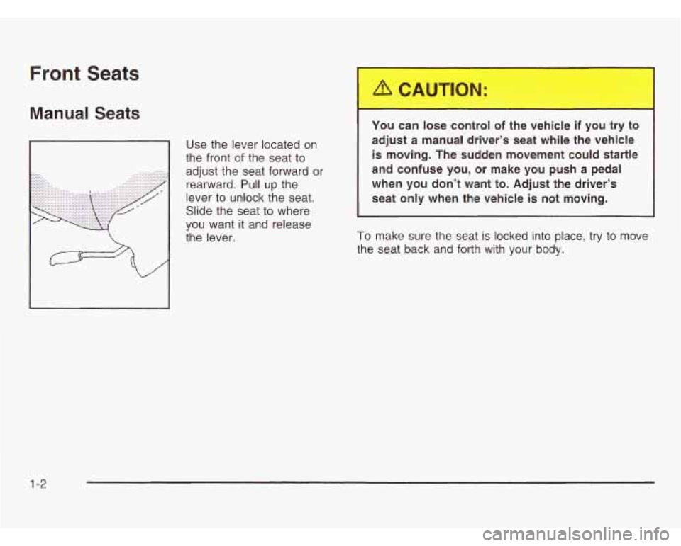
Use the lever located on
the front
of the seat to
adjust the seat forward or
rearward. Pull up the
lever to unlock the seat.
Slide the seat to where
you want it and release
the lever. You can lose control of the vehicle if you try to
adjust a manual driver’s
seat while the vehicle is moving. The sudden movement could startle
and confuse you, or make you push a pedal
when you don’t want to. Adjust the driver’s
seat only when the vehicle is not moving.
To make sure the seat is locked into place, try to move
the seat back and forth with your body.
1 -2
Page 106 of 466
Resetting the Power Sliding Door
The power sliding door may operate incorrectly or not
at all because of the following conditions:
e A low voltage or dead battery,
disconnecting the battery, or
if the instrument panel PWR/HEATED SEAT PSD
fuse or the underhood fuse 8,
27 or 29 are
removed or blown.
See
Fuses and Circuit Breakers on page 5-96 for more
information about your fuse panel.
If any of these conditions occur, the power sliding door
will need to be reset.
If your vehicle has the dual
power sliding doors, both doors will have to be reset.
To do this:
1. Check to be sure the power sliding door is unlocked
2. Turn the ignition key to OFF.
3. !f en, t~rrn the pnwer slidin? door override switch off.
and securely closed.
4. Remove fuse 29 from the underhood fuse block.
Leave
it out for 30 seconds.
5. Reinstall the fuse and wait 10 seconds.
6. Turn the power sliding door override switch on.
7. Press either of the power door lock switches to open
the power sliding door.
8. Open the door all of the way.
9. Wait five seconds and close the door by pressing
either power door lock switch.
IO. Wait five seconds and repeat Steps 7 through 9.
If the door does not rest in the fully open position
after repeating Step
7, repeat Steps 7 through 9 again.
If the door still does not operate correctly, see your
dealer for service.
2-2 1
Page 115 of 466

PASS-Key@ 111 Operation
Your vehicle is equipped
with the PASS-Key@
Ill
(Personalized Automotive
Security System)
theft-deterrent system.
PASS-Key@
Ill is a passive
theft deterrent system.
This means you don’t have
to do anything different
to arm or disarm the
system.
It works when you
insert
or remove the key
from the ignition.
When the PASS-Key@
Ill system senses that someone
is using the wrong key, it shuts down the vehicle’s
starter and fuel systems. The starter will not work and
fuel will stop being delivered to the engine. Anyone
using a trial-and-error method
to start the vehicle will be
discouraged because of the high number of electrical
key codes.
If the engine does not start and the security message
comes on, the key may have a damaged transponder.
Turn the ignition
off and try again.
If the engine still does not start, and the key appears to
be undamaged, try another ignition key. At this time,
you may also want
to check the instrument panel PASS
KEY fuse.
If the engine still does not start with the
other key, your vehicle needs service.
If your vehicle
does start, the first key may be faulty. See your dealer or
a locksmith who can service the PASS-Key@ Ill to
have a new key made. See Fuses and Circuit Breakers
on page 5-96.
It is possible for the PASS-Key@ Ill decoder to learn
the transponder value of a new or replacement key.
Up
to 10 additional keys may be programmed for
the vehicle. This procedure is for learning additional
keys only.
If all the currently programmed keys are lost
or do not operate, you must see your dealer or a
locksmith who can service PASS-Key@
Ill to have keys
made and programmed to the system.
See your dealer or a locksmith who can service
PASS-Key@
Ill to get a new key blank that is cut
exactly as the ignition key that operates the system.
2-30
Page 148 of 466
Entering Programming Mode
To program features, your vehicle must be in the
programming mode. Follow these steps:
1. The content theft-deterrent system must be
disarmed. See
Content Theft-Deterrent on
page
2-27.
2. Remove the BCM PRGRM fuse from the instrument
panel fuse block, located to the right of the glove
box. See Fuses and Circuit Breakers on page 5-96.
3. Close the driver’s door
4. Turn the ignition key to ACCESSORY.
5. Count the number of chimes you hear. You will
hear two to four chimes depending on the features
your vehicle is equipped with. Refer to the chart
shown previously.
You can now program your choices.
To exit the programming mode, follow the steps listed
under
Exiting Programming Mode on page 2-71.
Delayed Illumination and
Exit Lighting
This feature allows you to customize the interior lamps
when entering and exiting the vehicle.
Programmable Modes
Mode 1: Both Features Off (The interior lamps will
turn on or
off at the same instant that a door is opened
or closed.)
Mode
2: Delayed Illumination Only (The interior lamps
will stay on for about
25 seconds after all the doors
and liftgate are closed, or until you lock the doors.)
Mode
3: Exit Lighting Only (The interior lamps will
come on whenever you remove the key from the
ignition and stay on for about
25 seconds, or until
you lock the doors.)
Mode
4: Both Features On (This combines
Modes 2 and 3.)
2-63
Page 156 of 466
Before your vehicle was shipped from the factory,
it was programmed in Mode
1. The mode to which the
vehicle was programmed may have been changed since
it left the factory. To determine the mode to which
your vehicle is programmed or to program your vehicle
to a different mode, do the following:
1. Follow the instructions for Entering Programming
Mode on page
2-63.
2. Insert your spare key fully into any door key
cylinder and turn it to the unlock position.
This step is necessary to prevent accidental
programming of this feature to Mode
2. Do not
program this feature to Mode
2 without first
reading Mode
2 entirely. The door key cylinder
must remain in the unlock position during
Steps
2 through 4.
3. Press the button with the horn symbol on the
remote keyless entry transmitter.
4. Count the number of chimes you hear.
The number of chimes indicates the vehicle's
curreni programmed mode.
(ii you ao not wish io
change the current mode, you can either exit
the programming mode by following the instructions
later in this section or program the next feature
available on your vehicle.)
5. Press the panic button to change the current mode.
6. Press the panic button until you hear the number
of chimes corresponding to the mode selection
you want.
7. Remove your key from the door key cylinder.
The mode you selected is now set. You can either exit
the programming mode by following the instructions
next in this section or program the next feature available
on your vehicle.
Exiting Programming Mode
To exit programming mode, turn the key from
ACCESSORY to
OFF and put the BCM PRGRM fuse
back into the instrument panel fuse block.
After programming a feature, you can exit the
programming mode at anytime.
Also, if your vehicle
is equipped with the content theft-deterrent system,
remember to arm the svstem before exitinq.
2-71
Page 162 of 466
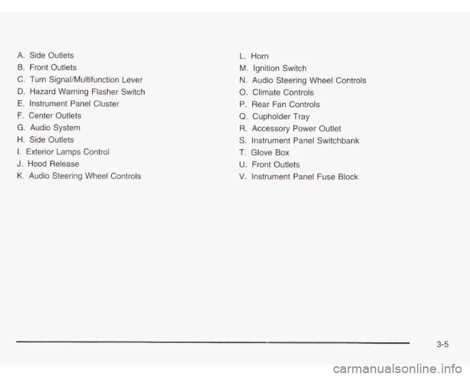
A. Side Outlets
B. Front Outlets
C. Turn SignaVMultifunction Lever
D. Hazard Warning Flasher Switch
E. Instrument Panel Cluster
F. Center Outlets
G. Audio System
H. Side Outlets
I. Exterior Lamps Control
J. Hood Release
K. Audio Steering Wheel Controls
L. Horn
M. Ignition Switch
N. Audio Steering Wheel Controls
0. Climate Controls
P. Rear Fan Controls
Q. Cupholder Tray
R. Accessory Power Outlet
S. Instrument Panel Switchbank
T. Glove Box
U. Front Outlets
V. Instrument Panel Fuse Block
3-5
Page 165 of 466
Turn and Lane-Change Signals
The turn signal has two upward (for right) and two
downward (for left) positions. These positions allow you
to signal a turn or a lane change.
To signal a turn, move the lever all the way up or
down. When the turn is finished, the lever will return
automatically.
-1 An arrow on the instrument
panel cluster will flash in
the direction of the
turn or lane change.
To signal a lane change, just raise or lower the lever
until the arrow starts to flash. Hold it there until you
complete your lane change. The lever will return by itself
when you release it.
As you signal a turn or a lane change,
if the arrow
flashes faster than normal, a signal bulb may be
burned out and other drivers won’t see your turn signal.
If a bulb is burned out, replace it to help avoid an
accident. If the arrows don’t go on at all when you signal
a turn, check for burned-out bulbs and check the
fuse. See
Bulb Replacement on page 5-52 and Fuses
and Circuit Breakers on page
5-96.
If you have a trailer towing option with added wiring for
the trailer lamps, the signal indicator will flash at a normal
rate even
if a turn signal bulb is burned out. Check the
front and rear turn signal lamps regularly to make sure
they are working.
Turn Signal On Chime
If either turn signal is left on for more than 3/4 mile
(1.2 km), a chime will sound to let the driver know to
turn
it off.
If you need to leave the signal on for more than 3/4 mile
(1.2 km), turn off the signal and then turn it back on.
Headlamp High/Low-Beam Changer
To change the headlamps from high to low beam, or
low to high, simply pull the turn signal lever all the way
toward you. Then release it.
When the high beams
are on, this light on the
instrument panel cluster
will also be on.
Your fog lamps will turn
off when you switch to
high beams. Using your high beams in fog is not
recommended.
3-8
Page 181 of 466
Accessory Power Outlets
With accessory power outlets you can plug in electrical equipment such as
a cellular telephone or CB radio.
The front accessory power outlet is located below
the cupholder drawer.
Pull the cover down to use the accessory power outlet.
When not in use, keep the cover on.
The rear accessory power outlet is located in the rear
compartment on the driver’s side next to the air
inflator system.
To remove the cover, pull the tab on the cover and
pull it
off. To put the cover back on, line up the tabs at
the back of the cover and put the cover
in place.
Push down the tab to secure the cover. When not in
use, always cover the rear accessory power outlet with
the protective cap.
Notice: When using an accessory power outlet,
maximum electrical load must not exceed
20 amps.
Always turn
off any electrical equipment when
not
in use. Leaving electrical equipment on for
extended periods will drain your battery. Certain electrical
accessories may not be compatible
with the accessory power outlet and could result
in blown vehicle or adapter fuses. If you experience
a
problem see your dealer for additional information
on accessory power outlets.
Notice: Adding some electrical equipment to your
vehicle can damage
it or keep other things from
working as they should. This wouldn’t be covered
by your warranty. Check with your dealer before
adding electrical equipment, and never use anything
that exceeds the amperage rating.
When adding electrical equipment, be sure to follow
the proper installation instructions included with
the equipment.
Notice: Power outlets are designed for accessory
plugs only.
Do not hang any type of accessory
or accessory bracket from the plug. Improper use
of the power outlet can cause damage not covered
by your warranty.
3-24
Page 309 of 466
Section 5 Service and Appearance Care
Appearance Care ............................................ 5.87
Care of Safety Belts ...................................... 5-90
Weatherstrips
............................................... 5-90
Sheet Metal Damage
..................................... 5.92
Finish Damage
............................................. 5.92
Underbody Maintenance
................................ 5.93
Chemical Paint Spotting
................................. 5.93
GM Vehicle Care/Appearance Materials
........... 5.93
Cleaning
the Inside
of Your Vehicle ................. 5-87
Cleaning the Outside of Your Vehicle ................. 5-90 Vehicle
Identification
........................ ...... 5.95
Vehicle Identification Number (VIN)
... ...... 5.95
Service Parts Identification Label
... ...... 5.95
Electrical System
.......................... .......... 5.96
Add-on Electrical Equipment
...................... 5.96
Headlamp Wiring
.......................................... 5.96
Windshield Wiper Fuses
................................ 5.96
Power Windows and Other Power Options
....... 5.96
Fuses and Circuit Breakers
............................ 5.96
Capacities and Specifications
........................ 5.103
Normal Maintenance Replacement Parts
......... 5.105
5-2
Page 311 of 466
You should keep a record with all parts receipts and list
the mileage and the date
of any service work you
perform. See Part
E: Maintenance Record on page 6-18.
-.- I
You can be injured and your vehicle could be
damaged if you try to do service work on a
vehicle without knowing enough about
it.
Be sure you have sufficient knowledge,
experience, the proper replacement parts and tools before you attempt any vehicle maintenance task.
Be sure to use the proper nuts, bolts and
other fasteners. “English” and “metric”
fasteners can be easily confused. If you
use the wrong fasteners, parts can later
break or fall off. You could be
hurt.
Adding Equipment to the Outside of
Your Vehicle
Things you might add to the outside of your vehicle
can affect the airflow around it. This may cause
wind noise and affect windshield washer performance.
Check with your dealer before adding equipment
to
the outside of your vehicle.
5-4