check engine light OPEL ANTARA 2017.5 Manual user
[x] Cancel search | Manufacturer: OPEL, Model Year: 2017.5, Model line: ANTARA, Model: OPEL ANTARA 2017.5Pages: 225, PDF Size: 6.2 MB
Page 19 of 225
![OPEL ANTARA 2017.5 Manual user In brief17Automatic transmissionP:parkR:reverseN:neutralD:drive
Manual mode: move selector lever
from D to the left.
<:higher gear]:lower gear
The selector lever can only be moved
out of P when the OPEL ANTARA 2017.5 Manual user In brief17Automatic transmissionP:parkR:reverseN:neutralD:drive
Manual mode: move selector lever
from D to the left.
<:higher gear]:lower gear
The selector lever can only be moved
out of P when the](/img/37/18759/w960_18759-18.png)
In brief17Automatic transmissionP:parkR:reverseN:neutralD:drive
Manual mode: move selector lever
from D to the left.
<:higher gear]:lower gear
The selector lever can only be moved
out of P when the ignition is on and
the foot brake is applied. To engage
P or R, push the release button.
Automatic transmission 3 136.
Starting off
Check before starting off ● Tyre pressure and condition 3 182, 3 212.
● Engine oil level and fluid levels 3 159.
● All windows, mirrors, exterior lighting and number plates are
free from dirt, snow and ice and
are operational.
● Proper position of mirrors, seats, and seat belts 3 28, 3 36,
3 42.
● Brake function at low speed, particularly if the brakes are wet.Starting the engine
● Turn key to position ACC
● move the steering wheel slightly to release the steering wheel lock
● manual transmission in neutral
● operate clutch and brake pedals ● automatic transmission in P or N
● do not accelerate
● diesel engines: turn key to ON for
preheating and wait until control
indicator ! extinguishes
● turn key to START and release
Starting the engine 3 125.
Page 30 of 225
28Keys, doors and windowslights flash simultaneously. The
number and duration of alarm signals are stipulated by legislation.
The alarm can be silenced by
pressing any button of the radio
remote control or manually unlocking
the driver's door with the ignition key.
The anti-theft alarm system is
deactivated at the same time.
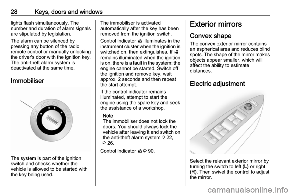
Immobiliser
The system is part of the ignition
switch and checks whether the
vehicle is allowed to be started with the key being used.
The immobiliser is activated
automatically after the key has been
removed from the ignition switch.
Control indicator d illuminates in the
instrument cluster when the ignition is switched on, then extinguishes. If d
remains illuminated when the ignition
is on, there is a fault in the system; the
engine cannot be started. Switch off
the ignition and remove key, wait
approx. 2 seconds and then repeat
the start attempt.
If the control indicator remains
illuminated, attempt to start the
engine using the spare key and seek
the assistance of a workshop.
Note
The immobiliser does not lock the
doors. You should always lock the
vehicle after leaving it and switch on the anti-theft alarm system 3 22,
3 26.
Control indicator d 3 90.Exterior mirrors
Convex shape
The convex exterior mirror contains
an aspherical area and reduces blind spots. The shape of the mirror makes objects appear smaller, which will
affect the ability to estimate
distances.
Electric adjustment
Select the relevant exterior mirror by
turning the switch to left (L) or right
(R) . Then swivel the control to adjust
the mirror.
Page 86 of 225
84Instruments and controls9Danger
Risk of fatal injury for a child using
a child restraint system together
with activated front passenger
airbag.
Risk of fatal injury for an adult
person with deactivated front
passenger airbag.
Airbag deactivation 3 50.
Charging system p illuminates red.
Illuminates when the ignition is
switched on and extinguishes shortly after the engine starts. If it does not
illuminate, seek the assistance of a
workshop.
Illuminates when the engine is
running
Stop vehicle and switch off engine.
Battery is not charging. Engine
cooling may be interrupted. The
brake servo unit may cease to be
effective.
Interrupt your journey immediately.
Remove key and check drive belt
condition and tensioning before
seeking the assistance of a
workshop.
Malfunction indicator light Z illuminates or flashes yellow.
Illuminates when the ignition is
switched on and extinguishes shortly
after the engine starts. If it does not
illuminate, seek the assistance of a
workshop.
Can illuminate briefly when driving;
this is normal and does not indicate a system fault.
Illuminates when the engine is
running
Fault in the emission control system.
The permitted emission limits may be exceeded. Fuel economy and vehicle
driveability may be impaired. Seek
the assistance of a workshop
immediately.
Control indicator Z also illuminates if
there is a fault in the diesel particle
filter 3 129 or with the automatictransmission 3 138. Seek the
assistance of a workshop as soon as
possible.
Ensure the fuel filler cap is screwed in completely 3 150.
Flashes when the engine is
running
Fault that could lead to catalytic
converter damage 3 130 . Ease up on
the accelerator until the flashing
stops. Seek the assistance of a
workshop immediately.
Service vehicle soon g illuminates yellow.
Illuminates when the engine is
running to indicate a fault in the
engine or transmission electronics.
The electronics switch to an
emergency running programme, fuel
consumption may be increased and
vehicle handling may be impaired.
In some cases, the fault can be
eliminated by switching the engine off
and back on again. If g illuminates
again after restarting the engine, the vehicle may need a service.
Page 101 of 225
Instruments and controls99Always day design; black or coloured
text on a light background.
Always night design ; white or
coloured text on a dark background.
Selections are indicated by a o in
front of the menu item.
Ignition logic
See Infotainment manual.Vehicle messages
Warning chimes When starting the engine or whilst
driving
Only one warning chime will sound at a time.
The warning chime regarding
unfastened seat belts has priority
over any other warning chime.
● If seat belt is not fastened.
● When operating the turn and lane-change signals.
● When the vehicle is being driven and the electrical parking brake isapplied 3 143.
● When releasing the electrical parking brake without applying
the foot brake 3 90.
● If there is a fault in the braking system 3 85.
● If the parking assist detects an object 3 148.● During automatic self-cleaning of
the diesel particle filter 3 129.
● In vehicles equipped with engine overspeed warning; when
vehicle speed exceeds 120 km/h
3 91.
When the vehicle is parked and/or the driver's door is opened
● When the key is in the ignition switch.
● With exterior lights on.
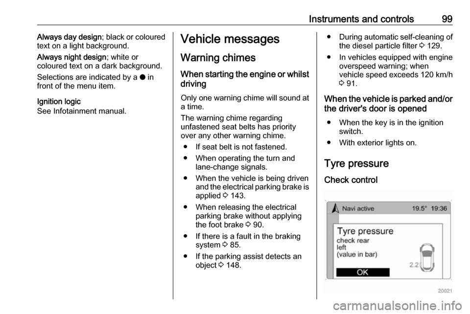
Tyre pressure
Check control
Page 155 of 225

Driving and operating153Adjust tyre pressure to the value
specified for full load 3 212.
Trailer towing Trailer loadsThe permissible trailer loads are
vehicle-dependent and engine-
dependent maximum values which
must not be exceeded. The actual
trailer load is the difference between
the actual gross weight of the trailer
and the actual coupling socket load
with the trailer coupled.
When the trailer load is being
checked, therefore, only the trailer
wheels - and not the jockey wheel -
must be standing on the weighing
apparatus.
The permissible trailer loads are
specified in the vehicle documents. In general, they are valid for gradients
up to max. 12%.
The permitted trailer load applies up
to the specified incline and up to an
altitude of 1000 metres above sea
level. Since engine power decreases
as altitude increases due to the airbecoming thinner, therefore reducing
climbing ability, the permissible gross
train weight also decreases by 10%
for every 1000 metres of additional
altitude. The gross train weight does
not have to be reduced when driving
on roads with slight inclines (less than
8%, e.g. motorways).
The permissible gross train weight
must not be exceeded. This weight is specified on the identification plate3 205.
Vertical coupling load
The vertical coupling load is the load
exerted by the trailer on the coupling
ball. It can be varied by changing the
weight distribution when loading the
trailer.
The maximum permissible vertical
coupling load (80 kg) is specified on
the towing equipment identification
plate and in the vehicle documents.
Always aim for the maximum load,
especially in the case of heavy
trailers. The vertical coupling load
should never fall below 25 kg.When measuring the vertical coupling
load, ensure the drawbar of the
loaded trailer is at the same height as it will be when the trailer is coupled
with the towing vehicle loaded. This is
particularly important for trailers with
tandem axle.
Rear axle load
When the trailer is coupled and the
towing vehicle is fully loaded
(including all occupants), the
permissible rear axle load (see
identification plate or vehicle
documents) must not be exceeded.
National regulations regarding
maximum speeds for vehicles towing a trailer must be observed.
Towing equipmentCaution
When operating without a trailer,
remove the coupling ball bar.
Page 158 of 225

156Vehicle careVehicle careGeneral Information...................157
Accessories and vehicle modifications .......................... 157
Vehicle storage ........................157
End-of-life vehicle recovery .....158
Vehicle checks ........................... 158
Performing work ......................158
Bonnet ..................................... 158
Engine oil ................................. 159
Engine coolant ......................... 160
Power steering fluid .................161
Washer fluid ............................ 161
Brakes ..................................... 161
Brake fluid ............................... 162
Clutch fluid ............................... 162
Vehicle battery ......................... 162
Diesel fuel filter ........................164
Diesel fuel system bleeding .....165
Wiper blade replacement ........165
Bulb replacement .......................165
Headlights ............................... 165
Halogen headlights ..................166
Xenon headlights .....................167
Fog lights ................................. 168
Tail lights ................................. 169Side turn signal lights ..............170
Centre high-mounted brake light ......................................... 170
Number plate light ...................170
Interior lights ............................ 170
Instrument panel illumination ...171
Electrical system ........................171
Fuses ....................................... 171
Engine compartment fuse box . 173
Instrument panel fuse box .......176
Vehicle tools .............................. 179
Tools ........................................ 179
Wheels and tyres .......................181
Winter tyres ............................. 181
Tyre designations ....................181
Tyre pressure .......................... 182
Tyre pressure monitoring system .................................... 183
Tread depth ............................. 186
Changing tyre and wheel size . 186
Wheel covers ........................... 187
Tyre chains .............................. 187
Tyre repair kit .......................... 187
Wheel changing .......................190
Spare wheel ............................ 193
Jump starting ............................. 194
Towing ....................................... 196
Towing the vehicle ...................196
Towing another vehicle ...........197Appearance care .......................198
Exterior care ............................ 198
Interior care ............................. 200
Page 160 of 225
158Vehicle careEnd-of-life vehicle recoveryInformation on end-of-life vehicle
recovery centres and the recycling of
end-of-life vehicles is available on our website, where legally required. Only
entrust this work to an authorised
recycling centre.Vehicle checks
Performing work9 Warning
Only perform engine compartment
checks when the ignition is off.
The cooling fan may start
operating even if the ignition is off.
9 Danger
The ignition system and Xenon
headlights use extremely high
voltage. Do not touch.
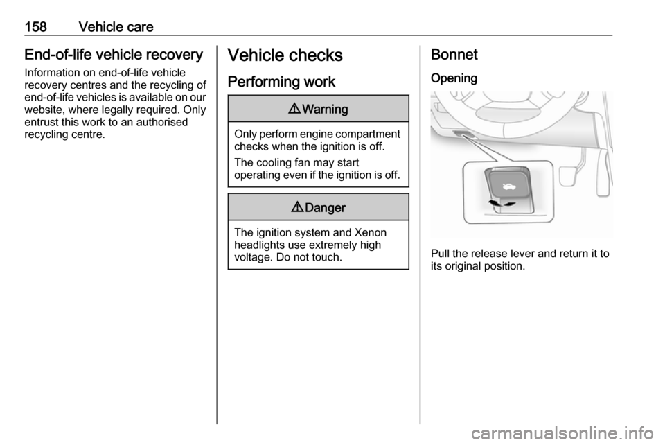
Bonnet
Opening
Pull the release lever and return it to
its original position.
Page 161 of 225
Vehicle care159
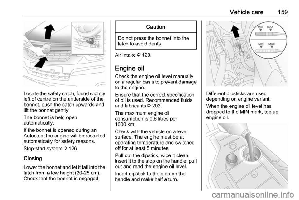
Locate the safety catch, found slightlyleft of centre on the underside of the
bonnet, push the catch upwards and
lift the bonnet gently.
The bonnet is held open
automatically.
If the bonnet is opened during an
Autostop, the engine will be restarted automatically for safety reasons.
Stop-start system 3 126.
Closing
Lower the bonnet and let it fall into the latch from a low height (20-25 cm).
Check that the bonnet is engaged.
Caution
Do not press the bonnet into the
latch to avoid dents.
Air intake 3 120.
Engine oil
Check the engine oil level manually
on a regular basis to prevent damage
to the engine.
Ensure that the correct specification
of oil is used. Recommended fluids
and lubricants 3 202.
The maximum engine oil
consumption is 0.6 litres per
1000 km.
Check with the vehicle on a level
surface. The engine must be at
operating temperature and switched
off for at least 5 minutes.
Pull out the dipstick, wipe it clean, insert it to the stop on the handle, pull
out and read the engine oil level.
Insert dipstick to the stop on the
handle and make half a turn.
Different dipsticks are used
depending on engine variant.
When the engine oil level has
dropped to the MIN mark, top up
engine oil.
Page 167 of 225
Vehicle care165With engine switched off, turn ignition
key to ON, wait approx. 5 seconds,
and turn key to LOCK to perform
priming operation. Perform this
operation 3 times or more while the
engine is switched off, to avoid air
entering the fuel line.
Check diesel fuel filter at shorter
intervals if the vehicle is subjected to
extreme operating conditions.
If there is water in the diesel fuel filter, control indicator U illuminates in the
instrument cluster 3 90. Drain the
water immediately.
Diesel fuel system bleeding
If the fuel tank has been run dry, the
diesel fuel system must be bled.
Switch on the ignition three times for
15 seconds at a time. Then crank the
engine for a maximum of
40 seconds. If the engine will not start, wait at least 10 seconds before trying
again. If the engine fails to start, seek the assistance of a workshop.Wiper blade replacement
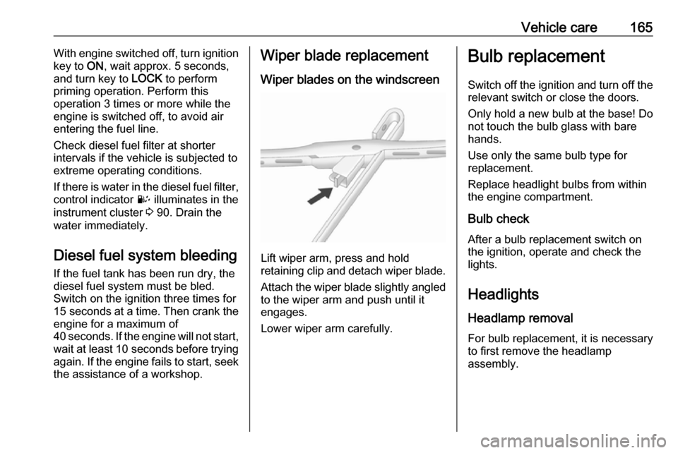
Wiper blades on the windscreen
Lift wiper arm, press and hold
retaining clip and detach wiper blade.
Attach the wiper blade slightly angled
to the wiper arm and push until it
engages.
Lower wiper arm carefully.
Bulb replacement
Switch off the ignition and turn off the
relevant switch or close the doors.
Only hold a new bulb at the base! Do not touch the bulb glass with bare
hands.
Use only the same bulb type for
replacement.
Replace headlight bulbs from within
the engine compartment.
Bulb check
After a bulb replacement switch on
the ignition, operate and check the
lights.
Headlights Headlamp removal
For bulb replacement, it is necessary
to first remove the headlamp
assembly.
Page 221 of 225

219Centre high-mounted brakelight.................................. 109, 170
Change engine oil .......................89
Changing tyre and wheel size ...186
Charging system .......................... 84
Check control................................ 99
Child locks ................................... 23
Child restraint installation locations ................................... 52
Child restraints.............................. 51
Child restraint systems ................51
Cleaning the vehicle ...................198
Climate control ............................. 15
Climate control systems .............114
Clock ............................................ 75
Clutch fluid .................................. 162
Coin storage ................................. 56
Collision damage repair ..............215
Console box.................................. 58
Console net .................................. 56
Control indicators.......................... 80
Control of the vehicle .................123
Controls ........................................ 72
Controls in steering wheel ............72
Convex shape .............................. 28
Coolant and antifreeze ...............202
Coupling ball bar ........................153
Cruise control ...................... 91, 147
Cupholders .................................. 57
Curtain airbag system .................. 49D
Danger, Warnings and Cautions ...4
Daytime running lights ...............107
Declaration of conformity ............213
DEF ............................................ 131
Descent control system .......86, 146
Diesel exhaust fluid ....................131
Diesel fuel filter .......................... 164
Diesel fuel system bleeding .......165
Diesel particle filter .........84, 88, 129
Door open .................................... 91
Doors ............................................ 24
Drain fuel filter ............................. 90
Drink holders ................................ 57
Driver assistance systems ..........147
Driver Information Centre .............91
Driving characteristics and towing tips .............................. 152
Driving economically................... 122
Driving hints ........................ 122, 123
E Electric adjustment ......................28
Electrical parking brake ........85, 143
Electrical parking brake fault ........85
Electrical system......................... 171
Electric power steering ...............124
Electronic climate control system 116
Electronic driving programmes ..138
Electronic Stability Control ..87, 145Electronic Stability Control off....... 87
End-of-life vehicle recovery .......158
Engine compartment fuse box ...173
Engine coolant ........................... 160
Engine coolant temperature ........87
Engine data ............................... 207
Engine exhaust .......................... 129
Engine identification ...................205
Engine oil ................... 159, 202, 206
Engine oil life monitor ...................89
Engine oil pressure ......................88
Entry lighting .............................. 112
Event data recorders ..................215
Exhaust gases ............................ 129
Exit lighting ................................ 112
Exterior care .............................. 198
Exterior lighting ....................13, 105
Exterior mirrors ............................. 28
F Fault ........................................... 138
Fire extinguisher ........................... 69
First aid kit ................................... 69
Fixed air vents ........................... 120
Flex-Fix system ............................ 58
Fog light ....................................... 90
Fog lights .................... 108, 109, 168
Folding mirrors ............................. 29
Front airbag system .....................48
Front fog lights ........................... 108