fuse OPEL ANTARA 2017.5 Manual user
[x] Cancel search | Manufacturer: OPEL, Model Year: 2017.5, Model line: ANTARA, Model: OPEL ANTARA 2017.5Pages: 225, PDF Size: 6.2 MB
Page 13 of 225

In brief111Side air vents .....................119
2 Fixed air vents .................... 120
3 High beam .......................... 106
Headlight flash ...................106
Turn and lane-change
signals ................................ 108
Exit lighting ......................... 112
Parking lights .....................109
Cruise control ....................... 91
4 Remote control on
steering wheel ......................72
Trip computer .....................100
5 Horn ..................................... 72
6 Instruments .......................... 78
Driver Information Centre ...... 91
7 Windscreen wiper and
washer system, headlight
washer system .....................73
Rear window wiper and
washer system .....................748Info-Display .......................... 94
Check control, tyre
pressure monitoring
system ................................ 183
Trip computer .....................100
9 Centre air vents .................. 119
10 Hazard warning flashers ....107
Parking assist ..................... 148
Electronic Stability Control . 145
Descent control system ...... 146
Status LED for anti-theft
alarm system ........................ 26
Folding exterior mirrors ........29
Fuel economy mode ...........122
11 Infotainment system .............10
12 Front passenger airbag ........48
13 Status LEDs for front
passenger airbag .................50
Control indicator for front
passenger seat belt .............42
14 Glovebox .............................. 57
15 Fuse box ............................ 17616Climate control system ....... 114
17 Ignition switch with
steering wheel lock ............125
18 Accelerator pedal ...............124
19 Driver airbag ........................ 48
20 Brake pedal ........................ 142
21 Clutch pedal ....................... 123
22 Steering wheel adjustment ..72
23 Bonnet release ...................158
24 Coin storage ......................... 56
25 Card holder .......................... 56
26 Light switch ........................ 105
Automatic light control .......106
Instrument illumination .......110
Rear fog light ...................... 109
Front fog lights ...................108
Headlight range
adjustment ......................... 106
Page 85 of 225

Instruments and controls83(Door open 3 91aAnti-theft alarm system
3 91
Turn signal
O illuminates or flashes green.
The relevant control indicator flashes
when the turn signal is switched on
3 108.
Rapid flashing: failure of a turn signal
bulb or the associated fuse or failure
of a turn signal light on trailer.
Both control indicators flash when the
hazard warning flashers are active
3 107.
Bulb replacement 3 165, Fuses
3 171.
Turn signals 3 108.
Seat belt reminder
Seat belt reminder for front seats
X for driver's seat illuminates or
flashes red.
k for front passenger's seat
illuminates or flashes red, when the
seat is occupied.
When the engine is running, if seat
belt is not engaged, the control
indicator will flash for 100 seconds
then illuminate until seat belt is
fastened.
If vehicle speed exceeds 22 km/h, the
control indicator will flash for
100 seconds along with a warning
chime and remains illuminated until seat belt is fastened.
Fastening the seat belt 3 41.
Front passenger seat belt reminder k
3 42.
Airbag and belt tensioners v illuminates red.
When the ignition is switched on, v
flashes briefly. If it does not flash,
stays lit or flashes during driving,
there is a fault in the airbag system.
Seek the assistance of a workshop. The airbags and belt pretensioners
may fail to trigger in the event of an
accident.Deployment of the belt pretensioners
or airbags is indicated by continuous
illumination of v.9 Warning
Have the cause of the fault
remedied immediately by a
workshop.
Belt pretensioners, airbag system
3 41, 3 45.
Airbag deactivation
* illuminates yellow.
The front passenger airbag is
deactivated.
Page 158 of 225

156Vehicle careVehicle careGeneral Information...................157
Accessories and vehicle modifications .......................... 157
Vehicle storage ........................157
End-of-life vehicle recovery .....158
Vehicle checks ........................... 158
Performing work ......................158
Bonnet ..................................... 158
Engine oil ................................. 159
Engine coolant ......................... 160
Power steering fluid .................161
Washer fluid ............................ 161
Brakes ..................................... 161
Brake fluid ............................... 162
Clutch fluid ............................... 162
Vehicle battery ......................... 162
Diesel fuel filter ........................164
Diesel fuel system bleeding .....165
Wiper blade replacement ........165
Bulb replacement .......................165
Headlights ............................... 165
Halogen headlights ..................166
Xenon headlights .....................167
Fog lights ................................. 168
Tail lights ................................. 169Side turn signal lights ..............170
Centre high-mounted brake light ......................................... 170
Number plate light ...................170
Interior lights ............................ 170
Instrument panel illumination ...171
Electrical system ........................171
Fuses ....................................... 171
Engine compartment fuse box . 173
Instrument panel fuse box .......176
Vehicle tools .............................. 179
Tools ........................................ 179
Wheels and tyres .......................181
Winter tyres ............................. 181
Tyre designations ....................181
Tyre pressure .......................... 182
Tyre pressure monitoring system .................................... 183
Tread depth ............................. 186
Changing tyre and wheel size . 186
Wheel covers ........................... 187
Tyre chains .............................. 187
Tyre repair kit .......................... 187
Wheel changing .......................190
Spare wheel ............................ 193
Jump starting ............................. 194
Towing ....................................... 196
Towing the vehicle ...................196
Towing another vehicle ...........197Appearance care .......................198
Exterior care ............................ 198
Interior care ............................. 200
Page 165 of 225

Vehicle care163
Batteries do not belong in household
waste. They must be disposed of at
an appropriate recycling collection
point.
Laying up the vehicle for more than
6 weeks can lead to battery
discharge. Disconnect the clamp from the negative terminal of the vehicle
battery.
Ensure the ignition is switched off
before connecting or disconnecting
the vehicle battery.
Retrofitted electrical or electronic
accessories can place an additional
load on the vehicle battery or
discharge the battery. Seek the
assistance of a workshop regarding technical possibilities, such as fitting
a more powerful battery.
Ensure the ignition is switched off
before reconnecting the vehicle
battery. Then perform the following
actions:
1. Set date and time in the information display 3 75.
2. If necessary, activate the power windows and sun roof 3 31, 3 33.
In order to prevent the vehicle battery
from discharging, some consumers
such as the courtesy lights
automatically switch off after a delay.
Charge a disconnected vehicle
battery every 6 weeks.
Vehicle battery discharge protection
3 113.
Replacing the vehicle battery Note
Any deviation from the instructions
given in this paragraph may lead to
a temporary deactivation of the stop-
start system.
When the vehicle battery is being
replaced, please ensure that there
are no open ventilation holes in the
vicinity of the positive terminal. If a
ventilation hole is open in this area, itmust be closed off with a dummy cap, and the ventilation in the vicinity of the
negative terminal must be opened.
Only use batteries that allow the fuse
box to be mounted above the vehicle
battery.
In vehicles with an AGM (Absorptive
Glass Mat) battery, make sure to
have the battery replaced with
another AGM battery.
An AGM battery can be identified by
the label on the battery. We
recommend the use of an original
Opel battery.
Page 173 of 225

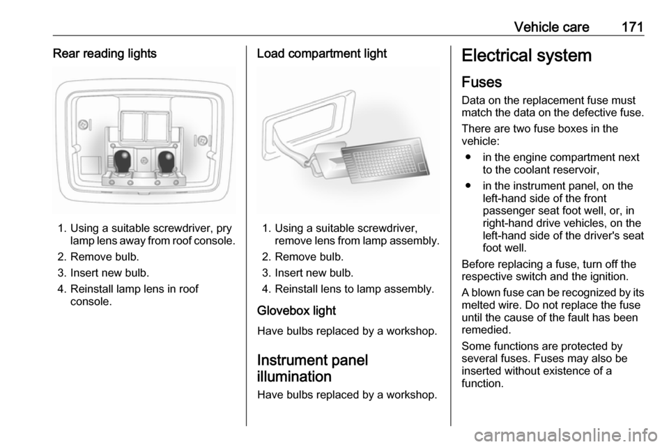
Vehicle care171Rear reading lights
1. Using a suitable screwdriver, prylamp lens away from roof console.
2. Remove bulb.
3. Insert new bulb.
4. Reinstall lamp lens in roof console.
Load compartment light
1. Using a suitable screwdriver,remove lens from lamp assembly.
2. Remove bulb.
3. Insert new bulb.
4. Reinstall lens to lamp assembly.
Glovebox light
Have bulbs replaced by a workshop.
Instrument panel
illumination
Have bulbs replaced by a workshop.
Electrical system
Fuses Data on the replacement fuse must
match the data on the defective fuse.
There are two fuse boxes in the
vehicle:
● in the engine compartment next to the coolant reservoir,
● in the instrument panel, on the left-hand side of the front
passenger seat foot well, or, in
right-hand drive vehicles, on the
left-hand side of the driver's seat
foot well.
Before replacing a fuse, turn off the
respective switch and the ignition.
A blown fuse can be recognized by its melted wire. Do not replace the fuse
until the cause of the fault has been
remedied.
Some functions are protected by
several fuses. Fuses may also be
inserted without existence of a
function.
Page 174 of 225

172Vehicle careNote
Not all fuse box descriptions in this
manual may apply to your vehicle.
When inspecting the fuse box, refer to the fuse box label.
It is advisable to carry a full set of
spare fuses. Spare fuses can be
stored in the engine compartment
fuse box.
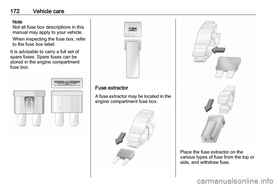
Fuse extractor
A fuse extractor may be located in the engine compartment fuse box.
Place the fuse extractor on the
various types of fuse from the top or
side, and withdraw fuse.
Page 175 of 225

Vehicle care173Engine compartment fusebox
The fuse box is located next to the
coolant reservoir in the engine
compartment.
To open, disengage cover and tilt
upwards.
Page 177 of 225

Vehicle care175FuseCircuitABSAnti-lock Brake
SystemA/CClimate control,
air conditioning
systemAUX PUMPAuxiliary pumpBATT1Instrument panel
fuse boxBATT2Instrument panel
fuse boxBATT3Instrument panel
fuse boxBCMBody Control
ModuleDEF HTRDiesel Exhaust
Fluid HeaterECM1Engine Control
ModuleECM2Engine Control
ModuleFuseCircuitECM PWR TRNEngine Control
Module, Power‐
trainENG SNSREngine sensorsEPBElectrical
parking brakeFRT FOGFront fog lightsFRT WPRFront wiperFUEL/VACFuel pump,
vacuum pumpHDLP WASHERHeadlight
washerHI BEAM LTHigh beam (left-
hand)HI BEAM RTHigh beam
(right-hand)HORNHornHTD WASH/MIRHeated washer
fluid, heated
exterior mirrorsIGN COIL BIgnition coilFuseCircuitLO BEAM LTLow beam (left-
hand)LO BEAM RTLow beam (right-
hand)NOX SNSRNOX SensorPRK LP LTParking light
(left-hand)PRK LP RT/LIFT
GATEParking light
(right-hand), tail‐
gatePWM FANPulse width
modulation fanREAR DEFOGHeated rear
windowREAR WPRRear wiperSPARE–STOP LAMPBrake lightsSTRTRStarter
Page 178 of 225

176Vehicle careFuseCircuitTCMTransmission
Control ModuleTRLR PRL LPTrailer parking
lights
After changing of defective fuses
close the fuse box cover and press
until it engages.
If the fuse box cover is not closed
correctly, malfunctions may occur.
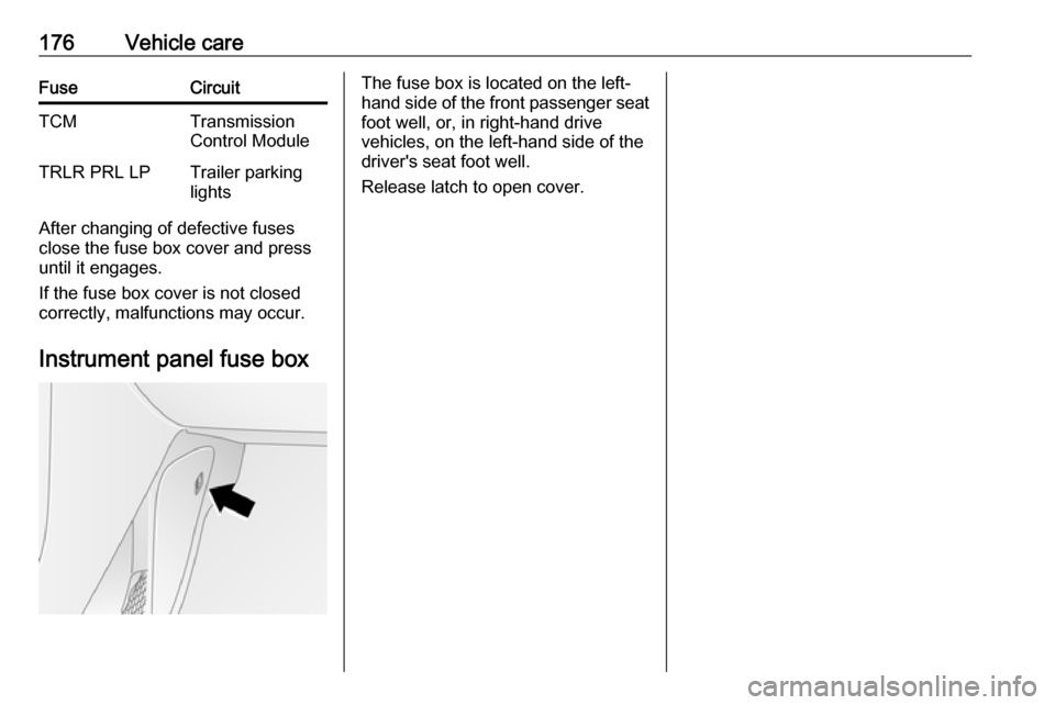
Instrument panel fuse box
The fuse box is located on the left-
hand side of the front passenger seat
foot well, or, in right-hand drive
vehicles, on the left-hand side of the
driver's seat foot well.
Release latch to open cover.
Page 180 of 225

178Vehicle careFuseCircuitAPO JACK
(CONSOLE)Power outlet
(centre
console)APO JACK (REAR
CARGO)Power outlet
(load compart‐
ment)AUDIO/KEY
CAPTUREAudio, key
captureAWD/VENTAll-wheel drive,
ventilationBCM (CTSY)Courtesy lightsBCM (DIMMER)Instrument illu‐
minationBCM (INT LIGHT
TRLR FOG)Interior lights,
trailer fog lightBCM (PRK/TRN)Parking lights,
turn signalsBCM (STOP)Brake lightsBCM (TRN SIG)Turn signalsBCM (VBATT)Battery voltageFuseCircuitCLSTRInstrument
clusterDC/DC
CONVERTERDC, DC
converterDRLDaytime
running lightsDR/LCKDriver door lockDRVR PWR SEATDriver power
seatDRV/PWR WNDWDriver power
windowERAGLONASSEmergency
road assistance
GlonassF/DOOR LOCKFuel filler flapFRT WSRFront washerFSCMFuel systemFSCM/VENT SOLFuel system,
vent solenoidHEATING MAT
SWHeating mat
switchFuseCircuitHTD SEAT PWRSeat heatingHVAC BLWRClimate control,
air conditioning
fanIPCInstrument
panel clusterISRVM/RCMInterior mirror,
remote
compass
moduleL/GATETailgateLOGISTIC MODELogistic modeOSRVMExterior mirrorsPAKSPassive active
keyless startPASS PWR
WNDWPassenger
power windowPWR DIODEPower diodePWR MODINGPower modingRR FOGHeated rear
window