fuse box OPEL ASTRA K 2017 Manual user
[x] Cancel search | Manufacturer: OPEL, Model Year: 2017, Model line: ASTRA K, Model: OPEL ASTRA K 2017Pages: 305, PDF Size: 9.11 MB
Page 13 of 305

In brief111Power windows .....................41
2 Exterior mirrors .....................39
3 Central locking system ..........24
4 Side air vents ...................... 153
5 Cruise control .....................180
Speed limiter ....................... 182
Adaptive cruise control .......184
Forward collision alert .........191
6 Turn and lane-change
signals, headlight flash,
low/high beam, high beam
assist ................................... 140
Exit lighting ......................... 143
Parking lights ...................... 141
Buttons for Driver
Information Centre ..............114
7 Instruments ........................ 104
Driver Information Centre .... 114
8 Buttons for Driver
Information Centre ..............114
9 Forward collision alert
indicator ............................. 19110Windscreen wiper and
washer, rear wiper and
washer ................................. 92
11 Centre air vents .................. 153
12 Info-Display ........................ 119
13 Anti-theft alarm system
status LED ........................... 36
14 Hazard warning flashers ....139
15 Glovebox .............................. 71
16 CD player
17 Controls for Info-Display
operation ............................. 119
18 Climate control system ........ 146
19 Fuse box ............................ 245
Power connector ..................98
20 Traction Control system .....177
Electronic Stability Control . 178
Sport mode ........................ 179
Parking assist/Advanced
parking assist .....................198
Lane keep assist ................213
Eco button for stop-start
system ................................. 161
21 Manual transmission ..........170Automatic transmission ......167
Manual transmission
automated ........................... 171
22 Power outlet .......................... 97
23 Parking brake ......................175
24 Power button ....................... 157
25 Ignition switch .....................156
26 Steering wheel adjustment ..91
27 Horn ..................................... 92
28 Bonnet release lever ..........225
29 Storage compartment ...........72
30 Light switch ........................ 134
Headlight range
adjustment ......................... 135
Front/rear fog lights ............140
Instrument illumination .......142
Page 73 of 305
Storage71StorageStorage compartments................71
Glovebox ................................... 71
Cupholders ................................ 71
Front storage ............................. 72
Armrest storage .........................72
Load compartment .......................73
Load compartment cover ...........79
Rear floor storage cover ............80
Lashing eyes ............................. 81
Cargo management system ......82
Safety net .................................. 84
Warning triangle ........................86
First aid kit ................................. 86
Roof rack system .........................87
Roof rack ................................... 87
Loading information .....................88Storage compartments9Warning
Do not store heavy or sharp
objects in the storage
compartments. Otherwise, the
storage compartment lid could
open and vehicle occupants could be injured by objects being thrown
around in the event of hard
braking, a sudden change in
direction or an accident.
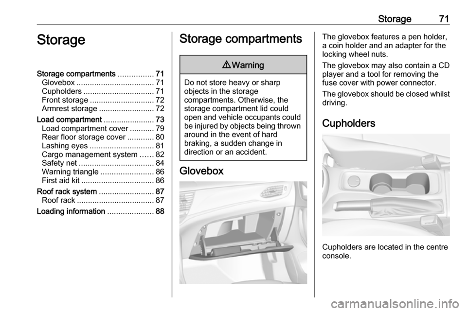
Glovebox
The glovebox features a pen holder,
a coin holder and an adapter for the
locking wheel nuts.
The glovebox may also contain a CD
player and a tool for removing the
fuse cover with power connector.
The glovebox should be closed whilst driving.
Cupholders
Cupholders are located in the centre
console.
Page 100 of 305
98Instruments and controlsSports Tourer: A 12 Volt power outlet
is located at the left sidewall in the
load compartment.
Do not exceed the maximum power
consumption of 120 watts.
With ignition off, the power outlet is
deactivated. Additionally, the power outlet is deactivated in the event of
low vehicle battery voltage.
Electrical accessories that are
connected must comply with the
electromagnetic compatibility
requirements laid down in
DIN VDE 40 839.
Do not connect any current-delivering
accessories, e.g. electrical charging
devices or batteries.
Do not damage the outlets by using
unsuitable plugs.
Stop-start system 3 161.USB charging port
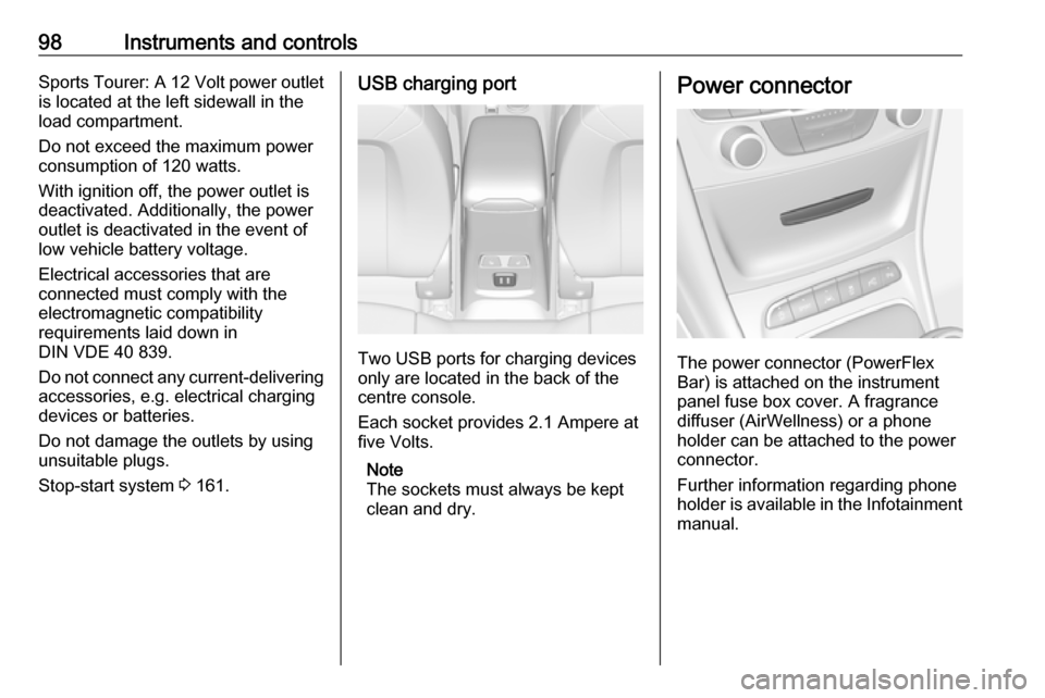
Two USB ports for charging devices
only are located in the back of the
centre console.
Each socket provides 2.1 Ampere at
five Volts.
Note
The sockets must always be kept
clean and dry.
Power connector
The power connector (PowerFlex
Bar) is attached on the instrument
panel fuse box cover. A fragrance
diffuser (AirWellness) or a phone
holder can be attached to the power
connector.
Further information regarding phone
holder is available in the Infotainment
manual.
Page 225 of 305

Vehicle care223Vehicle careGeneral Information...................223
Accessories and vehicle modifications .......................... 223
Vehicle storage ........................224
End-of-life vehicle recovery .....224
Vehicle checks ........................... 225
Performing work ......................225
Bonnet ..................................... 225
Engine oil ................................. 226
Engine coolant ......................... 227
Washer fluid ............................ 228
Brakes ..................................... 228
Brake fluid ............................... 228
Vehicle battery ......................... 229
Diesel fuel system bleeding .....230
Wiper blade replacement ........231
Bulb replacement .......................231
Halogen headlights ..................231
Fog lights ................................. 233
Tail lights ................................. 234
Side turn signal lights ..............240
Number plate light ...................241
Interior lights ............................ 241
Instrument panel illumination ...241Electrical system ........................242
Fuses ....................................... 242
Engine compartment fuse box . 243
Instrument panel fuse box .......245
Load compartment fuse box ....247
Vehicle tools .............................. 249
Tools ........................................ 249
Wheels and tyres .......................250
Winter tyres ............................. 250
Tyre designations ....................250
Tyre pressure .......................... 251
Tyre pressure monitoring system .................................... 252
Tread depth ............................. 256
Changing tyre and wheel size . 256 Wheel covers ........................... 256
Tyre chains .............................. 257
Tyre repair kit .......................... 257
Wheel changing .......................260
Spare wheel ............................ 263
Jump starting ............................. 265
Towing ....................................... 267
Towing the vehicle ...................267
Towing another vehicle ...........268
Appearance care .......................269
Exterior care ............................ 269
Interior care ............................. 271General Information
Accessories and vehiclemodifications
We recommend the use of genuine
parts and accessories and factory
approved parts specific for your
vehicle type. We cannot assess or guarantee reliability of other products
- even if they have a regulatory or
otherwise granted approval.
Any modification, conversion or other
changes made to standard vehicle
specifications (including, without
limitation, software modifications,
modifications of the electronic control units) may invalidate the warranty
offered by Opel. Furthermore, such
changes may impact fuel
consumption, CO 2 emissions and
other emissions of the vehicle and
cause the vehicle to no longer
conform to the type approval,
impacting the validity of your vehicle
registration.
Page 244 of 305
242Vehicle careElectrical systemFuses
Data on the replacement fuse must
match the data on the defective fuse.
There are three fuse boxes in the
vehicle:
● engine compartment● instrument panel
● load compartment
Before replacing a fuse, turn off the
respective switch and the ignition.
A blown fuse can be recognized by its
melted wire. Do not replace the fuse
until the cause of the fault has been
remedied.
Some functions are protected by
several fuses.
Fuses may also be inserted without
existence of a function.
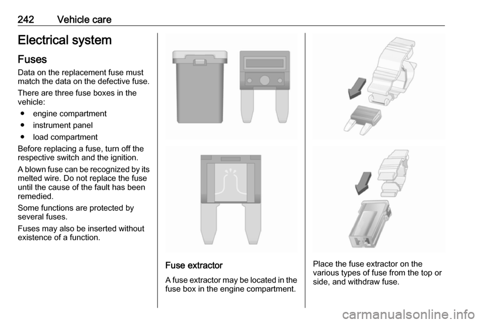
Fuse extractor
A fuse extractor may be located in the fuse box in the engine compartment.Place the fuse extractor on the
various types of fuse from the top or
side, and withdraw fuse.
Page 245 of 305
Vehicle care243Engine compartment fusebox
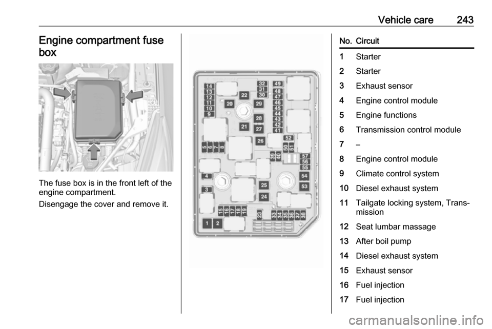
The fuse box is in the front left of the
engine compartment.
Disengage the cover and remove it.
No.Circuit1Starter2Starter3Exhaust sensor4Engine control module5Engine functions6Transmission control module7–8Engine control module9Climate control system10Diesel exhaust system11Tailgate locking system, Trans‐
mission12Seat lumbar massage13After boil pump14Diesel exhaust system15Exhaust sensor16Fuel injection17Fuel injection
Page 246 of 305

244Vehicle careNo.Circuit18Diesel exhaust system19Diesel exhaust system20–21DC/AC Converter22ABS23Washer system for windscreen
and rear window24–25Diesel fuel heating26Transmission control module27Power tailgate module28–29Heated rear window30Mirror defrost31–32DC transformer/LED display/
Electrical heater/Climate
control/Glow plug controllerNo.Circuit33Anti theft warning34Horn35Power outlet load compartment36Right high beam (Halogen)/
Right low beam (LED)37Left high beam (Halogen)38LED headlight/Automatic head‐
light range adjustment39Front fog light40OnStar41Water in fuel sensor/Water
pump42Manual headlight range adjust‐
ment43Fuel pump44Rear view camera/Inside rear
view mirror/Trailer module45LED headlight left/Automatic
headlight range adjustment leftNo.Circuit46Instrument cluster47Steering column lock48Rear wiper49–50LED headlight right/Automatic
headlight range adjustment
right51Left low beam (LED)52Engine control module/Trans‐
mission control module53–54Windscreen wiper55Diesel exhaust system56–57–
After having changed defective fuses,
close the fuse box cover and press
until it engages.
If the fuse box cover is not closed
correctly, malfunction may occur.
Page 247 of 305
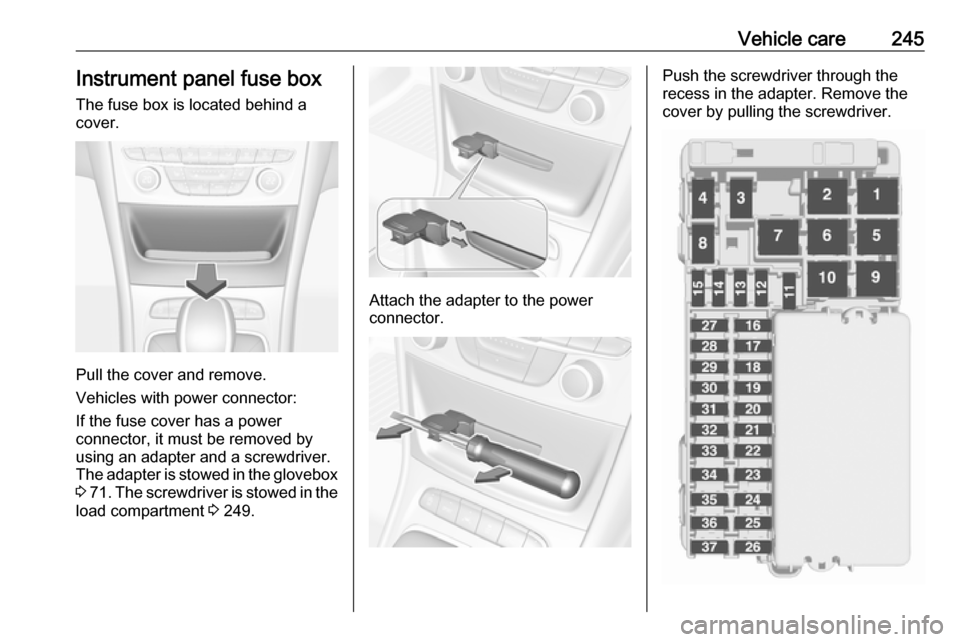
Vehicle care245Instrument panel fuse boxThe fuse box is located behind a
cover.
Pull the cover and remove.
Vehicles with power connector:
If the fuse cover has a power
connector, it must be removed by
using an adapter and a screwdriver.
The adapter is stowed in the glovebox 3 71 . The screwdriver is stowed in the
load compartment 3 249.
Attach the adapter to the power
connector.
Push the screwdriver through the
recess in the adapter. Remove the
cover by pulling the screwdriver.
Page 248 of 305

246Vehicle careNo.Circuit1–2Climate control system, fan3Power seat driver side4Cigarette lighter/Power outlet
front5–6Power window front7ABS8Heated steering wheel9Body control module10Power window rear11Sunroof12Body control module13Seat heating (only on vehicles
without alarm horn)14Exterior mirror15Body control module16Body control moduleNo.Circuit17Body control module18Body control module19Data link connector20Airbag system21Climate control system22Central locking system, tailgate23Electronic key system24Power seat memory function25Airbag system steering wheel26Ignition switch/Steering column
lock27Body control module28USB socket29–30Selector lever31Rear window wiper32Transmission control moduleNo.Circuit33Anti-theft alarm system/Power
sounder34Parking assist/Side blind spot
alert/Infotainment system/USB
socket35OnStar36Info display/Instrument cluster/ CD player37Infotainment system, radio
After having changed defective fuses,
close the fuse box cover and press
until it engages.
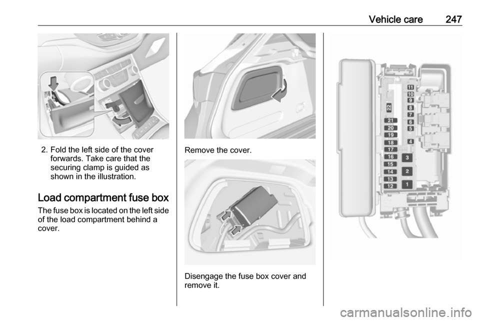
Vehicles with power connector: 1. Apply the cover on the right side.
Page 249 of 305
Vehicle care247
2. Fold the left side of the coverforwards. Take care that thesecuring clamp is guided as
shown in the illustration.
Load compartment fuse box The fuse box is located on the left side
of the load compartment behind a
cover.Remove the cover.
Disengage the fuse box cover and
remove it.