radio OPEL CALIBRA 1988 Service User Guide
[x] Cancel search | Manufacturer: OPEL, Model Year: 1988, Model line: CALIBRA, Model: OPEL CALIBRA 1988Pages: 525, PDF Size: 58.26 MB
Page 121 of 525
Glovebox assembly
Removal
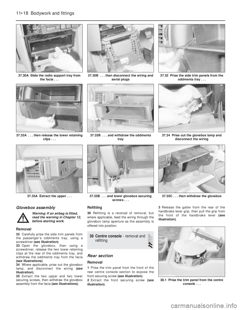
32Carefully prise the side trim panels from
the passenger’s oddments tray, using a
screwdriver (see illustration).
33Open the glovebox, then using a
screwdriver, release the two lower retaining
clips at the rear of the oddments tray, and
withdraw the oddments tray from the facia
(see illustrations).
34Where applicable, prise out the glovebox
lamp, and disconnect the wiring (see
illustration).
35Extract the two upper and two lower
securing screws, then withdraw the glovebox
assembly from the facia (see illustrations).
Refitting
36Refitting is a reversal of removal, but
where applicable, feed the wiring through the
glovebox lamp aperture as the assembly is
offered into position.
38Centre console - removal and
refitting
2
Rear section
Removal
1Prise the trim panel from the front of the
rear centre console section to expose the
front securing screw (see illustration).
2Extract the front securing screw (see
illustration).3Release the gaiter from the rear of the
handbrake lever grip, then pull the grip from
the front of the handbrake lever (see
illustration).
11•18Bodywork and fittings
37.30A Slide the radio support tray from
the facia . . .37.32 Prise the side trim panels from the
oddments tray . . .
37.35C . . . then withdraw the glovebox37.35B . . . and lower glovebox securing
screws . . .37.35A Extract the upper . . .
37.34 Prise out the glovebox lamp and
disconnect the wiring37.33B . . . and withdraw the oddments
tray37.33A . . . then release the lower retaining
clips . . .
37.30B . . . then disconnect the wiring and
aerial plugs
38.1 Prise the trim panel from the centre
console . . .
Warning: If an airbag is fitted,
read the warning in Chapter 12,
before starting work.
Page 184 of 525
tighten the mounting nuts and bolts. On no
account lever at the free end of the alternator,
as serious internal damage could be caused.
3For details of replacement, see Chapter 5.
23Headlamp alignment
2
Refer to Chapter 12 for details.
24Door lock key battery -
replacement
1
1Carefully prise open the outer cover from
the key. Take care not to lose any of the
internal components, as they are loose.
2Remove the battery and discard it safely.
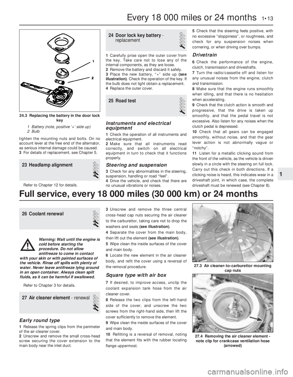
3Place the new battery, “+” side up (see
illustration). Check the operation of the key. If
the bulb does not light obtain a replacement.
4Replace the outer cover.
25Road test
1
Instruments and electrical
equipment
1Check the operation of all instruments and
electrical equipment.
2Make sure that all instruments read
correctly, and switch on all electrical
equipment in turn to check that it functions
properly.
Steering and suspension
3Check for any abnormalities in the steering,
suspension, handling or road “feel”.
4Drive the vehicle, and check that there are
no unusual vibrations or noises.5Check that the steering feels positive, with
no excessive “sloppiness”, or roughness, and
check for any suspension noises when
cornering, or when driving over bumps.
Drivetrain
6Check the performance of the engine,
clutch, transmission and driveshafts.
7Turn the radio/cassette off and listen for
any unusual noises from the engine, clutch
and transmission.
8Make sure that the engine runs smoothly
when idling, and that there is no hesitation
when accelerating.
9Check that the clutch action is smooth and
progressive, that the drive is taken up
smoothly, and that the pedal travel is not
excessive. Also listen for any noises when the
clutch pedal is depressed.
10Check that all gears can be engaged
smoothly, without noise, and that the gear
lever action is not abnormally vague or
“notchy”.
11Listen for a metallic clicking sound from
the front of the vehicle, as the vehicle is driven
slowly in a circle with the steering on full lock.
Carry out this check in both directions. If a
clicking noise is heard, this indicates wear in a
driveshaft joint, in which case, the complete
driveshaft must be renewed (see Chapter 8).
26Coolant renewal
2
Refer to Chapter 3 for details.
27Air cleaner element - renewal
2
Early round type
1Release the spring clips from the perimeter
of the air cleaner cover.
2Unscrew and remove the small cross-head
screw securing the cover extension to the
main body near the inlet duct.3Unscrew and remove the three central
cross-head cap nuts securing the air cleaner
to the carburettor, taking care not to drop the
washers and seals (see illustration).
4Separate the cover from the main body,
then lift out the element (see illustration).
5Wipe clean the inside surfaces of the cover
and main body.
6Locate the new element in the air cleaner
body, and refit the cover using a reversal of
the removal procedure.
Square type with air box
7If desired, to improve access, unclip the
coolant expansion tank hose from the air
cleaner cover.
8Release the two clips from the left-hand
side of the cover, and unscrew the two
screws from the right-hand side, then lift the
cover sufficiently to remove the element.
9Wipe clean the inside surfaces of the cover
and main body.
10Refitting is a reversal of removal, noting
that the element fits with the rubber locating
flange uppermost.
Every 18 000 miles or 24 months 1•13
24.3 Replacing the battery in the door lock
key
1 Battery (note, positive ‘+’ side up)
2 Bulb
27.4 Removing the air cleaner element -
note clip for crankcase ventilation hose
(arrowed)
27.3 Air cleaner-to-carburettor mounting
cap nuts
1
Full service, every 18 000 miles (30 000 km) or 24 months
Warning: Wait until the engine is
cold before starting the
procedure. Do not allow
antifreeze to come in contact
with your skin or with painted surfaces of
the vehicle. Rinse off spills with plenty of
water. Never leave antifreeze lying around
in an open container. Always clean spilt
fluids, as it can be harmful if swallowed.
Page 240 of 525
REF
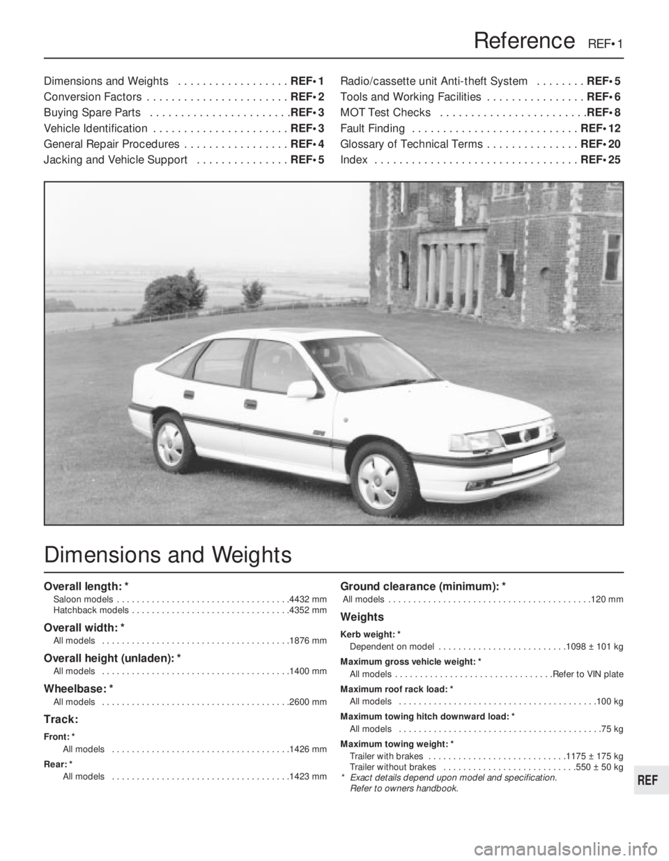
Overall length: *
Saloon models . . . . . . . . . . . . . . . . . . . . . . . . . . . . . . . . . . .4432 mm
Hatchback models . . . . . . . . . . . . . . . . . . . . . . . . . . . . . . . .4352 mm
Overall width: *
All models . . . . . . . . . . . . . . . . . . . . . . . . . . . . . . . . . . . . . .1876 mm
Overall height (unladen): *
All models . . . . . . . . . . . . . . . . . . . . . . . . . . . . . . . . . . . . . .1400 mm
Wheelbase: *
All models . . . . . . . . . . . . . . . . . . . . . . . . . . . . . . . . . . . . . .2600 mm
Track:
Front: *
All models . . . . . . . . . . . . . . . . . . . . . . . . . . . . . . . . . . . .1426 mm
Rear: *
All models . . . . . . . . . . . . . . . . . . . . . . . . . . . . . . . . . . . .1423 mm
Ground clearance (minimum): *
All models . . . . . . . . . . . . . . . . . . . . . . . . . . . . . . . . . . . . . . . . .120 mm
Weights
Kerb weight: *
Dependent on model . . . . . . . . . . . . . . . . . . . . . . . . . .1098 ± 101 kg
Maximum gross vehicle weight: *
All models . . . . . . . . . . . . . . . . . . . . . . . . . . . . . . . .Refer to VIN plate
Maximum roof rack load: *
All models . . . . . . . . . . . . . . . . . . . . . . . . . . . . . . . . . . . . . . . .100 kg
Maximum towing hitch downward load: *
All models . . . . . . . . . . . . . . . . . . . . . . . . . . . . . . . . . . . . . . . . .75 kg
Maximum towing weight: *
Trailer with brakes . . . . . . . . . . . . . . . . . . . . . . . . . . . .1175 ± 175 kg
Trailer without brakes . . . . . . . . . . . . . . . . . . . . . . . . . . .550 ± 50 kg
* Exact details depend upon model and specification.
Refer to owners handbook.
Dimensions and Weights . . . . . . . . . . . . . . . . . .REF•1
Conversion Factors . . . . . . . . . . . . . . . . . . . . . . .REF•2
Buying Spare Parts . . . . . . . . . . . . . . . . . . . . . . .REF•3
Vehicle Identification . . . . . . . . . . . . . . . . . . . . . .REF•3
General Repair Procedures . . . . . . . . . . . . . . . . .REF•4
Jacking and Vehicle Support . . . . . . . . . . . . . . .REF•5Radio/cassette unit Anti-theft System . . . . . . . .REF•5
Tools and Working Facilities . . . . . . . . . . . . . . . .REF•6
MOT Test Checks . . . . . . . . . . . . . . . . . . . . . . . .REF•8
Fault Finding . . . . . . . . . . . . . . . . . . . . . . . . . . .REF•12
Glossary of Technical Terms . . . . . . . . . . . . . . .REF•20
Index . . . . . . . . . . . . . . . . . . . . . . . . . . . . . . . . .REF•25
Reference REF•1
Dimensions and Weights
Page 242 of 525
Spare parts are available from many
sources, for example: Vauxhall dealers, other
garages and accessory shops, and motor
factors. Our advice regarding spare part
sources is as follows.
Officially appointed Vauxhall
dealers
This is the best source of parts that are
peculiar to your car and are otherwise not
generally available (e.g. complete cylinder
heads, transmission components, badges,
interior trim, etc.). It is also the only place at
which you should buy parts if your vehicle is
still under warranty -use of non-Vauxhall
components may invalidate the warranty. To
be sure of obtaining the correct parts it willalways be necessary to give the storeman
your car’s vehicle identification number, and if
possible, to take the “old” parts along for
positive identification. Remember that many
parts are available on a factory exchange
scheme -any parts returned should always be
clean! It obviously makes good sense to go
straight to the specialists on your car for this
type of part for they are best equipped to
supply you.
Other garages and accessory
shops
These are often very good places to buy
materials and components needed for the
maintenance of your car (e.g. oil filters, spark
plugs, bulbs, drivebelts, oils and greases,touch-up paint, filler paste, etc.). They also
sell general accessories, usually have
convenient opening hours, charge lower
prices and can often be found not far from
home.
Motor factors
Good factors will stock all the more
important components that wear out
relatively quickly (e.g. clutch components,
pistons, valves, exhaust systems, brake
cylinders/pipes/hoses/seals/shoes and pads,
etc.). Motor factors will often provide new or
reconditioned components on a part
exchange basis -this can save considerable
amount of money.
Modifications are a continuing and
unpublished process in vehicle manufacture,
quite apart from major model changes. Spare
parts manuals and lists are compiled upon a
numerical basis, the individual vehicle
numbers being essential to correct identifi-
cation of the component required.
When ordering spare parts, always give as
much information as possible. Quote the car
model, year of manufacture and vehicle iden-
tification and/or engine numbers as
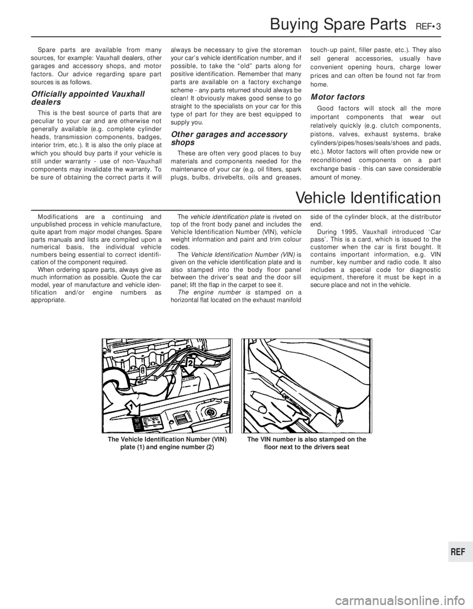
appropriate.The vehicle identification plate is riveted on
top of the front body panel and includes the
Vehicle Identification Number (VIN), vehicle
weight information and paint and trim colour
codes.
The Vehicle Identification Number (VIN) is
given on the vehicle identification plate and is
also stamped into the body floor panel
between the driver’s seat and the door sill
panel; lift the flap in the carpet to see it.
The engine number is stamped on a
horizontal flat located on the exhaust manifoldside of the cylinder block, at the distributor
end.
During 1995, Vauxhall introduced ‘Car
pass’. This is a card, which is issued to the
customer when the car is first bought. It
contains important information, e.g. VIN
number, key number and radio code. It also
includes a special code for diagnostic
equipment, therefore it must be kept in a
secure place and not in the vehicle.
Buying Spare Parts REF•3
The VIN number is also stamped on the
floor next to the drivers seatThe Vehicle Identification Number (VIN)
plate (1) and engine number (2)
REF
Vehicle Identification
Page 244 of 525
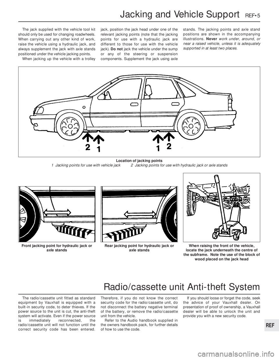
The jack supplied with the vehicle tool kit
should only be used for changing roadwheels.
When carrying out any other kind of work,
raise the vehicle using a hydraulic jack, and
always supplement the jack with axle stands
positioned under the vehicle jacking points.
When jacking up the vehicle with a trolleyjack, position the jack head under one of the
relevant jacking points (note that the jacking
points for use with a hydraulic jack are
different to those for use with the vehicle
jack). Do not jack the vehicle under the sump
or any of the steering or suspension
components. Supplement the jack using axlestands. The jacking points and axle stand
positions are shown in the accompanying
illustrations. Never work under, around, or
near a raised vehicle, unless it is adequately
supported in at least two places.
The radio/cassette unit fitted as standard
equipment by Vauxhall is equipped with a
built-in security code, to deter thieves. If the
power source to the unit is cut, the anti-theft
system will activate. Even if the power source
is immediately reconnected, the
radio/cassette unit will not function until the
correct security code has been entered.Therefore, if you do not know the correct
security code for the radio/cassette unit, do
not disconnect the battery negative terminal
of the battery, or remove the radio/cassette
unit from the vehicle.
Refer to the Audio handbook supplied in
the owners handbook pack, for further details
of how to use the code.If you should loose or forget the code, seek
the advice of your Vauxhall dealer. On
presentation of proof of ownership, a Vauxhall
dealer will be able to unlock the unit and
provide you with a new security code.
Jacking and Vehicle Support REF•5
Rear jacking point for hydraulic jack or
axle standsWhen raising the front of the vehicle,
locate the jack underneath the centre of
the subframe. Note the use of the block of
wood placed on the jack headFront jacking point for hydraulic jack or
axle stands
Location of jacking points
1 Jacking points for use with vehicle jack 2 Jacking points for use with hydraulic jack or axle stands
REF
Radio/cassette unit Anti-theft System
Page 266 of 525
Pierburg 2E3 carburettor- 4A•5
Piston rings- 2A•30
Piston/connecting rod- 2A•29
Plastic components- 11•3
Potentiometer- 4B•12, 4B•16
Power steering fluid - 0•14, 0•17, 1•2, 1•12
Power steering pump- 10•22
Power steering system bleeding- 10•22
Punctures- 0•8
RRadiator- 3•3
Radiator cooling fan- 3•5
Radiator grille- 11•12
Radio/cassette anti theft system- REF•5
Radio/cassette player- 12•18
Rear hub- 10•10, 10•15
Rear lamps- 12•11
Rear suspension assembly- 10•15
Relays- 12•3
Release bearing (clutch)- 6•6
Repair procedures- REF •4
Respraying- 11•2
Reversing lamp switch- 7A•6
Road test- 1•13
Roll bars- 10•8, 10•13, 10•17
Routine maintenance - 1•1 et seq
SSafety first!- 0•5
Scratches- 11•2
Seat belts- 11•21
Seats- 11•20, 11•22
Seats heated- 12•6
Selector cable (automatics)- 7B•4
Selector lever- 7B•4
Sender unit fuel level- 4A•4, 4B•8
Sender units (temperature gauge)- 3•6
Servicing - see Routine maintenance
Servo unit (braking system)- 9•15
Shock absorber- 10•11
Shoes (brake)- 9•6
Short-circuit finding- 12•2
Spark plugs- 1•3, 1•14, 1•16
Speakers- 12•17
Speedometer cable- 12•18
Speedometer drive- 7A•6
Starter inhibitor switch- 7B•3
Starter motor- 5•8
Starting problems- 0•6
Steering wheel alignment- 10•1, 10•24
Steering- 10•1 et seq
camber - 10•1 10•24
castor - 10•1, 10•24
column - 10•18
damper - 10•21
fault diagnosis - REF•12, REF•17gear - 10•21
power steering system bleeding - 10•22
power steering fluid - 0•17, 1•2
power steering pump - 10•22
shaft rubber coupling - 10•18
tie-rod end - 10•23
toe setting - 10•1, 10•24
wheel - 10•17
wheel bearing - 10•4, 10•9, 10•14
wheel with airbag - 12•20
Stub axle- 10•13
Subframe- 10•5
Sump- 2A•27, 2B•9
Sunroof- 11•13
Sunroof motor- 12•18
Sunroof switch- 12•5
Suspension- 10•1 et seq
anti-roll bars - 10•8, 10•13, 10•17
assembly (rear) - 10•15
coil spring (rear) - 10•12, 10•15
fault diagnosis - REF•12, REF•17
level control system - 10•14
lower arm (front) - 10•7
rear hub - 10•10, 10•15
shock absorber - 10•11
strut (front) - 10•6
stub axle - 10•13
sub frame - 10•5
trailing arms - 10•12, 10•16
wheel bearing - 10•4, 10•9, 10•14
Suspension/steering checks- 1•10
Switches:
brake lamp - 12•5
cooling fan - 3•6
courtesy lamp - 12•5
electric door mirror - 12•5
handbrake warning lamp - 12•5
hazard warning - 12•4
heater blower motor - 12•4
ignition - 12•3
indicator - 12•4
kickdown - 7B•3
lights - 12•4
luggage compartment - 12•5
oil pressure warning lamp - 12•5
push button - 12•4
reversing lamp - 7A•6
starter inhibitor - 7B•3
sunroof - 12•5
TTailgate- 11•5
Temperature gauge sender- 3•6
Temperature sensor (automatics)- 7B•5
Thermostat- 3•4
Throttle cable- 4A•5, 4B•9
Throttle pedal- 4A•5Tie-rod end- 10•23
Timing- 5•2, 5•13
Timing belt- 1•16, 2A•13, 2B•3, 2B•6
Toe setting- 10•1, 10•24
Tools and working facilities- REF•4, REF•6,
REF•7
Towing- 0•9
Trim panel (door)- 11•6
Tyre checks- 0•16, 0•17
Tyre pressures- 0•17
UUnderbody- 11•1
Underbody views- 1•7
Underbonnet views- 0•10, 1•5
Upholstery and carpets- 11•2
VVacuum servo unit (braking system)- 9•15
Valve lifters- 2A•24, 2B•9
Valves- 2A•5, 2B•2
Vehicle identification numbers- REF•3
Ventilation system- 3•1 et seq
Vents- 3•8
WWasher fluid- 0•13, 1•2
Washers- 12•13, 12•15
Water pump- 3•4
Weekly checks- 0•10et seq
Wheelalignment- 10•1, 10•24
Wheel arch liners- 11•12
Wheel bearing- 10•4, 10•9, 10•14
Wheel changing- 0•8
Wheel cylinder- 9•11
Window glass- 11•9
Window regulator- 11•10
Windscreen- 11•9, 11•12
Wiper blades- 0•15, 12•13
Wiper motors- 12•14
Wiring diagrams- 12•22 et seq
Index REF•27
REF