engine coolant OPEL CALIBRA 1988 Service Owner's Manual
[x] Cancel search | Manufacturer: OPEL, Model Year: 1988, Model line: CALIBRA, Model: OPEL CALIBRA 1988Pages: 525, PDF Size: 58.26 MB
Page 164 of 525
regulator vacuum pipe should be routed over
the top of the camshaft cover breather hoses.
21On models with the Multec system note
also the following:
a)Fit the new diaphragm so that it locates in
the throttle body groove.
b)Ensure that the spring and spring seat are
correctly engaged with each other and
with the diaphragm and regulator cover.
Then press the cover over its locating
dowels and hold it in place while the
screws are tightened.
c)Tighten the screws carefully to the
specified torque wrench setting.
22On completion, check the regulator for
leaks, pressurising the system by switching
the ignition on and off several times, before
the engine is started.
22Idle speed adjuster - removal
and refitting
3
Note:Idle speed adjustment on models fitted
with Multec systems, is not possible, as it is
controlled by the ECU. Refer to Section 1.
Removal
SOHC models (except Multec system)
1Disconnect the battery negative lead.
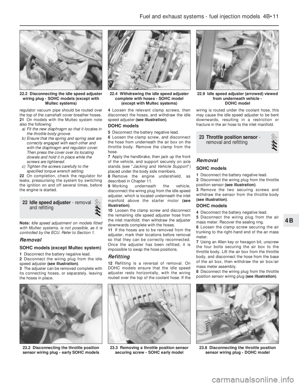
2Disconnect the wiring plug from the idle
speed adjuster (see illustration).
3The adjuster can be removed complete with
its connecting hoses, or separately, leaving
the hoses in place.4Loosen the relevant clamp screws, then
disconnect the hoses, and withdraw the idle
speed adjuster (see illustration).
DOHC models
5Disconnect the battery negative lead.
6Loosen the clamp screw, and disconnect
the hose from underneath the air box on the
throttle body. Remove the clamp from the
hose.
7Apply the handbrake, then jack up the front
of the vehicle, and support securely on axle
stands (see “Jacking and Vehicle Support”)
placed under the body side members.
8Remove the engine undershield, as
described in Chapter 11.
9Working underneath the vehicle,
disconnect the wiring plug from the idle speed
adjuster, which is located underneath the inlet
manifold above the starter motor (see
illustration).
10Loosen the clamp screw and disconnect
the remaining idle speed adjuster hose from
the inlet manifold, then withdraw the adjuster
downwards complete with the hoses.
11If the hoses are to be removed from the
adjuster, mark their locations before removal
so that they can be correctly reconnected.
Once the adjuster has been refitted, it is
impossible to swap the hose positions.
Refitting
12Refitting is a reversal of removal. On
DOHC models ensure that the idle speed
adjuster rests horizontally, with the wiring
routed over the top of the coolant hose. If thewiring is routed under the coolant hose, this
may cause the idle speed adjuster to be bent
downwards, resulting in a restriction or
fracture in the air hose to the inlet manifold.
23Throttle position sensor -
removal and refitting
3
Removal
SOHC models
1Disconnect the battery negative lead.
2Disconnect the wiring plug from the throttle
position sensor (see illustration).
3Remove the two securing screws and
withdraw the sensor from the throttle body
(see illustration).
DOHC models
4Disconnect the battery negative lead.
5Disconnect the wiring plug from the air
mass meter. Recover the sealing ring.
6Loosen the clamp screw securing the air
trunking to the right-hand end of the air mass
meter.
7Using an Allen key or hexagon bit, unscrew
the four bolts securing the air box to the
throttle body. Lift the air box from the throttle
body, and disconnect the hose from the base
of the air box, then withdraw the air box/air
mass meter assembly.
8Disconnect the wiring plug from the throttle
position sensor wiring plug (see illustration).
Fuel and exhaust systems - fuel injection models 4B•11
22.9 Idle speed adjuster (arrowed) viewed
from underneath vehicle -
DOHC model
23.8 Disconnecting the throttle position
sensor wiring plug - DOHC model23.3 Removing a throttle position sensor
securing screw - SOHC early model23.2 Disconnecting the throttle position
sensor wiring plug - early SOHC models
22.4 Withdrawing the idle speed adjuster
complete with hoses - SOHC model
(except with Multec systems)22.2 Disconnecting the idle speed adjuster
wiring plug - SOHC models (except with
Multec systems)
4B
Page 167 of 525

23Disconnect the wiring harness housing
from the fuel injectors, and move it to one
side, taking care not to strain the wiring. Pull
up on the wiring harness housing, and
compress the wiring plug retaining clips to
release the housing from the injectors.
24Unscrew and remove the two fuel rail
securing nuts, and withdraw the fuel rail
complete with fuel injectors from the inlet
manifold. Note the position of the earth leads
on the fuel rail securing studs (see
illustration).
25To remove an injector from the fuel rail,
prise out the metal securing clip using a
screwdriver, then pull the injector from the fuel
rail
Refitting
26Refitting is as described in paragraphs 8
to 11 inclusive.
29Fuel injector (Multec system)
- removal and refitting
3
Removal
1Depressurise the fuel system (see Sec
tion 8).
2Remove the air box (see Section 5).
3Disconnect the battery earth lead.
4Disconnect the wiring plug from the fuel
injector (see illustration).
5Undo the Torx-type screw (size TX 20)
securing the fuel injector retainer to the top ofthe throttle body, remove the retainer and lift
out the injector (see illustration). Remove
and discard the injector sealing rings.
Refitting
6Refitting is the reverse of the removal
procedure, noting the following points.
a)Always renew both sealing rings; apply a
smear of grease to each to ease injector
refitting (see illustration).
b)Refit the injector so that its wiring
terminals point to the rear of the vehicle;
locate the edge of the retainer securely in
the groove at the top of the injector.
c)Apply a few drops of a thread-locking
compound to the screw threads, then
tighten it carefully to the specified torque
wrench setting.
d)Switch on the ignition and check carefully
for signs of fuel leaks; if any signs of
leakage are detected, the problem must
be rectified before the engine is started.
30Fuel injector (Multec system)
- testing
3
1A simple test of the injector’s windings is
possible for those who have a multi-meter of
sufficient sensitivity. First disconnect the
injector wiring plug as described in Section 29,
then connect the meter (set to the appropriate
resistance scale) across the injector’s
terminals and note the reading obtained.
2On C18 NZ engines, the reading should be
within the specified tolerance; similar results
can be expected on C16NZ, C16NZ2, and
X16 SZ engines.
3If the reading differs significantly from the
specified value, indicating either shorted or
open circuit windings, the injector must be
renewed.
4Note that this is only a test of the injector’s
electrical condition; it does not test its spray
pattern or performance. If the injector is
thought to be faulty it is always worth trying a
well known injector-cleaning treatment. If this
fails, the vehicle must be taken to a Vauxhall
dealer for full testing on the special test
equipment.
31Throttle body (except Multec
system) - removal and refitting
3
Note:Refer to Section 2 before proceeding. A
new throttle body gasket must be used on
refitting
SOHC
Removal
1Disconnect the battery negative lead.
2Loosen the clamp screws securing the air
trunking to the throttle body and the airflow
meter, then withdraw the air trunking.
3Loosen the clamp screw, and disconnect
the idle speed adjuster hose from the throttle
body.
4Disconnect the camshaft cover breather
hose from the throttle body.
5Disconnect the coolant hoses from the
throttle body. Be prepared for coolant
spillage, and clamp or plug the open ends of
the hoses, to prevent further coolant loss.
6Disconnect the wiring plug from the throttle
position sensor.
7Release the securing clip, then disconnect
the throttle cable end balljoint from the throttle
valve lever.
8Slide the throttle cable grommet from the
bracket on the inlet manifold, then unhook the
throttle return spring from the bracket (see
illustration).
9Make a final check to ensure that all relevant
hoses and wires have been disconnected and
moved clear of the throttle body.
4B•14Fuel and exhaust systems - fuel injection models
28.24 Earth leads secured to fuel rail stud
(arrowed) - DOHC model29.5 Unscrewing the injector retainer Torx
screw
31.8 Unhook the throttle return spring
from the bracket on the inlet manifold
(inlet manifold removed for clarity)29.6 Renew injector sealing rings
(arrowed)
29.4 Disconnecting the fuel injector wiring
plug - Multec systems
Page 170 of 525

Refitting
5Refitting is a reversal of the removal
procedure, ensuring that the wiring plugs are
correctly reconnected and that the unit is
located securely.
36Knock sensor and module
(X16 SZ models) - removal
and refitting
3
Removal
1The knock sensor fitted to the X16 SZ
engine is located on the cylinder block below
the inlet manifold, between cylinders 2 and 3.
2Disconnect the battery negative lead.
3Remove the wiring and unscrew the unit
from the block.
4The module and control unit are located on
the left-hand side of the engine compartment
behind the battery. To remove, disconnect the
wiring multiplug and remove the retaining
bolts (see illustration).
5There is no provision for testing the knock
sensor or module without dedicated Vauxhall
test equipment. Check for external damage
and replace if necessary.
Refitting
6Refitting is a reversal of the removal
procedure, ensuring that the wiring plugs are
correctly reconnected and that the units are
located securely.
37Knock sensor (Simtec
system) - removal and refitting
3
Removal
1Disconnect the battery negative lead.
2Disconnect wiring harness plug, from inlet
air temperature sensor and wiring harness
plug, from hot mass air flow meter.
3Remove crankcase ventilation hoses.
4Remove coolant hoses from air inlet hoses,
hot film mass air flow meter complete with air
inlet hoses, from upper part of air cleaner and
throttle body.5Press retaining clip for 1st and 4th cylinder
injectors in plug strip (with screwdriver)
towards fuel distributor pipe - lifting plug strip
at the same time. On the underside of the plug
strip there are a total of 6 plug connections, 4
of which are for the injectors.
6Disconnect wiring harness plug for knock
sensor from the plug strip.
7Connect a 1 metre length of separate cable
to knock sensor wiring harness plug (note
routing).
8Remove knock sensor from cylinder block
(see illustration).
9Disconnect knock sensor cable from
separately attached cable, separate cable
remains in engine compartment.
Refitting
10Refitting is a reversal of removal, but note
the following.
11Before refitting ensure that the sensor is
spotlessly clean. Clean the entire contact
surface of the sensor must lie directly on the
cylinder block. Do not use any form of
washers.
12Carefully refit sensor into the block.
Tighten to the correct torque.
13Guide knock sensor cable between ridges
on inlet manifold using separate cable -
ensure correct routing.
14Remove the cable.
15Insert the wiring harness plug for the
knock sensor, into the plug strip.
16Correctly align the spring clips for theinjectors as they may prevent engagement of
the plug strip. Correct contact between the
plug strip and the injector is essential.
17When connecting plug strip, an audible
‘click’ should be heard.
18Ensure that hoses are in good condition
and installed securely with the two clamps.
38Inlet manifold (SOHC without
Multec) - removal and refitting
3
Note:Refer to warning in Section 2, before
proceeding. Use a new gaskets when refitting.
Removal
1Disconnect the battery negative lead.
2Remove the idle speed adjuster and its
hoses, referring to Section 22, if necessary.
3Release the securing clip, then disconnect
the throttle cable and balljoint from the throttle
valve lever. Slide the throttle cable grommet
from the bracket on the inlet manifold, and
move the throttle cable to one side out of the
way.
4Loosen the clamp screw and disconnect
the air trunking from the throttle body.
5Unscrew the union nut and disconnect the
brake servo vacuum hose from the inlet
manifold(see illustration).
6Disconnect the camshaft cover breather
hose from the throttle body.
7Disconnect the coolant hoses from the
throttle body. Be prepared for coolant
spillage, and clamp or plug the open ends of
the hoses, to prevent further coolant loss.
8Disconnect the wiring plug from the throttle
position sensor.
9Disconnect the vacuum pipe from the top
of the fuel pressure regulator.
10Disconnect the wiring harness housing
from the fuel injectors and move it to one side,
taking care not to strain the wiring. Pull up on
the wiring harness housing, and compress the
wiring plug retaining clips to release the
harness housing from the injectors.
11Disconnect the fuel hoses from the fuel
rail. Be prepared for fuel spillage, and take
adequate fire precautions. Clamp or plug the
open ends of the hoses, to prevent dirt
ingress and further fuel leakage.
Fuel and exhaust systems - fuel injection models 4B•17
38.5 Disconnecting the brake servo
vacuum hose -
SOHC models37.8 Knock sensor and wiring
(Simtec system)
1 Sensor2 Securing bolt
36.4 Knock sensor and module (X16 SZ models)
1 Sensor2 Module3 Sensor securing bolt
4B
Page 172 of 525
1
Chapter 1
Routine maintenance and servicing
Air cleaner element - renewal . . . . . . . . . . . . . . . . . . . . . . . . . . . . . . .27
Air inlet temperature control check . . . . . . . . . . . . . . . . . . . . . . . . . .28
Alternator V-belt check . . . . . . . . . . . . . . . . . . . . . . . . . . . . . . . . . . . .22
Automatic transmission check . . . . . . . . . . . . . . . . . . . . . . . . . . . . . .34
Automatic transmission fluid level check . . . . . . . . . . . . . . . . . . . . . . .7
Automatic transmission fluid renewal . . . . . . . . . . . . . . . . . . . . . . . . .38
Bodywork check . . . . . . . . . . . . . . . . . . . . . . . . . . . . . . . . . . . . . . . . .20
Brake fluid renewal . . . . . . . . . . . . . . . . . . . . . . . . . . . . . . . . . . . . . . .14
Brake pad check . . . . . . . . . . . . . . . . . . . . . . . . . . . . . . . . . . . . . . . . .15
Brake shoe check . . . . . . . . . . . . . . . . . . . . . . . . . . . . . . . . . . . . . . . .35
Clutch cable check . . . . . . . . . . . . . . . . . . . . . . . . . . . . . . . . . . . . . . .32
Coolant renewal . . . . . . . . . . . . . . . . . . . . . . . . . . . . . . . . . . . . . . . . .26
Distributor and HT lead check . . . . . . . . . . . . . . . . . . . . . . . . . . . . . .31
Door lock key battery - replacement . . . . . . . . . . . . . . . . . . . . . . . . .24
Driveshaft gaiter check . . . . . . . . . . . . . . . . . . . . . . . . . . . . . . . . . . . . .6
Engine oil and filter - renewal . . . . . . . . . . . . . . . . . . . . . . . . . . . . . . . .3
Exhaust system check . . . . . . . . . . . . . . . . . . . . . . . . . . . . . . . . . . . .11
Fuel filter renewal . . . . . . . . . . . . . . . . . . . . . . . . . . . . . . . . . . . . . . . .29
Handbrake linkage check . . . . . . . . . . . . . . . . . . . . . . . . . . . . . . . . . .16Headlamp alignment . . . . . . . . . . . . . . . . . . . . . . . . . . . . . . . . . . . . . .23
Hose and fluid leak check . . . . . . . . . . . . . . . . . . . . . . . . . . . . . . . . . .4
Idle speed and mixture - adjustment . . . . . . . . . . . . . . . . . . . . . . . . . .9
Ignition timing . . . . . . . . . . . . . . . . . . . . . . . . . . . . . . . . . . . . . . . . . . .13
Intensive maintenance . . . . . . . . . . . . . . . . . . . . . . . . . . . . . . . . . . . . .2
Introduction . . . . . . . . . . . . . . . . . . . . . . . . . . . . . . . . . . . . . . . . . . . . .1
Lock and hinge check . . . . . . . . . . . . . . . . . . . . . . . . . . . . . . . . . . . .21
Manual transmission fluid check . . . . . . . . . . . . . . . . . . . . . . . . . . . .33
Power steering fluid check . . . . . . . . . . . . . . . . . . . . . . . . . . . . . . . . .17
Power steering pump drivebelt check . . . . . . . . . . . . . . . . . . . . . . . .18
Radiator inspection and cleaning . . . . . . . . . . . . . . . . . . . . . . . . . . . . .8
Rear suspension level control system check . . . . . . . . . . . . . . . . . . .19
Road test . . . . . . . . . . . . . . . . . . . . . . . . . . . . . . . . . . . . . . . . . . . . . .25
Spark plug renewal (SOHC) . . . . . . . . . . . . . . . . . . . . . . . . . . . . . . . .30
Spark plug renewal (DOHC) . . . . . . . . . . . . . . . . . . . . . . . . . . . . . . . .37
Steering and suspension check . . . . . . . . . . . . . . . . . . . . . . . . . . . . . .5
Throttle linkage maintenance . . . . . . . . . . . . . . . . . . . . . . . . . . . . . . .10
Timing belt renewal . . . . . . . . . . . . . . . . . . . . . . . . . . . . . . . . . . . . . . .36
Wiring check . . . . . . . . . . . . . . . . . . . . . . . . . . . . . . . . . . . . . . . . . . . .12
1•1
Contents
Easy,suitable for
novice with little
experienceFairly easy,suitable
for beginner with
some experienceFairly difficult,
suitable for competent
DIY mechanic
Difficult,suitable for
experienced DIY
mechanicVery difficult,
suitable for expert DIY
or professional
Degrees of difficulty
54321
Page 175 of 525
1•4Maintenance schedule
Every 250 miles (400 km) or weekly
MRefer to “Weekly checks”
Basic service, every 9000 miles
(15 000 km) or 12 months -
whichever comes sooner
Along with the items in “Weekly checks”, carry out the
following:
MRenew the engine oil and oil filter (Section 3).
MCheck all hoses and other components for fluid
leaks (Section 4).
MCheck the steering and suspension components
(Section 5).
MCheck the condition of the driveshaft rubber
gaiters (Section 6).
MCheck the automatic transmission fluid level (if
applicable), (Section 7).
MCheck the radiator for blockage (e.g. dead insects)
and clean as necessary (Section 8).
MCheck and adjust the idle speed and mixture (if
applicable), (Section 9).
MCheck the throttle linkage and lubricate if
necessary (Section 10).
MCheck the exhaust system for corrosion, leaks and
security (Section 11).
MCheck all wiring for condition and security
(Section 12).
MCheck and adjust the ignition timing (if applicable),
(Section 13).
MRenew the brake fluid (Section 14).
MCheck the brake pad friction material for wear
(Section 15).
MCheck the handbrake linkage (Section 16).
MCheck the power steering fluid level (if applicable),
(Section 17).
MCheck the power steering pump drivebelt (if
applicable), (Section 18).
MCheck the rear suspension level control system
height, if fitted (Section 19).
MCheck the bodywork (Section 20).
MLubricate all locks and hinges (Section 21).
MCheck the alternator V-belt (Section 22).
MCheck the headlamp alignment (Section 23).
MReplace battery in the door-lock key (if applicable),
(Section 24).
MCarry out a road test (Section 25).
Note: Vauxhall specify that an Exhaust Emissions Test should be
carried out at least annually. However, this requires special
equipment, and is performed as part of the MOT test (refer to the
end of the manual).
Full service, every 18 000 miles
(30 000 km) or 24 months -
whichever comes sooner
Along with the ‘basic service’, carry out the following:
MRenew the coolant (Section 26).
MRenew the air cleaner element (Section 27).
MCheck the operation of the air cleaner air inlet
temperature control (carburettor models only),
(Section 28).
MRenew the fuel filter (Section 29).
MRenew the spark plugs (SOHC only), (Section 30) *.
MInspect and clean the distributor cap and HT leads
(Section 31).
MCheck the clutch cable adjustment (Section 32).
MCheck the manual transmission oil level (Section 33).
MCheck the automatic transmission (Section 34).
MCheck the brake drum shoe for wear (Section 35).
Major service, every 36 000 miles
(60 000 km) or 48 months -
whichever comes sooner
Along with the ‘full service’, carry out the following:
MRenew timing belt (Section 36).
MRenew the spark plugs (DOHC models only),
(Section 37).
MRenew automatic transmission fluid (Section 38) *.
* Note: If a vehicle is used for heavy-duty work (e.g. taxi work,
caravan/trailer towing, mostly short-distance, stop-start city driving)
the fluid must be changed every 36 months or 27 000 miles (45 000
km), whichever occurs first.
Page 176 of 525
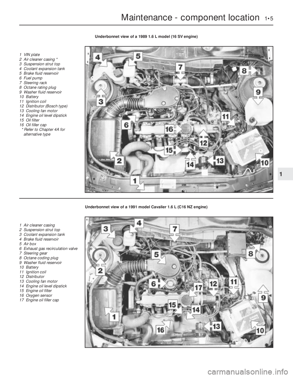
Maintenance - component location 1•5
1
Underbonnet view of a 1989 1.6 L model (16 SV engine)
1 VIN plate
2 Air cleaner casing *
3 Suspension strut top
4 Coolant expansion tank
5 Brake fluid reservoir
6 Fuel pump
7 Steering rack
8 Octane rating plug
9 Washer fluid reservoir
10 Battery
11 Ignition coil
12 Distributor (Bosch type)
13 Cooling fan motor
14 Engine oil level dipstick
15 Oil filter
16 Oil filler cap
* Refer to Chapter 4A for
alternative type
Underbonnet view of a 1991 model Cavalier 1.6 L (C16 NZ engine)
1 Air cleaner casing
2 Suspension strut top
3 Coolant expansion tank
4 Brake fluid reservoir
5 Air box
6 Exhaust gas recirculation valve
7 Steering gear
8 Octane coding plug
9 Washer fluid reservoir
10 Battery
11 Ignition coil
12 Distributor
13 Cooling fan motor
14 Engine oil level dipstick
15 Engine oil filter
16 Oxygen sensor
17 Engine oil filler cap
Page 177 of 525
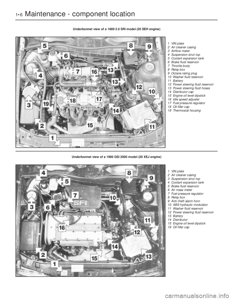
1•6Maintenance - component location
Underbonnet view of a 1989 2.0 SRi model (20 SEH engine)
1 VIN plate
2 Air cleaner casing
3 Airflow meter
4 Suspension strut top
5 Coolant expansion tank
6 Brake fluid reservoir
7 Throttle body
8 Relay box
9 Octane rating plug
10 Washer fluid reservoir
11 Battery
12 Power steering fluid reservoir
13 Power steering fluid hoses
14 Distributor cap
15 Engine oil level dipstick
16 Idle speed adjuster
17 Fuel pressure regulator
18 Oil filler cap
19 Thermostat housing
Underbonnet view of a 1990 GSi 2000 model (20 XEJ engine)
1 VIN plate
2 Air cleaner casing
3 Suspension strut top
4 Coolant expansion tank
5 Brake fluid reservoir
6 Air mass meter
7 Fuel pressure regulator
8 Relay box
9 Anti-theft alarm horn
10 ABS hydraulic modulator
11 Washer fluid reservoir
12 Power steering fluid reservoir
13 Battery
14 Distributor
15 Engine oil level dipstick
16 Oil filler cap
Page 184 of 525
tighten the mounting nuts and bolts. On no
account lever at the free end of the alternator,
as serious internal damage could be caused.
3For details of replacement, see Chapter 5.
23Headlamp alignment
2
Refer to Chapter 12 for details.
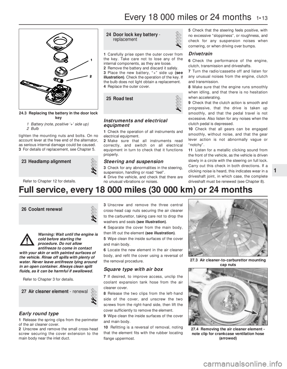
24Door lock key battery -
replacement
1
1Carefully prise open the outer cover from
the key. Take care not to lose any of the
internal components, as they are loose.
2Remove the battery and discard it safely.
3Place the new battery, “+” side up (see
illustration). Check the operation of the key. If
the bulb does not light obtain a replacement.
4Replace the outer cover.
25Road test
1
Instruments and electrical
equipment
1Check the operation of all instruments and
electrical equipment.
2Make sure that all instruments read
correctly, and switch on all electrical
equipment in turn to check that it functions
properly.
Steering and suspension
3Check for any abnormalities in the steering,
suspension, handling or road “feel”.
4Drive the vehicle, and check that there are
no unusual vibrations or noises.5Check that the steering feels positive, with
no excessive “sloppiness”, or roughness, and
check for any suspension noises when
cornering, or when driving over bumps.
Drivetrain
6Check the performance of the engine,
clutch, transmission and driveshafts.
7Turn the radio/cassette off and listen for
any unusual noises from the engine, clutch
and transmission.
8Make sure that the engine runs smoothly
when idling, and that there is no hesitation
when accelerating.
9Check that the clutch action is smooth and
progressive, that the drive is taken up
smoothly, and that the pedal travel is not
excessive. Also listen for any noises when the
clutch pedal is depressed.
10Check that all gears can be engaged
smoothly, without noise, and that the gear
lever action is not abnormally vague or
“notchy”.
11Listen for a metallic clicking sound from
the front of the vehicle, as the vehicle is driven
slowly in a circle with the steering on full lock.
Carry out this check in both directions. If a
clicking noise is heard, this indicates wear in a
driveshaft joint, in which case, the complete
driveshaft must be renewed (see Chapter 8).
26Coolant renewal
2
Refer to Chapter 3 for details.
27Air cleaner element - renewal
2
Early round type
1Release the spring clips from the perimeter
of the air cleaner cover.
2Unscrew and remove the small cross-head
screw securing the cover extension to the
main body near the inlet duct.3Unscrew and remove the three central
cross-head cap nuts securing the air cleaner
to the carburettor, taking care not to drop the
washers and seals (see illustration).
4Separate the cover from the main body,
then lift out the element (see illustration).
5Wipe clean the inside surfaces of the cover
and main body.
6Locate the new element in the air cleaner
body, and refit the cover using a reversal of
the removal procedure.
Square type with air box
7If desired, to improve access, unclip the
coolant expansion tank hose from the air
cleaner cover.
8Release the two clips from the left-hand
side of the cover, and unscrew the two
screws from the right-hand side, then lift the
cover sufficiently to remove the element.
9Wipe clean the inside surfaces of the cover
and main body.
10Refitting is a reversal of removal, noting
that the element fits with the rubber locating
flange uppermost.
Every 18 000 miles or 24 months 1•13
24.3 Replacing the battery in the door lock
key
1 Battery (note, positive ‘+’ side up)
2 Bulb
27.4 Removing the air cleaner element -
note clip for crankcase ventilation hose
(arrowed)
27.3 Air cleaner-to-carburettor mounting
cap nuts
1
Full service, every 18 000 miles (30 000 km) or 24 months
Warning: Wait until the engine is
cold before starting the
procedure. Do not allow
antifreeze to come in contact
with your skin or with painted surfaces of
the vehicle. Rinse off spills with plenty of
water. Never leave antifreeze lying around
in an open container. Always clean spilt
fluids, as it can be harmful if swallowed.
Page 189 of 525
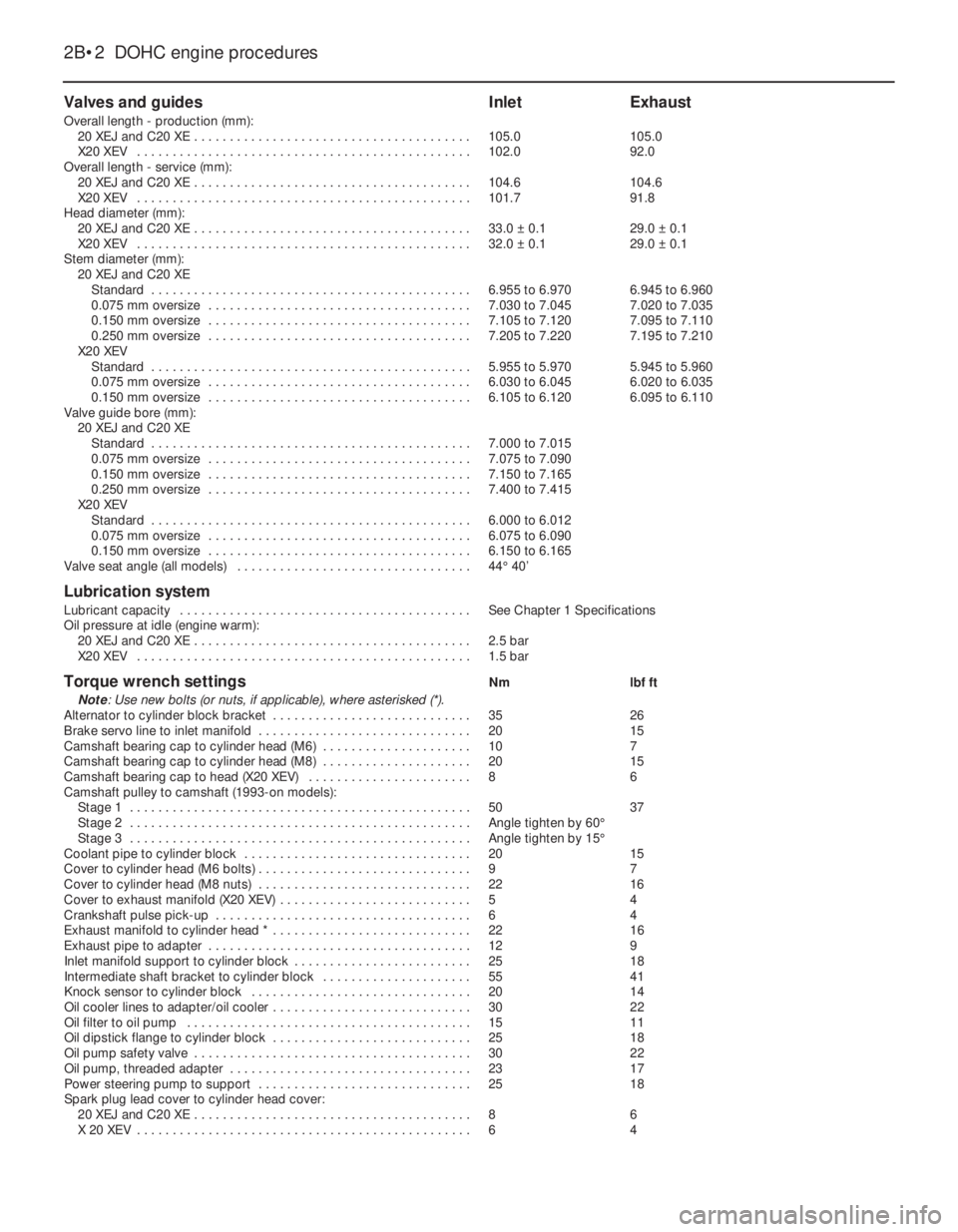
Valves and guidesInletExhaust
Overall length - production (mm):
20 XEJ and C20 XE . . . . . . . . . . . . . . . . . . . . . . . . . . . . . . . . . . . . . . .105.0105.0
X20 XEV . . . . . . . . . . . . . . . . . . . . . . . . . . . . . . . . . . . . . . . . . . . . . . .102.092.0
Overall length - service (mm):
20 XEJ and C20 XE . . . . . . . . . . . . . . . . . . . . . . . . . . . . . . . . . . . . . . .104.6104.6
X20 XEV . . . . . . . . . . . . . . . . . . . . . . . . . . . . . . . . . . . . . . . . . . . . . . .101.791.8
Head diameter (mm):
20 XEJ and C20 XE . . . . . . . . . . . . . . . . . . . . . . . . . . . . . . . . . . . . . . .33.0 ±0.129.0 ±0.1
X20 XEV . . . . . . . . . . . . . . . . . . . . . . . . . . . . . . . . . . . . . . . . . . . . . . .32.0 ±0.129.0 ±0.1
Stem diameter (mm):
20 XEJ and C20 XE
Standard . . . . . . . . . . . . . . . . . . . . . . . . . . . . . . . . . . . . . . . . . . . . .6.955 to 6.9706.945 to 6.960
0.075 mm oversize . . . . . . . . . . . . . . . . . . . . . . . . . . . . . . . . . . . . .7.030 to 7.0457.020 to 7.035
0.150 mm oversize . . . . . . . . . . . . . . . . . . . . . . . . . . . . . . . . . . . . .7.105 to 7.1207.095 to 7.110
0.250 mm oversize . . . . . . . . . . . . . . . . . . . . . . . . . . . . . . . . . . . . .7.205 to 7.2207.195 to 7.210
X20 XEV
Standard . . . . . . . . . . . . . . . . . . . . . . . . . . . . . . . . . . . . . . . . . . . . .5.955 to 5.9705.945 to 5.960
0.075 mm oversize . . . . . . . . . . . . . . . . . . . . . . . . . . . . . . . . . . . . .6.030 to 6.0456.020 to 6.035
0.150 mm oversize . . . . . . . . . . . . . . . . . . . . . . . . . . . . . . . . . . . . .6.105 to 6.1206.095 to 6.110
Valve guide bore (mm):
20 XEJ and C20 XE
Standard . . . . . . . . . . . . . . . . . . . . . . . . . . . . . . . . . . . . . . . . . . . . .7.000 to 7.015
0.075 mm oversize . . . . . . . . . . . . . . . . . . . . . . . . . . . . . . . . . . . . .7.075 to 7.090
0.150 mm oversize . . . . . . . . . . . . . . . . . . . . . . . . . . . . . . . . . . . . .7.150 to 7.165
0.250 mm oversize . . . . . . . . . . . . . . . . . . . . . . . . . . . . . . . . . . . . .7.400 to 7.415
X20 XEV
Standard . . . . . . . . . . . . . . . . . . . . . . . . . . . . . . . . . . . . . . . . . . . . .6.000 to 6.012
0.075 mm oversize . . . . . . . . . . . . . . . . . . . . . . . . . . . . . . . . . . . . .6.075 to 6.090
0.150 mm oversize . . . . . . . . . . . . . . . . . . . . . . . . . . . . . . . . . . . . .6.150 to 6.165
Valve seat angle (all models) . . . . . . . . . . . . . . . . . . . . . . . . . . . . . . . . .44°40’
Lubrication system
Lubricant capacity . . . . . . . . . . . . . . . . . . . . . . . . . . . . . . . . . . . . . . . . .See Chapter 1 Specifications
Oil pressure at idle (engine warm):
20 XEJ and C20 XE . . . . . . . . . . . . . . . . . . . . . . . . . . . . . . . . . . . . . . .2.5 bar
X20 XEV . . . . . . . . . . . . . . . . . . . . . . . . . . . . . . . . . . . . . . . . . . . . . . .1.5 bar
Torque wrench settingsNmlbf ft
Note: Use new bolts (or nuts, if applicable), where asterisked (*).
Alternator to cylinder block bracket . . . . . . . . . . . . . . . . . . . . . . . . . . . .3526
Brake servo line to inlet manifold . . . . . . . . . . . . . . . . . . . . . . . . . . . . . .2015
Camshaft bearing cap to cylinder head (M6) . . . . . . . . . . . . . . . . . . . . .107
Camshaft bearing cap to cylinder head (M8) . . . . . . . . . . . . . . . . . . . . .2015
Camshaft bearing cap to head (X20 XEV) . . . . . . . . . . . . . . . . . . . . . . .86
Camshaft pulley to camshaft (1993-on models):
Stage 1 . . . . . . . . . . . . . . . . . . . . . . . . . . . . . . . . . . . . . . . . . . . . . . . .5037
Stage 2 . . . . . . . . . . . . . . . . . . . . . . . . . . . . . . . . . . . . . . . . . . . . . . . .Angle tighten by 60°
Stage 3 . . . . . . . . . . . . . . . . . . . . . . . . . . . . . . . . . . . . . . . . . . . . . . . .Angle tighten by 15°
Coolant pipe to cylinder block . . . . . . . . . . . . . . . . . . . . . . . . . . . . . . . .2015
Cover to cylinder head (M6 bolts) . . . . . . . . . . . . . . . . . . . . . . . . . . . . . .97
Cover to cylinder head (M8 nuts) . . . . . . . . . . . . . . . . . . . . . . . . . . . . . .2216
Cover to exhaust manifold (X20 XEV) . . . . . . . . . . . . . . . . . . . . . . . . . . .54
Crankshaft pulse pick-up . . . . . . . . . . . . . . . . . . . . . . . . . . . . . . . . . . . .64
Exhaust manifold to cylinder head * . . . . . . . . . . . . . . . . . . . . . . . . . . . .2216
Exhaust pipe to adapter . . . . . . . . . . . . . . . . . . . . . . . . . . . . . . . . . . . . .129
Inlet manifold support to cylinder block . . . . . . . . . . . . . . . . . . . . . . . . .2518
Intermediate shaft bracket to cylinder block . . . . . . . . . . . . . . . . . . . . .5541
Knock sensor to cylinder block . . . . . . . . . . . . . . . . . . . . . . . . . . . . . . .2014
Oil cooler lines to adapter/oil cooler . . . . . . . . . . . . . . . . . . . . . . . . . . . .3022
Oil filter to oil pump . . . . . . . . . . . . . . . . . . . . . . . . . . . . . . . . . . . . . . . .1511
Oil dipstick flange to cylinder block . . . . . . . . . . . . . . . . . . . . . . . . . . . .2518
Oil pump safety valve . . . . . . . . . . . . . . . . . . . . . . . . . . . . . . . . . . . . . . .3022
Oil pump, threaded adapter . . . . . . . . . . . . . . . . . . . . . . . . . . . . . . . . . .2317
Power steering pump to support . . . . . . . . . . . . . . . . . . . . . . . . . . . . . .2518
Spark plug lead cover to cylinder head cover:
20 XEJ and C20 XE . . . . . . . . . . . . . . . . . . . . . . . . . . . . . . . . . . . . . . .86
X 20 XEV . . . . . . . . . . . . . . . . . . . . . . . . . . . . . . . . . . . . . . . . . . . . . . .64
2B•2DOHC engine procedures
Page 190 of 525
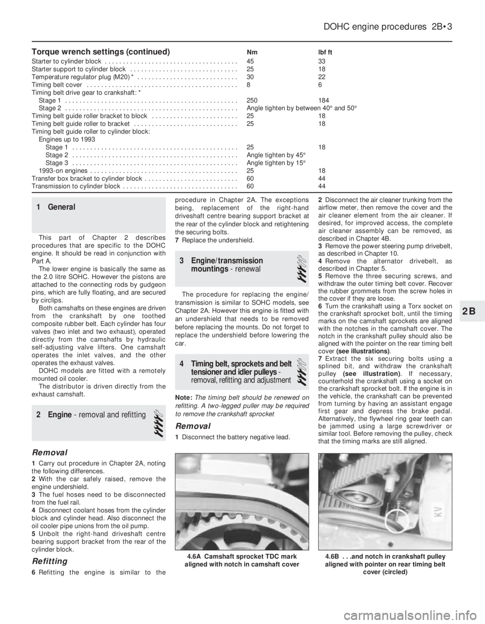
Torque wrench settings (continued)Nmlbf ft
Starter to cylinder block . . . . . . . . . . . . . . . . . . . . . . . . . . . . . . . . . . . . .4533
Starter support to cylinder block . . . . . . . . . . . . . . . . . . . . . . . . . . . . . .2518
Temperature regulator plug (M20) * . . . . . . . . . . . . . . . . . . . . . . . . . . . .3022
Timing belt cover . . . . . . . . . . . . . . . . . . . . . . . . . . . . . . . . . . . . . . . . . .86
Timing belt drive gear to crankshaft: *
Stage 1 . . . . . . . . . . . . . . . . . . . . . . . . . . . . . . . . . . . . . . . . . . . . . . . .250184
Stage 2 . . . . . . . . . . . . . . . . . . . . . . . . . . . . . . . . . . . . . . . . . . . . . . . .Angle tighten by between 40°and 50°
Timing belt guide roller bracket to block . . . . . . . . . . . . . . . . . . . . . . . .2518
Timing belt guide roller to bracket . . . . . . . . . . . . . . . . . . . . . . . . . . . . .2518
Timing belt guide roller to cylinder block:
Engines up to 1993
Stage 1 . . . . . . . . . . . . . . . . . . . . . . . . . . . . . . . . . . . . . . . . . . . . . .2518
Stage 2 . . . . . . . . . . . . . . . . . . . . . . . . . . . . . . . . . . . . . . . . . . . . . .Angle tighten by 45°
Stage 3 . . . . . . . . . . . . . . . . . . . . . . . . . . . . . . . . . . . . . . . . . . . . . .Angle tighten by 15°
1993-on engines . . . . . . . . . . . . . . . . . . . . . . . . . . . . . . . . . . . . . . . . .2518
Transfer box bracket to cylinder block . . . . . . . . . . . . . . . . . . . . . . . . . .6044
Transmission to cylinder block . . . . . . . . . . . . . . . . . . . . . . . . . . . . . . . .6044
1General
This part of Chapter 2 describes
procedures that are specific to the DOHC
engine. It should be read in conjunction with
Part A.
The lower engine is basically the same as
the 2.0 litre SOHC. However the pistons are
attached to the connecting rods by gudgeon
pins, which are fully floating, and are secured
by circlips.
Both camshafts on these engines are driven
from the crankshaft by one toothed
composite rubber belt. Each cylinder has four
valves (two inlet and two exhaust), operated
directly from the camshafts by hydraulic
self-adjusting valve lifters. One camshaft
operates the inlet valves, and the other
operates the exhaust valves.
DOHC models are fitted with a remotely
mounted oil cooler.
The distributor is driven directly from the
exhaust camshaft.
2Engine - removal and refitting
4
Removal
1Carry out procedure in Chapter 2A, noting
the following differences.
2With the car safely raised, remove the
engine undershield.
3The fuel hoses need to be disconnected
from the fuel rail.
4Disconnect coolant hoses from the cylinder
block and cylinder head. Also disconnect the
oil cooler pipe unions from the oil pump.
5Unbolt the right-hand driveshaft centre
bearing support bracket from the rear of the
cylinder block.
Refitting
6Refitting the engine is similar to theprocedure in Chapter 2A. The exceptions
being, replacement of the right-hand
driveshaft centre bearing support bracket at
the rear of the cylinder block and retightening
the securing bolts.
7Replace the undershield.
3Engine/transmission
mountings- renewal
3
The procedure for replacing the engine/
transmission is similar to SOHC models, see
Chapter 2A. However this engine is fitted with
an undershield that needs to be removed
before replacing the mounts. Do not forget to
replace the undershield before lowering the
car.
4Timing belt, sprockets and belt
tensioner and idler pulleys-
removal, refitting and adjustment
3
Note: The timing belt should be renewed on
refitting. A two-legged puller may be required
to remove the crankshaft sprocket
Removal
1Disconnect the battery negative lead.2Disconnect the air cleaner trunking from the
airflow meter, then remove the cover and the
air cleaner element from the air cleaner. If
desired, for improved access, the complete
air cleaner assembly can be removed, as
described in Chapter 4B.
3Remove the power steering pump drivebelt,
as described in Chapter 10.
4Remove the alternator drivebelt, as
described in Chapter 5.
5Remove the three securing screws, and
withdraw the outer timing belt cover. Recover
the rubber grommets from the screw holes in
the cover if they are loose.
6Turn the crankshaft using a Torx socket on
the crankshaft sprocket bolt, until the timing
marks on the camshaft sprockets are aligned
with the notches in the camshaft cover. The
notch in the crankshaft pulley should also be
aligned with the pointer on the rear timing belt
cover (see illustrations).
7Extract the six securing bolts using a
splined bit, and withdraw the crankshaft
pulley (see illustration). If necessary,
counterhold the crankshaft using a socket on
the crankshaft sprocket bolt. If the engine is in
the vehicle, the crankshaft can be prevented
from turning by having an assistant engage
first gear and depress the brake pedal.
Alternatively, the flywheel ring gear teeth can
be jammed using a large screwdriver or
similar tool. Before removing the pulley, check
that the timing marks are still aligned.
DOHC engine procedures 2B•3
4.6B . . .and notch in crankshaft pulley
aligned with pointer on rear timing belt
cover (circled)4.6A Camshaft sprocket TDC mark
aligned with notch in camshaft cover
2B