Seat OPEL CALIBRA 1988 Service Repair Manual
[x] Cancel search | Manufacturer: OPEL, Model Year: 1988, Model line: CALIBRA, Model: OPEL CALIBRA 1988Pages: 525, PDF Size: 58.26 MB
Page 5 of 525
10Throttle pedal - removal and
refitting
3
Removal
1Working inside the vehicle, remove the
lower trim panel from the driver’s footwell.
2Slide the cable retainer from the bracket on
the top of the pedal, and disconnect the cable
end from the pedal.
3Extract the circlip from the right-hand end
of the pedal pivot shaft, then slide out the
pivot shaft from the left-hand side of the pivot
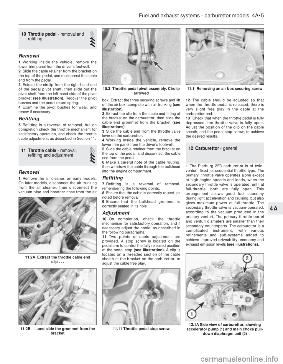
bracket (see illustration). Recover the pivot
bushes and the pedal return spring.
4Examine the pivot bushes for wear, and
renew if necessary.
Refitting
5Refitting is a reversal of removal, but on
completion check the throttle mechanism for
satisfactory operation, and check the throttle
cable adjustment, as described in Section 11.
11Throttle cable - removal,
refitting and adjustment
3
Removal
1Remove the air cleaner, on early models.
On later models, disconnect the air trunking
from the air cleaner, then disconnect the
vacuum pipe and breather hose from the airbox. Extract the three securing screws and lift
off the air box, complete with air trunking(see
illustration).
2Extract the clip from the cable end fitting at
the bracket on the carburettor, then slide the
cable end grommet from the bracket (see
illustrations).
3Slide the cable end from the throttle valve
lever on the carburettor.
4Working inside the vehicle, remove the
lower trim panel from the driver’s footwell.
5Slide the cable retainer from the bracket on
the top of the pedal, and disconnect the cable
end from the pedal.
6Make a careful note of the cable routing,
then withdraw the cable through the bulkhead
into the engine compartment.Refitting
7Refitting is a reversal of removal,
remembering the following points.
8Ensure that the cable is correctly routed, as
noted before removal.
9Ensure that the bulkhead grommet is
correctly seated in its hole.
Adjustment
10On completion, check the throttle
mechanism for satisfactory operation, and if
necessary adjust the cable, as described in
the following paragraphs.
11Two points of cable adjustment are
provided. A stop screw is located on the
pedal arm to control the fully released position
of the pedal stop (see illustration).A clip is
located on a threaded section of the cable
sheath at the bracket on the carburettor, to
adjust the cable free play.12The cable should be adjusted so that
when the throttle pedal is released, there is
very slight free play in the cable at the
carburettor end.
13Check that when the throttle pedal is fully
depressed, the throttle valve is fully open.
Adjust the position of the clip on the cable
sheath, and the pedal stop screw, to achieve
the desired results.
12Carburettor - general
1The Pierburg 2E3 carburettor is of twin-
venturi, fixed-jet sequential throttle type. The
primary throttle valve operates alone except
at high engine speeds and loads, when the
secondary throttle valve is operated, until at
full-throttle, both are fully open. This
arrangement allows good fuel economy
during light acceleration and cruising, but also
gives maximum power at full-throttle. The
secondary throttle valve is vacuum-operated,
according to the vacuum produced in the
primary venturi. The primary throttle barrel
and venturi diameters are smaller than their
secondary counterparts. The carburettor is a
complicated instrument, with various
refinements and sub-systems added to
achieve improved driveability, economy and
exhaust emission levels(see illustrations).
Fuel and exhaust systems - carburettor models 4A•5
11.2A Extract the throttle cable end
clip . . .
12.1A Side view of carburettor, showing
accelerator pump (1) and main choke pull-
down diaphragm unit (2)11.11 Throttle pedal stop screw11.2B . . .and slide the grommet from the
bracket
11.1 Removing an air box securing screw10.3 Throttle pedal pivot assembly. Circlip
arrowed
4A
Page 7 of 525
13Clean any foreign matter from the float
chamber. Renew the float, the float needle
valve and seat if wear is evident, or if the float
is punctured or otherwise damaged. Check
that the needle valve closes completely before
the float reaches the top of its movement. See
Section 15, for details of float level checking.
14Renew the diaphragms in the part-load
enrichment valve and in the accelerator pump.
If additional pump or valve parts are supplied
in the overhaul kit, renew these parts also.
15Further dismantling is not recommended.
Pay particular attention to the throttle opening
mechanism arrangement if it is decided to
dismantle it; the interlocking arrangement is
important.
16Reassemble in the reverse order to
dismantling. Use new gaskets and seals
throughout; lubricate linkages with a smear of
molybdenum based grease.
Refitting
17Carry out the following procedure before
refitting.
a)Position the fast idle adjustment screw on
the highest step of the fast idle cam.
b)Use a gauge rod or twist drill of the
specified diameter to measure the
opening of the primary throttle valve.
c)Adjust if necessary at the fast idle
adjustment screw.
d)Note that this is a preliminary adjustment;
final adjustment of the fast idle speed
should take place with the engine running.
18Refitting is a reversal of removal, but
renew the gasket(s).
19After refitting, carry out the following
checks and adjustments.
20Check the throttle cable free play and
adjust if necessary, as described in Section 11.
21Check and if necessary top-up the
coolant level, as described in Chapter 3.
22Check and if necessary adjust the idle
speed and mixture, as described in Section 14.
14Idle speed and mixture -
adjustment
3
Note: Refer to Section 2 before proceeding.
To carry out the adjustments, an accurate
tachometer and an exhaust gas analyser (CO
meter) will be required
1To check the idle speed and mixture
adjustment, the following conditions must be
met:
a)The engine must be at normal operating
temperature
b)All electrical consumers (cooling fan,
heater blower, headlamps, etc.) must be
switched off
c)The ignition timing and spark plug gaps
must be correctly adjusted - see Chapters
1 and 5
d)The throttle cable free play must be
correctly adjusted - see Section 11
e)The air inlet trunking must be free from
leaks, and the air filter must be cleanf)On automatic models, always select
position, “P”.
2Connect a tachometer and an exhaust gas
analyser to the vehicle, according to the
equipment manufacturer’s instructions.
3Start the engine, and run it at 2000 rpm for
approximately 30 seconds, then allow it to
idle. If the idle speed is outside the specified
limits, adjust by means of the throttle stop
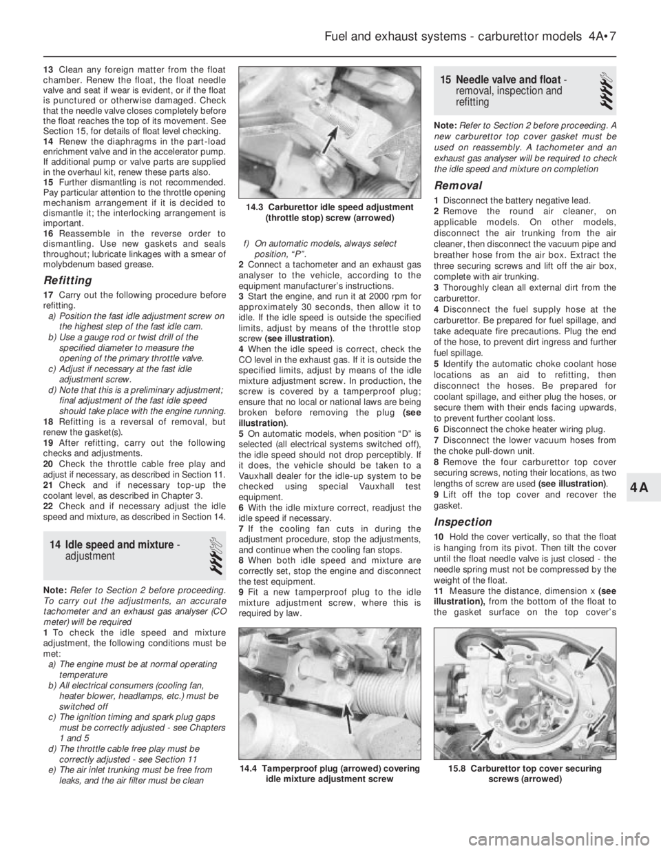
screw (see illustration).
4When the idle speed is correct, check the
CO level in the exhaust gas. If it is outside the
specified limits, adjust by means of the idle
mixture adjustment screw. In production, the
screw is covered by a tamperproof plug;
ensure that no local or national laws are being
broken before removing the plug (see
illustration).
5On automatic models, when position “D” is
selected (all electrical systems switched off),
the idle speed should not drop perceptibly. If
it does, the vehicle should be taken to a
Vauxhall dealer for the idle-up system to be
checked using special Vauxhall test
equipment.
6With the idle mixture correct, readjust the
idle speed if necessary.
7If the cooling fan cuts in during the
adjustment procedure, stop the adjustments,
and continue when the cooling fan stops.
8When both idle speed and mixture are
correctly set, stop the engine and disconnect
the test equipment.
9Fit a new tamperproof plug to the idle
mixture adjustment screw, where this is
required by law.
15Needle valve and float -
removal, inspection and
refitting
4
Note: Refer to Section 2 before proceeding. A
new carburettor top cover gasket must be
used on reassembly. A tachometer and an
exhaust gas analyser will be required to check
the idle speed and mixture on completion
Removal
1Disconnect the battery negative lead.
2Remove the round air cleaner, on
applicable models. On other models,
disconnect the air trunking from the air
cleaner, then disconnect the vacuum pipe and
breather hose from the air box. Extract the
three securing screws and lift off the air box,
complete with air trunking.
3Thoroughly clean all external dirt from the
carburettor.
4Disconnect the fuel supply hose at the
carburettor. Be prepared for fuel spillage, and
take adequate fire precautions. Plug the end
of the hose, to prevent dirt ingress and further
fuel spillage.
5Identify the automatic choke coolant hose
locations as an aid to refitting, then
disconnect the hoses. Be prepared for
coolant spillage, and either plug the hoses, or
secure them with their ends facing upwards,
to prevent further coolant loss.
6Disconnect the choke heater wiring plug.
7Disconnect the lower vacuum hoses from
the choke pull-down unit.
8Remove the four carburettor top cover
securing screws, noting their locations, as two
lengths of screw are used (see illustration).
9Lift off the top cover and recover the
gasket.
Inspection
10Hold the cover vertically, so that the float
is hanging from its pivot. Then tilt the cover
until the float needle valve is just closed - the
needle spring must not be compressed by the
weight of the float.
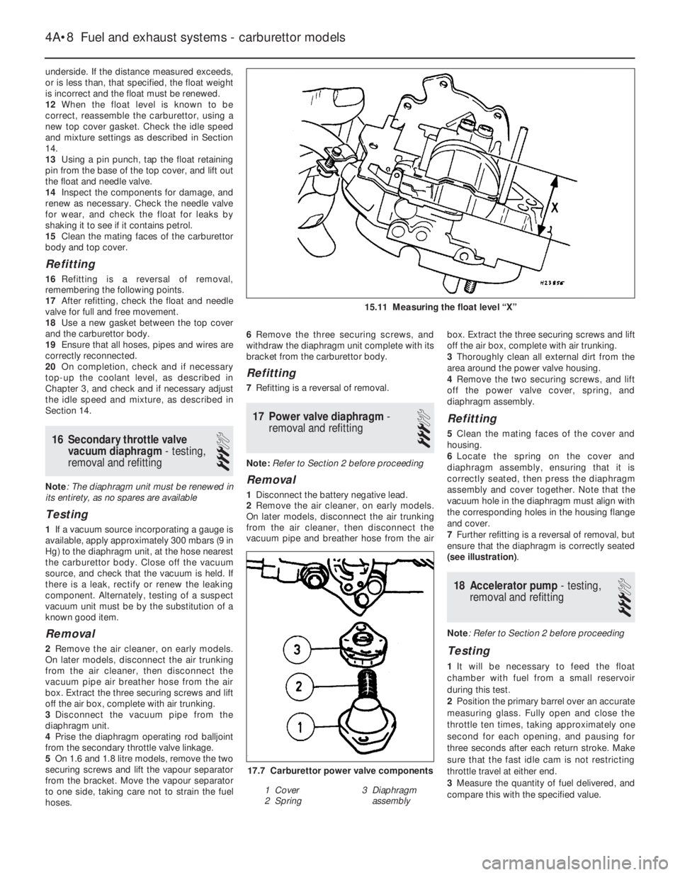
11Measure the distance, dimension x (see
illustration),from the bottom of the float to
the gasket surface on the top cover’s
Fuel and exhaust systems - carburettor models 4A•7
15.8 Carburettor top cover securing
screws (arrowed)14.4 Tamperproof plug (arrowed) covering
idle mixture adjustment screw
14.3 Carburettor idle speed adjustment
(throttle stop) screw (arrowed)
4A
Page 8 of 525
underside. If the distance measured exceeds,
or is less than, that specified, the float weight
is incorrect and the float must be renewed.
12When the float level is known to be
correct, reassemble the carburettor, using a
new top cover gasket. Check the idle speed
and mixture settings as described in Section
14.
13Using a pin punch, tap the float retaining
pin from the base of the top cover, and lift out
the float and needle valve.
14Inspect the components for damage, and
renew as necessary. Check the needle valve
for wear, and check the float for leaks by
shaking it to see if it contains petrol.
15Clean the mating faces of the carburettor
body and top cover.
Refitting
16Refitting is a reversal of removal,
remembering the following points.
17After refitting, check the float and needle
valve for full and free movement.
18Use a new gasket between the top cover
and the carburettor body.
19Ensure that all hoses, pipes and wires are
correctly reconnected.
20On completion, check and if necessary
top-up the coolant level, as described in
Chapter 3, and check and if necessary adjust
the idle speed and mixture, as described in
Section 14.
16Secondary throttle valve
vacuum diaphragm - testing,
removal and refitting
3
Note: The diaphragm unit must be renewed in
its entirety, as no spares are available
Testing
1If a vacuum source incorporating a gauge is
available, apply approximately 300 mbars (9 in
Hg) to the diaphragm unit, at the hose nearest
the carburettor body. Close off the vacuum
source, and check that the vacuum is held. If
there is a leak, rectify or renew the leaking
component. Alternately, testing of a suspect
vacuum unit must be by the substitution of a
known good item.
Removal
2Remove the air cleaner, on early models.
On later models, disconnect the air trunking
from the air cleaner, then disconnect the
vacuum pipe air breather hose from the air
box. Extract the three securing screws and lift
off the air box, complete with air trunking.
3Disconnect the vacuum pipe from the
diaphragm unit.
4Prise the diaphragm operating rod balljoint
from the secondary throttle valve linkage.
5On 1.6 and 1.8 litre models, remove the two
securing screws and lift the vapour separator
from the bracket. Move the vapour separator
to one side, taking care not to strain the fuel
hoses.6Remove the three securing screws, and
withdraw the diaphragm unit complete with its
bracket from the carburettor body.
Refitting
7Refitting is a reversal of removal.
17Power valve diaphragm -
removal and refitting
3
Note: Refer to Section 2 before proceeding
Removal
1Disconnect the battery negative lead.
2Remove the air cleaner, on early models.
On later models, disconnect the air trunking
from the air cleaner, then disconnect the
vacuum pipe and breather hose from the airbox. Extract the three securing screws and lift
off the air box, complete with air trunking.
3Thoroughly clean all external dirt from the
area around the power valve housing.
4Remove the two securing screws, and lift
off the power valve cover, spring, and
diaphragm assembly.
Refitting
5Clean the mating faces of the cover and
housing.
6Locate the spring on the cover and
diaphragm assembly, ensuring that it is
correctly seated, then press the diaphragm
assembly and cover together. Note that the
vacuum hole in the diaphragm must align with
the corresponding holes in the housing flange
and cover.
7Further refitting is a reversal of removal, but
ensure that the diaphragm is correctly seated
(see illustration).
18Accelerator pump - testing,
removal and refitting
3
Note: Refer to Section 2 before proceeding
Testing
1It will be necessary to feed the float
chamber with fuel from a small reservoir
during this test.
2Position the primary barrel over an accurate
measuring glass. Fully open and close the
throttle ten times, taking approximately one
second for each opening, and pausing for
three seconds after each return stroke. Make
sure that the fast idle cam is not restricting
throttle travel at either end.
3Measure the quantity of fuel delivered, and
compare this with the specified value.
4A•8Fuel and exhaust systems - carburettor models
15.11 Measuring the float level “X”
17.7 Carburettor power valve components
1 Cover
2 Spring3 Diaphragm
assembly
Page 9 of 525
4If adjustment is necessary, release the
clamp screw and turn the cam plate in the
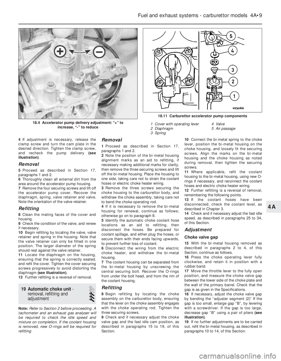
desired direction. Tighten the clamp screw,
and recheck the pump delivery (see
illustration).
Removal
5Proceed as described in Section 17,
paragraphs 1 and 2.
6Thoroughly clean all external dirt from the
area around the accelerator pump housing.
7Remove the four securing screws and lift off
the accelerator pump cover. Recover the
diaphragm, spring, valve retainer and valve.
Note the orientation of the valve retainer.
Refitting
8Clean the mating faces of the cover and
housing.
9Check the condition of the valve, and renew
if necessary.
10Begin refitting by locating the valve, valve
retainer and spring in the housing. Note that
the valve retainer can only be fitted in one
position. The larger diameter of the spring
should rest against the valve retainer.
11Locate the diaphragm on the housing,
ensuring that the spring is correctly seated,
and refit the cover. Tighten the cover securing
screws progressively to avoid distorting the
diaphragm (see illustration).
12Further refitting is a reversal of removal.
19Automatic choke unit -
removal, refitting and
adjustment
3
Note: Refer to Section 2 before proceeding. A
tachometer and an exhaust gas analyser will
be required to check the idle speed and
mixture on completion. If the coolant housing
is removed, new O-rings will be required for
refitting
Removal
1Proceed as described in Section 17,
paragraphs 1 and 2.
2Note the position of the bi-metal housing
alignment marks as an aid to refitting, if
necessary making additional marks for clarity,
then remove the three securing screws and lift
off the bi-metal housing. Place the housing to
one side, taking care not to strain the coolant
hoses or electric choke heater wiring.
3Remove the three screws securing the
choke housing to the carburettor body, and
withdraw the choke assembly, taking care not
to bend the choke operating rod.
4If it is necessary to remove the bi-metal
housing for renewal, continue as follows;
otherwise go on to paragraph 8.
5Identify the automatic choke coolant hose
locations as an aid to refitting, then
disconnect the hoses. Be prepared for
coolant spillage, and either plug the hoses, or
secure them with their ends facing upwards,
to prevent further loss of coolant.
6Disconnect the wiring from the electric
choke heater, and withdraw the bi-metal
housing.
7The coolant housing can be separated from
the bi-metal housing by unscrewing the
central securing bolt. Recover the O-rings
from under the bolt head, and from the rim of
the coolant housing.
Refitting
8Begin refitting by locating the choke
assembly on the carburettor body, ensuring
that the lever on the choke assembly engages
with the choke operating rod. Tighten the
three securing screws.
9Check and if necessary adjust the choke
valve gap and the fast idle cam position, as
described in paragraphs 15 to 19, of this
Section.10Connect the bi-metal spring to the choke
lever, position the bi-metal housing on the
choke housing, and loosely fit the securing
screws. Align the marks on the bi-metal
housing and the choke housing as noted
during removal, then tighten the securing
screws.
11Where applicable, refit the coolant
housing to the bi-metal housing, using new O-
rings if necessary, and reconnect the coolant
hoses and electric choke heater wiring.
12Further refitting is a reversal of removal,
remembering the following points.
13If the coolant hoses have been
disconnected, check the coolant level, as
described in Chapter 3.
14Check and if necessary adjust the fast idle
speed, as described in paragraphs 25 to 34,
of this Section.
Adjustment
Choke valve gap
15With the bi-metal housing removed as
described in paragraphs 2 to 4, of this
Section, continue as follows.
16Press the choke operating lever fully
clockwise, and retain it in position with a
rubber band.
17Move the throttle lever to the fully open
position, and measure the choke valve gap
between the lower side of the choke plate and
the wall of the primary barrel. Check that the
gap is as given in the Specifications.
18If necessary, adjust the choke valve gap
by bending the “adjuster segment (2)” If the
gap is too small, enlarge gap “B”, by levering
with a screwdriver. If the gap is too large,
decrease gap “B” using a pair of pliers (see
illustration).
19If no further adjustments are to be carried
out, refit the bi-metal housing, as described in
paragraphs 10 to 14, of this Section.
Fuel and exhaust systems - carburettor models 4A•9
18.11 Carburettor accelerator pump components
1 Cover with operating lever
2 Diaphragm
3 Spring4 Valve
5 Air passage
18.4 Accelerator pump delivery adjustment: “+” to
increase, “-” to reduce
4A
Page 12 of 525
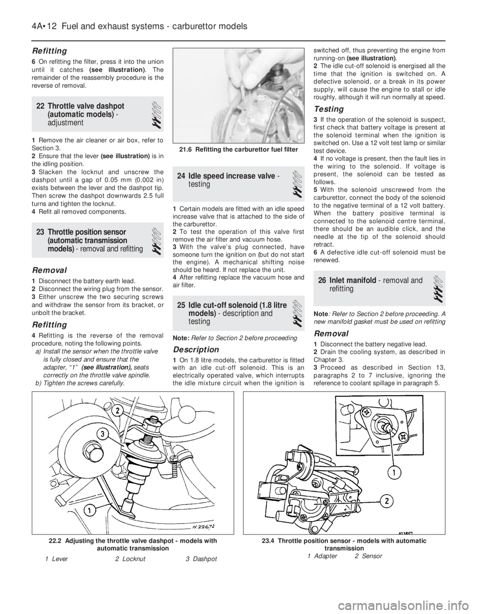
Refitting
6On refitting the filter, press it into the union
until it catches (see illustration). The
remainder of the reassembly procedure is the
reverse of removal.
22Throttle valve dashpot
(automatic models) -
adjustment
2
1Remove the air cleaner or air box, refer to
Section 3.
2Ensure that the lever (see illustration)is in
the idling position.
3Slacken the locknut and unscrew the
dashpot until a gap of 0.05 mm (0.002 in)
exists between the lever and the dashpot tip.
Then screw the dashpot downwards 2.5 full
turns and tighten the locknut.
4Refit all removed components.
23Throttle position sensor
(automatic transmission
models) - removal and refitting
2
Removal
1Disconnect the battery earth lead.
2Disconnect the wiring plug from the sensor.
3Either unscrew the two securing screws
and withdraw the sensor from its bracket, or
unbolt the bracket.
Refitting
4Refitting is the reverse of the removal
procedure, noting the following points.
a)Install the sensor when the throttle valve
is fully closed and ensure that the
adapter, “1” (see illustration),seats
correctly on the throttle valve spindle.
b)Tighten the screws carefully.
24Idle speed increase valve -
testing
2
1Certain models are fitted with an idle speed
increase valve that is attached to the side of
the carburettor.
2To test the operation of this valve first
remove the air filter and vacuum hose.
3With the valve’s plug connected, have
someone turn the ignition on (but do not start
the engine). A mechanical shifting noise
should be heard. If not replace the unit.
4After refitting replace the vacuum hose and
air filter.
25Idle cut-off solenoid (1.8 litre
models) - description and
testing
2
Note: Refer to Section 2 before proceeding
Description
1On 1.8 litre models, the carburettor is fitted
with an idle cut-off solenoid. This is an
electrically operated valve, which interrupts
the idle mixture circuit when the ignition isswitched off, thus preventing the engine from
running-on (see illustration).
2The idle cut-off solenoid is energised all the
time that the ignition is switched on. A
defective solenoid, or a break in its power
supply, will cause the engine to stall or idle
roughly, although it will run normally at speed.
Testing
3If the operation of the solenoid is suspect,
first check that battery voltage is present at
the solenoid terminal when the ignition is
switched on. Use a 12 volt test lamp or similar
test device.
4If no voltage is present, then the fault lies in
the wiring to the solenoid. If voltage is
present, the solenoid can be tested as
follows.
5With the solenoid unscrewed from the
carburettor, connect the body of the solenoid
to the negative terminal of a 12 volt battery.
When the battery positive terminal is
connected to the solenoid centre terminal,
there should be an audible click, and the
needle at the tip of the solenoid should
retract.
6A defective idle cut-off solenoid must be
renewed.
26Inlet manifold - removal and
refitting
3
Note: Refer to Section 2 before proceeding. A
new manifold gasket must be used on refitting
Removal
1Disconnect the battery negative lead.
2Drain the cooling system, as described in
Chapter 3.
3Proceed as described in Section 13,
paragraphs 2 to 7 inclusive, ignoring the
reference to coolant spillage in paragraph 5.
4A•12Fuel and exhaust systems - carburettor models
21.6 Refitting the carburettor fuel filter
23.4 Throttle position sensor - models with automatic
transmission
1 Adapter 2 Sensor22.2 Adjusting the throttle valve dashpot - models with
automatic transmission
1 Lever2 Locknut3 Dashpot
Page 15 of 525
12
Wiper blades
Type . . . . . . . . . . . . . . . . . . . . . . . . . . . . . . . . . . . . . . . . . . . . . . . . . . . . 19 ins. Champion X-4803
Fuses
Rating:
Red . . . . . . . . . . . . . . . . . . . . . . . . . . . . . . . . . . . . . . . . . . . . . . . . . . . 10 A
Blue . . . . . . . . . . . . . . . . . . . . . . . . . . . . . . . . . . . . . . . . . . . . . . . . . . . 15 A
Yellow . . . . . . . . . . . . . . . . . . . . . . . . . . . . . . . . . . . . . . . . . . . . . . . . . 20 A
Green . . . . . . . . . . . . . . . . . . . . . . . . . . . . . . . . . . . . . . . . . . . . . . . . . 30 A
Torque wrench settingsNm lbf ft
Airbag unit to steering wheel . . . . . . . . . . . . . . . . . . . . . . . . . . . . . . . . . 10 7
Airbag control . . . . . . . . . . . . . . . . . . . . . . . . . . . . . . . . . . . . . . . . . . . . . 10 7
Brackets, passenger airbag . . . . . . . . . . . . . . . . . . . . . . . . . . . . . . . . . . 22 16
Passenger airbag to bracket . . . . . . . . . . . . . . . . . . . . . . . . . . . . . . . . . 8 6
Steering to column . . . . . . . . . . . . . . . . . . . . . . . . . . . . . . . . . . . . . . . . . 25 18
Chapter 12
Body electrical systems
Aerial - removal and refitting . . . . . . . . . . . . . . . . . . . . . . . . . . . . . . .47
Aerial mast, electric - removal and refitting . . . . . . . . . . . . . . . . . . . .48
Airbag - general . . . . . . . . . . . . . . . . . . . . . . . . . . . . . . . . . . . . . . . . .55
Airbag contact unit - removal and refitting . . . . . . . . . . . . . . . . . . . . .58
Airbag control unit - removal and refitting . . . . . . . . . . . . . . . . . . . . .61
Airbag unit, drivers side - removal and refitting . . . . . . . . . . . . . . . . .56
Airbag unit, passengers side - removal and refitting . . . . . . . . . . . . .59
Anti-theft alarm - general . . . . . . . . . . . . . . . . . . . . . . . . . . . . . . . . . .53
Anti-theft alarm system components - removal and refitting . . . . . . .54
Bracket, passenger airbag unit - removal and refitting . . . . . . . . . . .60
Brake lamp switch - removal and refitting . . . . . . . . . . . . . . . . . . . . .12
Central door locking components - removal and refitting . . . . . . . . .46
Check control system components - removal and refitting . . . . . . . .21
Cigarette lighter - removal and refitting . . . . . . . . . . . . . . . . . . . . . . .15
Clock - removal and refitting . . . . . . . . . . . . . . . . . . . . . . . . . . . . . . .16
Courtesy lamp switch - removal and refitting . . . . . . . . . . . . . . . . . . .10
Direction indicator/lighting switch - removal and refitting . . . . . . . . . .5
Electric door mirror switch - removal and refitting . . . . . . . . . . . . . . . .8
Electric window components - removal and refitting . . . . . . . . . . . . .44
Electric window controls - programming . . . . . . . . . . . . . . . . . . . . . .45
Electrical fault-finding - general information . . . . . . . . . . . . . . . . . . . . .2
Exterior lamp bulbs - renewal . . . . . . . . . . . . . . . . . . . . . . . . . . . . . . .34
Facia panel switches - removal and refitting . . . . . . . . . . . . . . . . . . . .7
Front indicator lamp unit - removal and refitting . . . . . . . . . . . . . . . .29
Front foglamp - removal, refitting and adjustment . . . . . . . . . . . . . . .31
Fuses and relays - general . . . . . . . . . . . . . . . . . . . . . . . . . . . . . . . . . .3
General information and precautions . . . . . . . . . . . . . . . . . . . . . . . . . .1
Handbrake “on” warning lamp switch - removal and refitting . . . . . .13
Headlamp aim adjustment motor - removal and refitting . . . . . . . . . .26
Headlamp dim-dip system - general, removal and refitting . . . . . . . .28
Headlamp unit - removal and refitting . . . . . . . . . . . . . . . . . . . . . . . .25
Headlamp washer fluid non-return valve - removal and refitting . . . .43Headlamp wiper motor - removal and refitting . . . . . . . . . . . . . . . . . .40
Headlamps - alignment . . . . . . . . . . . . . . . . . . . . . . . . . . . . . . . . . . .27
Heated front seats - general . . . . . . . . . . . . . . . . . . . . . . . . . . . . . . . .17
Horn(s) - removal and refitting . . . . . . . . . . . . . . . . . . . . . . . . . . . . . .22
Ignition switch and lock cylinder - removal and refitting . . . . . . . . . . .4
Instrument panel - removal and refitting . . . . . . . . . . . . . . . . . . . . . .18
Instrument panel components - removal and refitting . . . . . . . . . . . .19
Interior lamp bulbs - renewal . . . . . . . . . . . . . . . . . . . . . . . . . . . . . . .24
Interior lamps - removal and refitting . . . . . . . . . . . . . . . . . . . . . . . . .23
Luggage compartment lamp switch - removal and refitting . . . . . . .11
Number plate lamp - removal and refitting . . . . . . . . . . . . . . . . . . . . .33
Oil pressure warning lamp switch - removal and refitting . . . . . . . . .14
Radio/cassette player - removal and refitting . . . . . . . . . . . . . . . . . . .50
Rear lamp unit - removal and refitting . . . . . . . . . . . . . . . . . . . . . . . .32
Reversing lamp switch . . . . . . . . . . . . . . . . . . . . . . . . .See Chapter 7A
Side repeater lamp - removal and refitting . . . . . . . . . . . . . . . . . . . . .30
Speakers - removal and refitting . . . . . . . . . . . . . . . . . . . . . . . . . . . .49
Speedometer cable - removal and refitting . . . . . . . . . . . . . . . . . . . .52
Steering wheel (with airbag) - removal and refitting . . . . . . . . . . . . . .57
Sunroof motor - removal and refitting . . . . . . . . . . . . . . . . . . . . . . . .51
Sunroof operating switch - removal and refitting . . . . . . . . . . . . . . . . .9
Tailgate wiper motor - removal and refitting . . . . . . . . . . . . . . . . . . . .39
Trip computer components - removal and refitting . . . . . . . . . . . . . .20
Wash/wipe switch - removal and refitting . . . . . . . . . . . . . . . . . . . . . .6
Washer fluid reservoir - removal and refitting . . . . . . . . . . . . . . . . . . .41
Washer nozzles - removal and refitting . . . . . . . . . . . . . . . . . . . . . . .37
Washer pump - removal and refitting . . . . . . . . . . . . . . . . . . . . . . . . .42
Windscreen wiper motor and linkage - removal and refitting . . . . . . .38
Wiper arms - removal and refitting . . . . . . . . . . . . . . . . . . . . . . . . . . .36
Wiper blades - renewal . . . . . . . . . . . . . . . . . . . . . . . . . . . . . . . . . . . .35
Wiring diagrams - general . . . . . . . . . . . . . . . . . . . . . . . . . . . . . . . . .62
12•1
Specifications Contents
Easy,suitable for
novice with little
experienceFairly easy,suitable
for beginner with
some experienceFairly difficult,
suitable for competent
DIY mechanic
Difficult,suitable for
experienced DIY
mechanicVery difficult,
suitable for expert DIY
or professional
Degrees of difficulty
54321
Page 20 of 525
3To remove the cigarette lighter assembly,
simply pull it from the illumination ring
assembly. If desired, the illumination ring
assembly can be removed, by pulling it from
the housing after depressing the retaining
clips.
Refitting
4Refitting is a reversal of removal.
16Clock - removal and refitting
2
Removal
1Disconnect the battery negative lead.
2Using a thin-bladed screwdriver, carefully
prise the clock from the facia panel.
3Disconnect the wiring plugs and withdraw
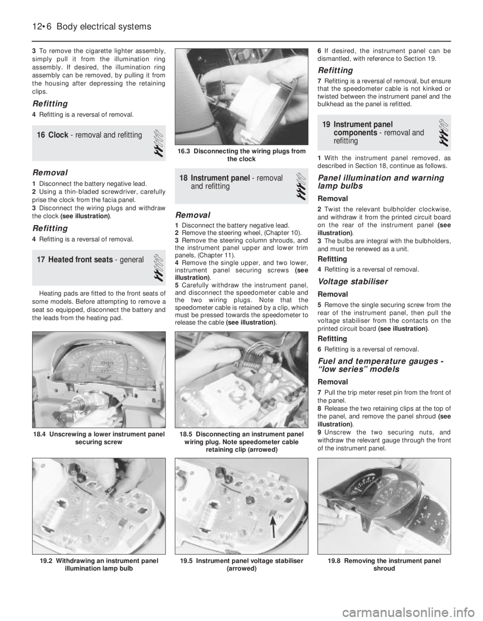
the clock (see illustration).
Refitting
4Refitting is a reversal of removal.
17Heated front seats - general
2
Heating pads are fitted to the front seats of
some models. Before attempting to remove a
seat so equipped, disconnect the battery and
the leads from the heating pad.
18Instrument panel -removal
and refitting
3
Removal
1Disconnect the battery negative lead.
2Remove the steering wheel, (Chapter 10).
3Remove the steering column shrouds, and
the instrument panel upper and lower trim
panels, (Chapter 11).
4Remove the single upper, and two lower,
instrument panel securing screws (see
illustration).
5Carefully withdraw the instrument panel,
and disconnect the speedometer cable and
the two wiring plugs. Note that the
speedometer cable is retained by a clip, which
must be pressed towards the speedometer to
release the cable (see illustration).6If desired, the instrument panel can be
dismantled, with reference to Section 19.
Refitting
7Refitting is a reversal of removal, but ensure
that the speedometer cable is not kinked or
twisted between the instrument panel and the
bulkhead as the panel is refitted.
19Instrument panel
components - removal and
refitting
3
1With the instrument panel removed, as
described in Section 18, continue as follows.
Panel illumination and warning
lamp bulbs
Removal
2Twist the relevant bulbholder clockwise,
and withdraw it from the printed circuit board
on the rear of the instrument panel (see
illustration).
3The bulbs are integral with the bulbholders,
and must be renewed as a unit.
Refitting
4Refitting is a reversal of removal.
Voltage stabiliser
Removal
5Remove the single securing screw from the
rear of the instrument panel, then pull the
voltage stabiliser from the contacts on the
printed circuit board (see illustration).
Refitting
6Refitting is a reversal of removal.
Fuel and temperature gauges -
“low series” models
Removal
7Pull the trip meter reset pin from the front of
the panel.
8Release the two retaining clips at the top of
the panel, and remove the panel shroud (see
illustration).
9Unscrew the two securing nuts, and
withdraw the relevant gauge through the front
of the instrument panel.
12•6Body electrical systems
16.3 Disconnecting the wiring plugs from
the clock
18.5 Disconnecting an instrument panel
wiring plug. Note speedometer cable
retaining clip (arrowed)
19.8 Removing the instrument panel
shroud19.5 Instrument panel voltage stabiliser
(arrowed)19.2 Withdrawing an instrument panel
illumination lamp bulb
18.4 Unscrewing a lower instrument panel
securing screw
Page 21 of 525
Refitting
10Refitting is a reversal of removal.
Fuel and temperature gauge
assembly -“high series” models
11The procedure is as described in
paragraphs 7 to 10 inclusive, except that the
gauge assembly is secured by four nuts.
Tachometer
12The procedure is as described in
paragraphs 7 to 10 inclusive except that the
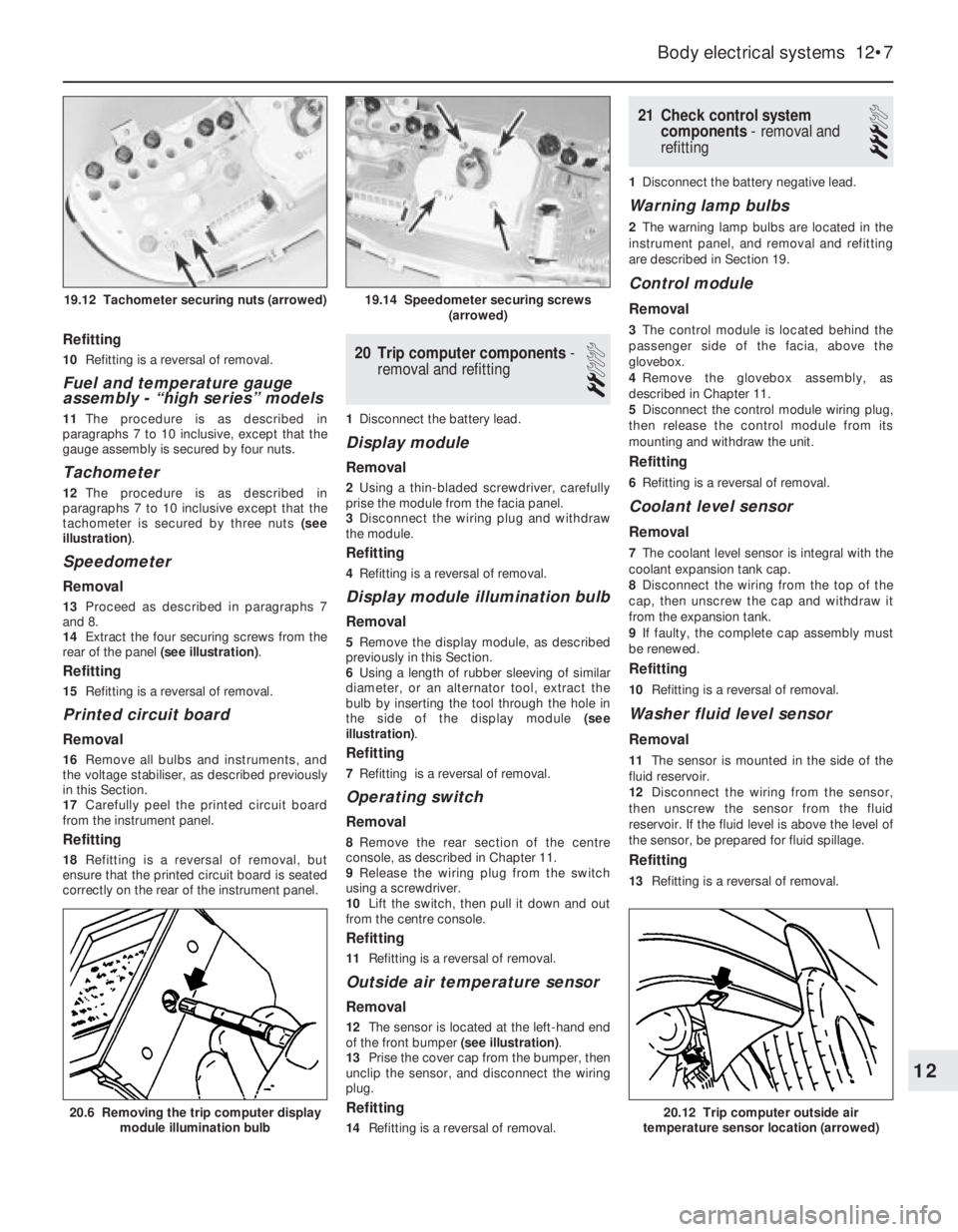
tachometer is secured by three nuts (see
illustration).
Speedometer
Removal
13Proceed as described in paragraphs 7
and 8.
14Extract the four securing screws from the
rear of the panel (see illustration).
Refitting
15Refitting is a reversal of removal.
Printed circuit board
Removal
16Remove all bulbs and instruments, and
the voltage stabiliser, as described previously
in this Section.
17Carefully peel the printed circuit board
from the instrument panel.
Refitting
18Refitting is a reversal of removal, but
ensure that the printed circuit board is seated
correctly on the rear of the instrument panel.
20Trip computer components -
removal and refitting
2
1Disconnect the battery lead.
Display module
Removal
2Using a thin-bladed screwdriver, carefully
prise the module from the facia panel.
3Disconnect the wiring plug and withdraw
the module.
Refitting
4Refitting is a reversal of removal.
Display module illumination bulb
Removal
5Remove the display module, as described
previously in this Section.
6Using a length of rubber sleeving of similar
diameter, or an alternator tool, extract the
bulb by inserting the tool through the hole in
the side of the display module (see
illustration).
Refitting
7Refitting is a reversal of removal.
Operating switch
Removal
8Remove the rear section of the centre
console, as described in Chapter 11.
9Release the wiring plug from the switch
using a screwdriver.
10Lift the switch, then pull it down and out
from the centre console.
Refitting
11Refitting is a reversal of removal.
Outside air temperature sensor
Removal
12The sensor is located at the left-hand end
of the front bumper (see illustration).
13Prise the cover cap from the bumper, then
unclip the sensor, and disconnect the wiring
plug.
Refitting
14Refitting is a reversal of removal.
21Check control system
components - removal and
refitting
3
1Disconnect the battery negative lead.
Warning lamp bulbs
2The warning lamp bulbs are located in the
instrument panel, and removal and refitting
are described in Section 19.
Control module
Removal
3The control module is located behind the
passenger side of the facia, above the
glovebox.
4Remove the glovebox assembly, as
described in Chapter 11.
5Disconnect the control module wiring plug,
then release the control module from its
mounting and withdraw the unit.
Refitting
6Refitting is a reversal of removal.
Coolant level sensor
Removal
7The coolant level sensor is integral with the
coolant expansion tank cap.
8Disconnect the wiring from the top of the
cap, then unscrew the cap and withdraw it
from the expansion tank.
9If faulty, the complete cap assembly must
be renewed.
Refitting
10Refitting is a reversal of removal.
Washer fluid level sensor
Removal
11The sensor is mounted in the side of the
fluid reservoir.
12Disconnect the wiring from the sensor,
then unscrew the sensor from the fluid
reservoir. If the fluid level is above the level of
the sensor, be prepared for fluid spillage.
Refitting
13Refitting is a reversal of removal.
Body electrical systems 12•7
20.6 Removing the trip computer display
module illumination bulb20.12 Trip computer outside air
temperature sensor location (arrowed)
19.14 Speedometer securing screws
(arrowed)19.12 Tachometer securing nuts (arrowed)
12
Page 22 of 525
Brake fluid level sensor
14The procedure is as described for the
coolant level sensor in paragraphs 7 to 10
inclusive.
Engine oil level sensor
Removal
15Apply the handbrake, jack up the front of
the vehicle, and support securely on axle
stands (see “Jacking and Vehicle Support”)
positioned under the body side members.
16On DOHC models, remove the engine
undershield, as described in Chapter 11.
17Disconnect the sensor wiring plug.
18Unscrew the three or four sensor securing
screws, as applicable, and withdraw the
sensor, manipulating the float through the hole
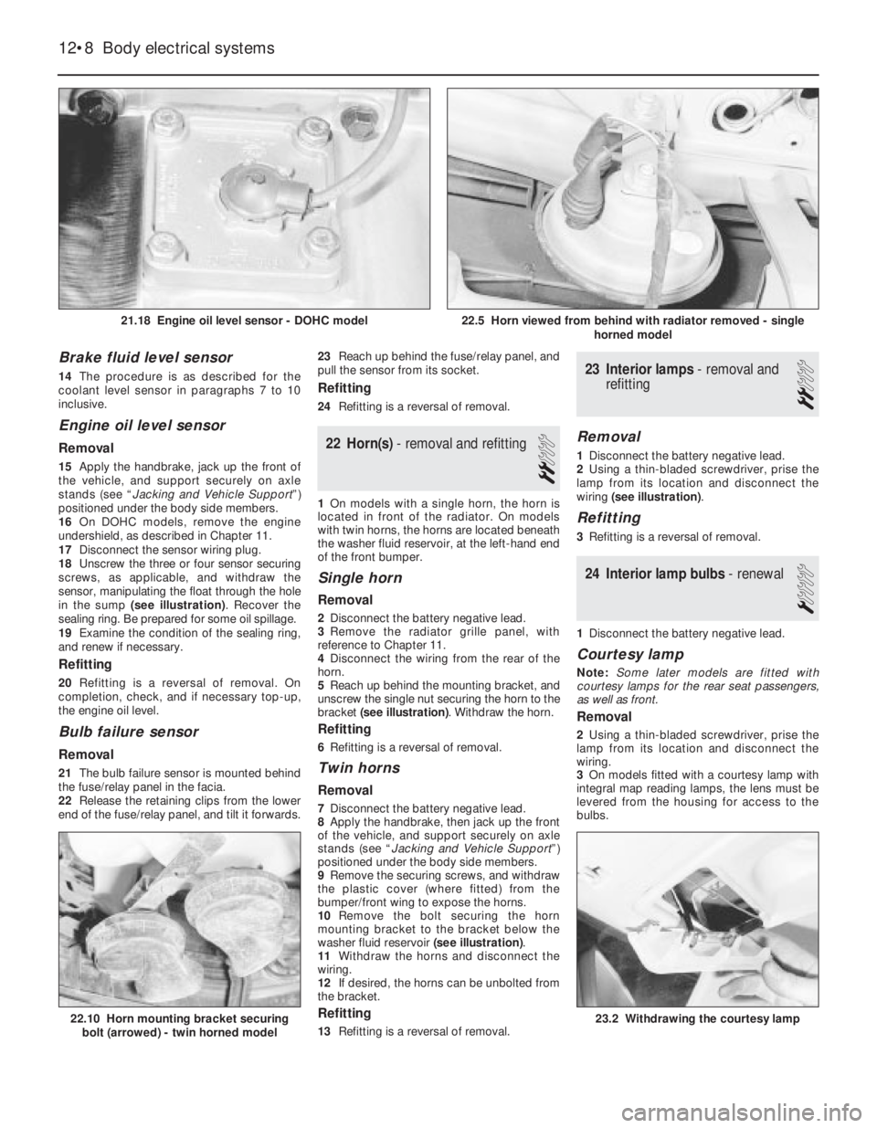
in the sump (see illustration). Recover the
sealing ring. Be prepared for some oil spillage.
19Examine the condition of the sealing ring,
and renew if necessary.
Refitting
20Refitting is a reversal of removal. On
completion, check, and if necessary top-up,
the engine oil level.
Bulb failure sensor
Removal
21The bulb failure sensor is mounted behind
the fuse/relay panel in the facia.
22Release the retaining clips from the lower
end of the fuse/relay panel, and tilt it forwards.23Reach up behind the fuse/relay panel, and
pull the sensor from its socket.
Refitting
24Refitting is a reversal of removal.
22Horn(s) - removal and refitting
2
1On models with a single horn, the horn is
located in front of the radiator. On models
with twin horns, the horns are located beneath
the washer fluid reservoir, at the left-hand end
of the front bumper.
Single horn
Removal
2Disconnect the battery negative lead.
3Remove the radiator grille panel, with
reference to Chapter 11.
4Disconnect the wiring from the rear of the
horn.
5Reach up behind the mounting bracket, and
unscrew the single nut securing the horn to the
bracket (see illustration). Withdraw the horn.
Refitting
6Refitting is a reversal of removal.
Twin horns
Removal
7Disconnect the battery negative lead.
8Apply the handbrake, then jack up the front
of the vehicle, and support securely on axle
stands (see “Jacking and Vehicle Support”)
positioned under the body side members.
9Remove the securing screws, and withdraw
the plastic cover (where fitted) from the
bumper/front wing to expose the horns.
10Remove the bolt securing the horn
mounting bracket to the bracket below the
washer fluid reservoir (see illustration).
11Withdraw the horns and disconnect the
wiring.
12If desired, the horns can be unbolted from
the bracket.
Refitting
13Refitting is a reversal of removal.
23Interior lamps - removal and
refitting
2
Removal
1Disconnect the battery negative lead.
2Using a thin-bladed screwdriver, prise the
lamp from its location and disconnect the
wiring (see illustration).
Refitting
3Refitting is a reversal of removal.
24Interior lamp bulbs - renewal
1
1Disconnect the battery negative lead.
Courtesy lamp
Note: Some later models are fitted with
courtesy lamps for the rear seat passengers,
as well as front.
Removal
2Using a thin-bladed screwdriver, prise the
lamp from its location and disconnect the
wiring.
3On models fitted with a courtesy lamp with
integral map reading lamps, the lens must be
levered from the housing for access to the
bulbs.
12•8Body electrical systems
21.18 Engine oil level sensor - DOHC model
22.10 Horn mounting bracket securing
bolt (arrowed) - twin horned model23.2 Withdrawing the courtesy lamp
22.5 Horn viewed from behind with radiator removed - single
horned model
Page 24 of 525
27Headlamps -alignment
2
1Correct alignment of the headlamp beams
is most important, not only to ensure good
vision for the driver, but also to protect other
drivers from being dazzled.
2Accurate alignment should be carried out
using optical beam setting equipment.
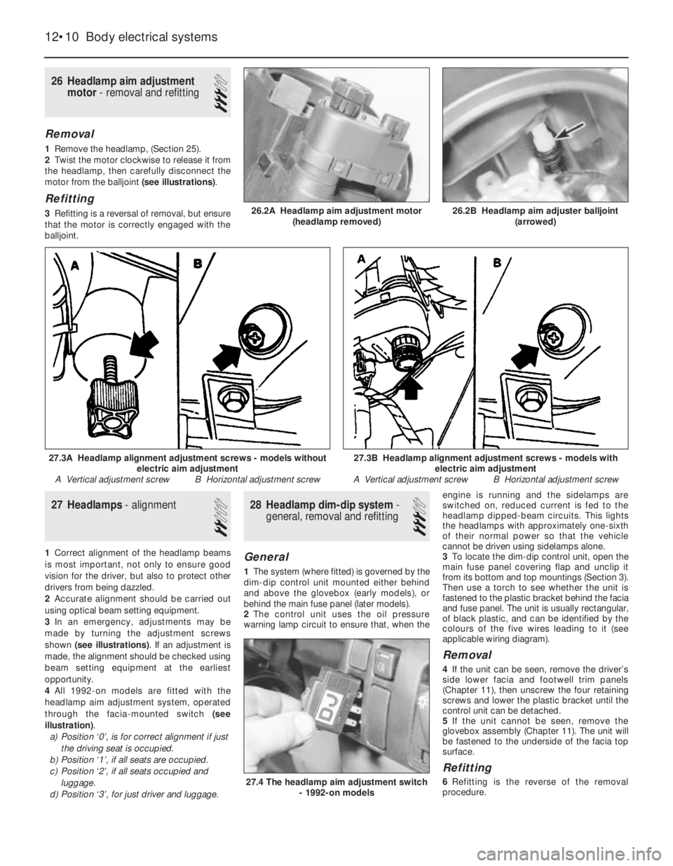
3In an emergency, adjustments may be
made by turning the adjustment screws
shown (see illustrations). If an adjustment is
made, the alignment should be checked using
beam setting equipment at the earliest
opportunity.
4All 1992-on models are fitted with the
headlamp aim adjustment system, operated
through the facia-mounted switch (see
illustration).
a)Position ‘0’, is for correct alignment if just
the driving seat is occupied.
b)Position ‘1’, if all seats are occupied.
c)Position ‘2’, if all seats occupied and
luggage.
d)Position ‘3’, for just driver and luggage.
28Headlamp dim-dip system -
general, removal and refitting
3
General
1The system (where fitted) is governed by the
dim-dip control unit mounted either behind
and above the glovebox (early models), or
behind the main fuse panel (later models).
2The control unit uses the oil pressure
warning lamp circuit to ensure that, when theengine is running and the sidelamps are
switched on, reduced current is fed to the
headlamp dipped-beam circuits. This lights
the headlamps with approximately one-sixth
of their normal power so that the vehicle
cannot be driven using sidelamps alone.
3To locate the dim-dip control unit, open the
main fuse panel covering flap and unclip it
from its bottom and top mountings (Section 3).
Then use a torch to see whether the unit is
fastened to the plastic bracket behind the facia
and fuse panel. The unit is usually rectangular,
of black plastic, and can be identified by the
colours of the five wires leading to it (see
applicable wiring diagram).
Removal
4If the unit can be seen, remove the driver’s
side lower facia and footwell trim panels
(Chapter 11), then unscrew the four retaining
screws and lower the plastic bracket until the
control unit can be detached.
5If the unit cannot be seen, remove the
glovebox assembly (Chapter 11). The unit will
be fastened to the underside of the facia top
surface.
Refitting
6Refitting is the reverse of the removal
procedure.
26Headlamp aim adjustment
motor - removal and refitting
3
Removal
1Remove the headlamp, (Section 25).
2Twist the motor clockwise to release it from
the headlamp, then carefully disconnect the
motor from the balljoint (see illustrations).
Refitting
3Refitting is a reversal of removal, but ensure
that the motor is correctly engaged with the
balljoint.
12•10Body electrical systems
26.2A Headlamp aim adjustment motor
(headlamp removed)
27.4 The headlamp aim adjustment switch
- 1992-on models
27.3B Headlamp alignment adjustment screws - models with
electric aim adjustment
A Vertical adjustment screw B Horizontal adjustment screw27.3A Headlamp alignment adjustment screws - models without
electric aim adjustment
A Vertical adjustment screw B Horizontal adjustment screw
26.2B Headlamp aim adjuster balljoint
(arrowed)