engine overheat OPEL CALIBRA 1988 Service Repair Manual
[x] Cancel search | Manufacturer: OPEL, Model Year: 1988, Model line: CALIBRA, Model: OPEL CALIBRA 1988Pages: 525, PDF Size: 58.26 MB
Page 129 of 525
b)Always keep the ignition and fuel systems
well maintained according to the
manufacturers schedule (see “Routine
maintenance” and the relevant Chapter).
In particular, ensure that the air cleaner
filter element, the fuel filter and the spark
plugs are renewed at the correct intervals.
If the inlet air/fuel mixture is allowed to
become too rich due to neglect, the
unburned surplus will enter and burn in
the catalytic converter, overheating the
element and eventually destroying the
converter.
c)If the engine develops a misfire, do not
drive the vehicle at all (or at least as little
as possible) until the fault is cured. The
misfire will allow unburned fuel to enter
the converter, which will result in its
overheating, as noted above.
d)The engine control indicator (the outline
of an engine with a lightning symbol
superimposed), will light when the ignition
is switched on and the engine is started,
then it will go out. While it may light briefly
while the engine is running, it should go
out again immediately and stays unlit. If it
lights and stays on while the engine is
running, seek the advice of a Vauxhall
dealer as soon as possible. A fault has
occurred in the fuel injection/ignition
system that, apart from increasing fuel
consumption and impairing the engine’s
performance, may damage the catalytic
converter.
e)DO NOT push or tow-start the vehicle.
This will soak the catalytic converter in
unburned fuel causing it to overheat when
the engine does start see (b) above.
f)DO NOT switch off the ignition at high
engine speeds. If the ignition is switched
off at anything above idle speed,
unburned fuel will enter the (very hot)
catalytic converter, with the possible risk
of its igniting on the element and
damaging the converter.
g)DO NOT use fuel or engine oil additives.
These may contain substances harmful to
the catalytic converter.
h)DO NOT continue to use the vehicle if the
engine burns oil to the extent of leaving a
visible trail of blue smoke. The unburned
carbon deposits will clog the converter
passages and reduce its efficiency; in
severe cases the element will overheat.
i)Remember that the catalytic converter
operates at very high temperatures hence
the heat shields on the vehicle’s under-
body and the casing will become hot
enough to ignite combustible materials
that brush against it. DO NOT, therefore,
park the vehicle in dry undergrowth, over
long grass or over piles of dead leaves.
j)Remember that the catalytic converter is
FRAGlLE. Do not strike it with tools during
servicing work. Take great care when
working on the exhaust system. Ensure
that the converter is well clear of any
jacks or other lifting gear used to raise thevehicle. Do not drive the vehicle over
rough ground, road humps, etc., in such a
way as to ground the exhaust system.
k)In some cases, particularly when the
vehicle is new and/or is used for
stop/start driving, a sulphurous smell (like
that of rotten eggs) may be noticed from
the exhaust. This is common to many
catalytic converter-equipped vehicles and
seems to be due to the small amount of
sulphur found in some petrol’s reacting
with hydrogen in the exhaust to produce
hydrogen sulphide (CS) gas. While this
gas is toxic, it is not produced in sufficient
amounts to be a problem. Once the
vehicle has covered a few thousand miles
the problem should disappear. In the
meanwhile a change of driving style or of
the brand of petrol may effect a solution.
l)The catalytic converter, used on a
well-maintained and well-driven vehicle,
should last for between 50 000 and 100
000 miles. From this point on, careful
checks should be made at all specified
service intervals of the CO level to ensure
that the converter is still operating
efficiently. If the converter is no longer
effective it must be renewed.
11Carbon canister - removal
and refitting
3
Removal
1Apply the handbrake, then jack up the front
of the vehicle, and support securely on axle
stands placed under the body side members
(see “Jacking and Vehicle Support”).
2Remove the front right hand wheel and
wheel arch liner.
3Note the hose and pipe connections to the
canister, or label them, to ensure that they are
reconnected to their original unions, then
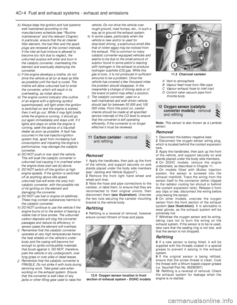
disconnect them (see illustration). Unscrew
the two nuts securing the canister mounting
bracket to the vehicle body.
Refitting
4Refitting is a reversal of removal, however
ensure correct fitment of hose and pipes.
12Oxygen sensor (catalytic
converter models) - removal
and refitting
3
Note: This sensor is also known as a Lambda
sensor.
Removal
1Disconnect the battery negative lead.
2Disconnect the oxygen sensor wiring plug,
which is located behind the coolant expansion
tank.
3Apply the handbrake, then jack up the front
of the vehicle, and support securely on axle
stands placed under the body side members.
4On DOHC models, remove the engine
undershield, as described in Chapter 11.
5On models fitted with Multec injection
system, the sensor is screwed into the
exhaust manifold. Trace the wiring from the
sensor itself to the connector (either clipped
to the radiator cooling fan shroud or behind
the coolant expansion tank). Release it from
any clips or ties; disconnect the wiring before
unscrewing the sensor.
6On other models, unscrew the oxygen
sensor from the front section of the exhaust
system (see illustration). It is advisable to
wear gloves, as the exhaust system will be
extremely hot.
7Withdraw the oxygen sensor and its wiring,
taking care not to burn the wiring on the
exhaust system. If the sensor is to be re-used,
take care that the sealing ring is not lost, and
that the sensor is not dropped.
Refitting
8If a new sensor is being fitted, it will be
supplied with the threads coated in a special
grease to prevent it seizing in the exhaust
system.
9If the original sensor is being refitted,
ensure that the screw thread is clean. Coat
the thread with a lithium based copper grease
(i.e. Vauxhall Part No. 90295397).
10Refitting is a reversal of removal. Check
the exhaust system for leakage when the
engine is re-started.
4C•4Fuel and exhaust systems - exhaust and emissions
12.6 Oxygen sensor location in front
section of exhaust system - DOHC models
11.3 Charcoal canister
A Vent to atmosphere
B Vapour feed hose from filler pipe
C Vapour exhaust hose to inlet tract
D Control valve vacuum pipe from
throttle body
Page 182 of 525
At the same time, check the general
condition of the CV joints themselves by first
holding the driveshaft and attempting to
rotate the wheel. Repeat this check by holding
the inner joint and attempting to rotate the
driveshaft. Any appreciable movement
indicates wear in the joints, wear in the
driveshaft splines, or a loose driveshaft
retaining nut.
7Automatic transmission fluid
level check
2
Note: The transmission fluid level can be
checked either when it is cold (only below
35ºC (100ºF) outside temperature) or when it is
fully warmed up to normal operating
temperature (after driving for a distance of
approximately 12 miles/20 km). Since the fluid
level must be checked with the engine
running, ensure that the vehicle is parked on
level ground with the handbrake firmly applied
before leaving the driver’s seat. Be careful to
keep loose clothing, long hair, etc., well clear
of hot or moving components when working
under the bonnet
Transmission cold
1Park the vehicle on level ground and apply
the handbrake firmly. With the engine running
at no more than idle speed and your foot
firmly on the brake pedal, move the selector
lever through all positions, ending in position
“P”. Allow the engine to idle for one minute,
then check the level within two minutes.
2With the engine still idling and position “P”
still selected, open the bonnet and withdraw
the transmission dipstick from the filler tube
located in the front of the transmission casing,
at the left-hand end of the engine.
3Note the fluid’s condition (see below), then
wipe clean the dipstick using a clean,
non-fluffy rag, insert it fully back into the tube
and withdraw it again.
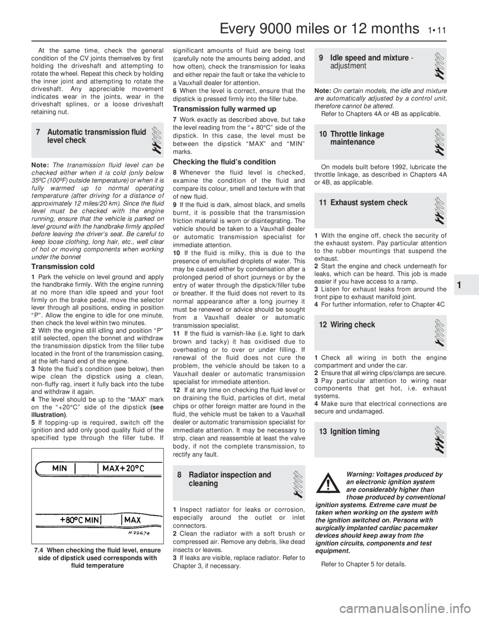
4The level should be up to the “MAX” mark
on the “+20°C” side of the dipstick (see
illustration).
5If topping-up is required, switch off the
ignition and add only good quality fluid of the
specified type through the filler tube. Ifsignificant amounts of fluid are being lost
(carefully note the amounts being added, and
how often), check the transmission for leaks
and either repair the fault or take the vehicle to
a Vauxhall dealer for attention.
6When the level is correct, ensure that the
dipstick is pressed firmly into the filler tube.
Transmission fully warmed up
7Work exactly as described above, but take
the level reading from the “+ 80°C” side of the
dipstick. In this case, the level must be
between the dipstick “MAX” and “MIN”
marks.
Checking the fluid’s condition
8Whenever the fluid level is checked,
examine the condition of the fluid and
compare its colour, smell and texture with that
of new fluid.
9If the fluid is dark, almost black, and smells
burnt, it is possible that the transmission
friction material is worn or disintegrating. The
vehicle should be taken to a Vauxhall dealer
or automatic transmission specialist for
immediate attention.
10If the fluid is milky, this is due to the
presence of emulsified droplets of water. This
may be caused either by condensation after a
prolonged period of short journeys or by the
entry of water through the dipstick/filler tube
or breather. If the fluid does not revert to its
normal appearance after a long journey it
must be renewed or advice should be sought
from a Vauxhall dealer or automatic
transmission specialist.
11If the fluid is varnish-like (i.e. light to dark
brown and tacky) it has oxidised due to
overheating or to over or under filling. If
renewal of the fluid does not cure the
problem, the vehicle should be taken to a
Vauxhall dealer or automatic transmission
specialist for immediate attention.
12If at any time on checking the fluid level or
on draining the fluid, particles of dirt, metal
chips or other foreign matter are found in the
fluid, the vehicle must be taken to a Vauxhall
dealer or automatic transmission specialist for
immediate attention. It may be necessary to
strip, clean and reassemble at least the valve
body, if not the complete transmission, to
rectify any fault.
8Radiator inspection and
cleaning
1
1Inspect radiator for leaks or corrosion,
especially around the outlet or inlet
connectors.
2Clean the radiator with a soft brush or
compressed air. Remove any debris, like dead
insects or leaves.
3If leaks are visible, replace radiator. Refer to
Chapter 3, if necessary.
9Idle speed and mixture -
adjustment
2
Note: On certain models, the idle and mixture
are automatically adjusted by a control unit,
therefore cannot be altered.
Refer to Chapters 4A or 4B as applicable.
10Throttle linkage
maintenance
2
On models built before 1992, lubricate the
throttle linkage, as described in Chapters 4A
or 4B, as applicable.
11Exhaust system check
2
1With the engine off, check the security of
the exhaust system. Pay particular attention
to the rubber mountings that suspend the
exhaust.
2Start the engine and check underneath for
leaks, which can be heard. This job is made
easier if you have access to a ramp.
3Listen for exhaust leaks from around the
front pipe to exhaust manifold joint.
4For further information, refer to Chapter 4C
12Wiring check
1
1Check all wiring in both the engine
compartment and under the car.
2Ensure that all wiring clips/clamps are secure.
3Pay particular attention to wiring near
components that get hot, i.e. exhaust
systems.
4Make sure that electrical connections are
secure and undamaged.
13Ignition timing
3
Refer to Chapter 5 for details.
Every 9000 miles or 12 months 1•11
7.4 When checking the fluid level, ensure
side of dipstick used corresponds with
fluid temperature
1
Warning: Voltages produced by
an electronic ignition system
are considerably higher than
those produced by conventional
ignition systems. Extreme care must be
taken when working on the system with
the ignition switched on. Persons with
surgically implanted cardiac pacemaker
devices should keep away from the
ignition circuits, components and test
equipment.
Page 223 of 525
25Flywheel -removal, inspection
and refitting
4
Note: New flywheel securing bolts must he
used on refitting. Certain models are fitted
with a ‘Pot type’ flywheel. Although, it has a
deeply recessed surface for the clutch disc,
the operations below are the same.
Removal
1If not already done, remove the clutch,
(Chapter 6), and the starter motor, (Chapter 5).
2If the engine is in the vehicle, remove the
clutch release bearing and its guide sleeve, as
described in Chapter 6.
3Although the flywheel bolt holes are offset
so that the flywheel can only be fitted in one
position, it will make refitting easier if
alignment marks are made between the
flywheel and the end of the crankshaft.
4Prevent the flywheel from turning by
jamming the ring gear teeth using a large
screwdriver or similar tool. Access is most
easily obtained through the starter motor
aperture if the engine is in the vehicle.
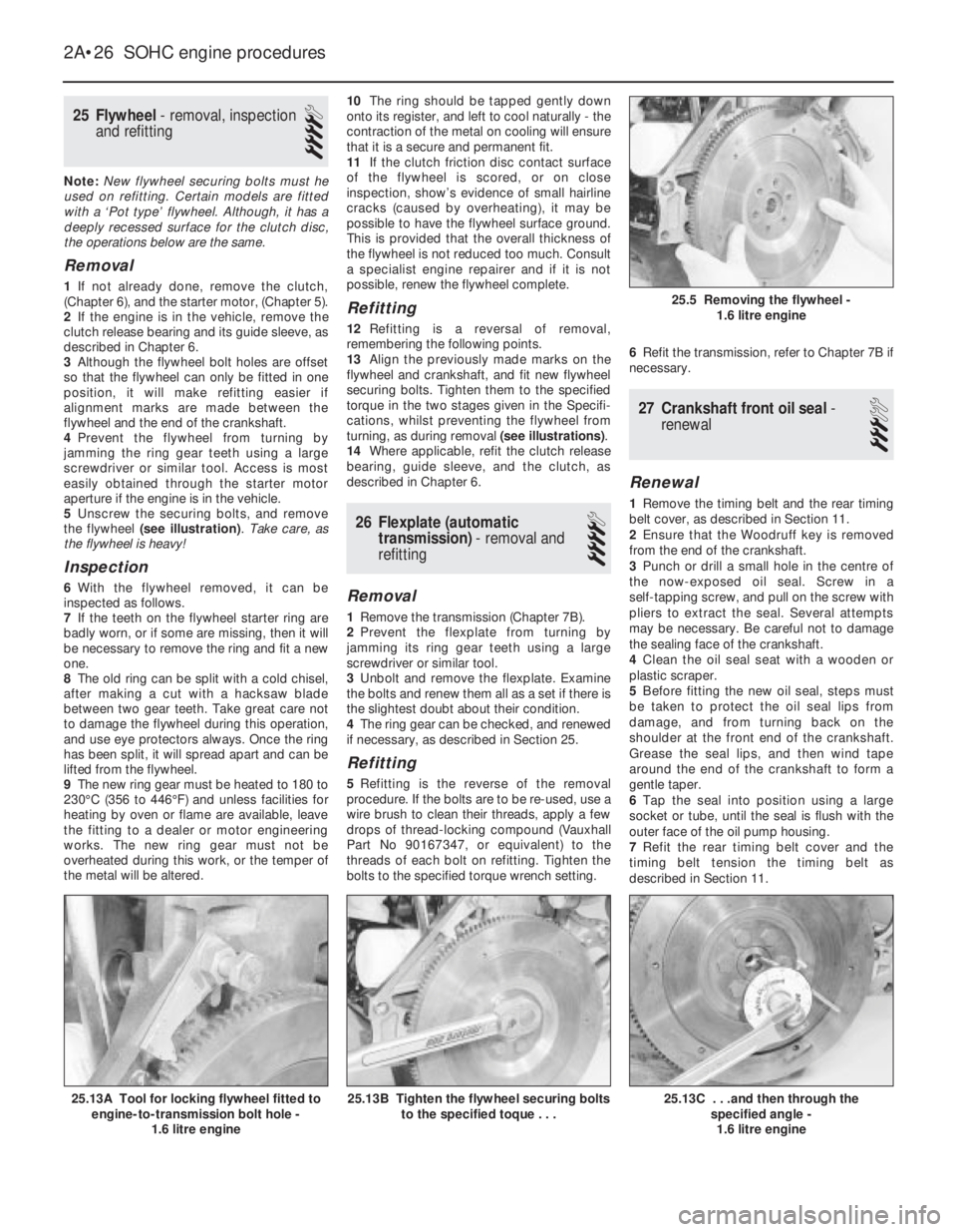
5Unscrew the securing bolts, and remove
the flywheel (see illustration). Take care, as
the flywheel is heavy!
Inspection
6With the flywheel removed, it can be
inspected as follows.
7If the teeth on the flywheel starter ring are
badly worn, or if some are missing, then it will
be necessary to remove the ring and fit a new
one.
8The old ring can be split with a cold chisel,
after making a cut with a hacksaw blade
between two gear teeth. Take great care not
to damage the flywheel during this operation,
and use eye protectors always. Once the ring
has been split, it will spread apart and can be
lifted from the flywheel.
9The new ring gear must be heated to 180 to
230°C (356 to 446°F) and unless facilities for
heating by oven or flame are available, leave
the fitting to a dealer or motor engineering
works. The new ring gear must not be
overheated during this work, or the temper of
the metal will be altered.10The ring should be tapped gently down
onto its register, and left to cool naturally -the
contraction of the metal on cooling will ensure
that it is a secure and permanent fit.
11If the clutch friction disc contact surface
of the flywheel is scored, or on close
inspection, show’s evidence of small hairline
cracks (caused by overheating), it may be
possible to have the flywheel surface ground.
This is provided that the overall thickness of
the flywheel is not reduced too much. Consult
a specialist engine repairer and if it is not
possible, renew the flywheel complete.
Refitting
12Refitting is a reversal of removal,
remembering the following points.
13Align the previously made marks on the
flywheel and crankshaft, and fit new flywheel
securing bolts. Tighten them to the specified
torque in the two stages given in the Specifi-
cations, whilst preventing the flywheel from
turning, as during removal (see illustrations).
14Where applicable, refit the clutch release
bearing, guide sleeve, and the clutch, as
described in Chapter 6.
26Flexplate (automatic
transmission) -removal and
refitting
4
Removal
1Remove the transmission (Chapter 7B).
2Prevent the flexplate from turning by
jamming its ring gear teeth using a large
screwdriver or similar tool.
3Unbolt and remove the flexplate. Examine
the bolts and renew them all as a set if there is
the slightest doubt about their condition.
4The ring gear can be checked, and renewed
if necessary, as described in Section 25.
Refitting
5Refitting is the reverse of the removal
procedure. If the bolts are to be re-used, use a
wire brush to clean their threads, apply a few
drops of thread-locking compound (Vauxhall
Part No 90167347, or equivalent) to the
threads of each bolt on refitting. Tighten the
bolts to the specified torque wrench setting.6Refit the transmission, refer to Chapter 7B if
necessary.
27Crankshaft front oil seal -
renewal
3
Renewal
1Remove the timing belt and the rear timing
belt cover, as described in Section 11.
2Ensure that the Woodruff key is removed
from the end of the crankshaft.
3Punch or drill a small hole in the centre of
the now-exposed oil seal. Screw in a
self-tapping screw, and pull on the screw with
pliers to extract the seal. Several attempts
may be necessary. Be careful not to damage
the sealing face of the crankshaft.
4Clean the oil seal seat with a wooden or
plastic scraper.
5Before fitting the new oil seal, steps must
be taken to protect the oil seal lips from
damage, and from turning back on the
shoulder at the front end of the crankshaft.
Grease the seal lips, and then wind tape
around the end of the crankshaft to form a
gentle taper.
6Tap the seal into position using a large
socket or tube, until the seal is flush with the
outer face of the oil pump housing.
7Refit the rear timing belt cover and the
timing belt tension the timing belt as
described in Section 11.
2A•26SOHC engine procedures
25.13C . . .and then through the
specified angle -
1.6 litre engine25.13B Tighten the flywheel securing bolts
to the specified toque . . .25.13A Tool for locking flywheel fitted to
engine-to-transmission bolt hole -
1.6 litre engine
25.5 Removing the flywheel -
1.6 litre engine
Page 251 of 525
Engine
m mEngine fails to rotate when attempting to start
m mEngine rotates, but will not start
m mEngine difficult to start when cold
m mEngine difficult to start when hot
m mStarter motor noisy or excessively rough in engagement
m mEngine starts, but stops immediately
m mEngine idles erratically
m mEngine misfires at idle speed
m mEngine misfires throughout the driving speed range
m mEngine hesitates on acceleration
m mEngine stalls
m mEngine lacks power
m mEngine backfires
m mOil pressure warning light illuminated with engine running
m mEngine runs-on after switching off
m mEngine noises
Cooling system
m
mOverheating
m mOvercooling
m mExternal coolant leakage
m mInternal coolant leakage
m mCorrosion
Fuel and exhaust systems
m
mExcessive fuel consumption
m mFuel leakage and/or fuel odour
m mExcessive noise or fumes from exhaust system
Clutch
m
mPedal travels to floor - no pressure or very little resistance
m mClutch fails to disengage (unable to select gears)
m mClutch slips (engine speed increases, with no increase in vehicle
speed)
m mJudder as clutch is engaged
m mNoise when depressing or releasing clutch pedal
Manual transmission
m
mNoisy in neutral with engine running
m mNoisy in one particular gear
m mDifficulty engaging gears
m mJumps out of gear
m mVibration
m mLubricant leaks
Automatic transmission
m
mFluid leakage
m mTransmission fluid brown, or has burned smell
m mGeneral gear selection problems
m mTransmission will not downshift (kickdown) with accelerator fully
depressed
m mEngine will not start in any gear, or starts in gears other than Park
or Neutral
m mTransmission slips, shifts roughly, is noisy, or has no drive in
forward or reverse gears
Driveshafts
m mClicking or knocking noise on turns (at slow speed on full-lock)
m mVibration when accelerating or decelerating
Braking system
m
mVehicle pulls to one side under braking
m mNoise (grinding or high-pitched squeal) when brakes applied
m mExcessive brake pedal travel
m mBrake pedal feels spongy when depressed
m mExcessive brake pedal effort required to stop vehicle
m mJudder felt through brake pedal or steering wheel when braking
m mBrakes binding
m mRear wheels locking under normal braking
Suspension and steering systems
m
mVehicle pulls to one side
m mWheel wobble and vibration
m mExcessive pitching and/or rolling around corners, or during
braking
m mWandering or general instability
m mExcessively stiff steering
m mExcessive play in steering
m mLack of power assistance
m mTyre wear excessive
Electrical system
m
mBattery will not hold a charge for more than a few days
m mIgnition/no-charge warning light remains illuminated with engine
running
m mIgnition/no-charge warning light fails to come on
m mLights inoperative
m mInstrument readings inaccurate or erratic
m mHorn inoperative, or unsatisfactory in operation
m mWindscreen/tailgate wipers inoperative, or unsatisfactory in
operation
m mWindscreen/tailgate washers inoperative, or unsatisfactory in
operation
m mElectric windows inoperative, or unsatisfactory in operation
m mCentral locking system inoperative, or unsatisfactory in operation
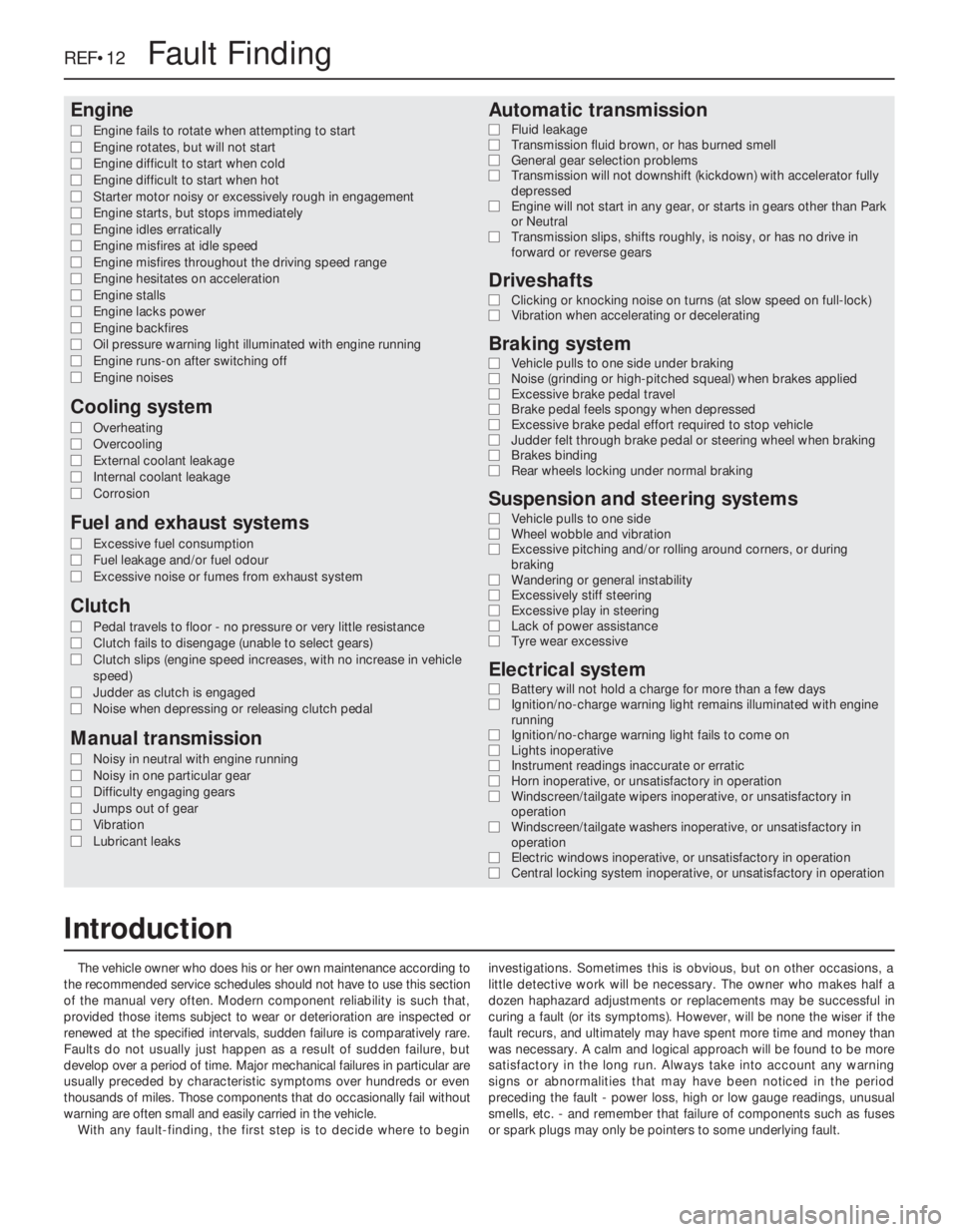
The vehicle owner who does his or her own maintenance according to
the recommended service schedules should not have to use this section
of the manual very often. Modern component reliability is such that,
provided those items subject to wear or deterioration are inspected or
renewed at the specified intervals, sudden failure is comparatively rare.
Faults do not usually just happen as a result of sudden failure, but
develop over a period of time. Major mechanical failures in particular are
usually preceded by characteristic symptoms over hundreds or even
thousands of miles. Those components that do occasionally fail without
warning are often small and easily carried in the vehicle.
With any fault-finding, the first step is to decide where to begininvestigations. Sometimes this is obvious, but on other occasions, a
little detective work will be necessary. The owner who makes half a
dozen haphazard adjustments or replacements may be successful in
curing a fault (or its symptoms). However, will be none the wiser if the
fault recurs, and ultimately may have spent more time and money than
was necessary. A calm and logical approach will be found to be more
satisfactory in the long run. Always take into account any warning
signs or abnormalities that may have been noticed in the period
preceding the fault - power loss, high or low gauge readings, unusual
smells, etc. - and remember that failure of components such as fuses
or spark plugs may only be pointers to some underlying fault.
REF•12Fault Finding
Introduction
Page 254 of 525
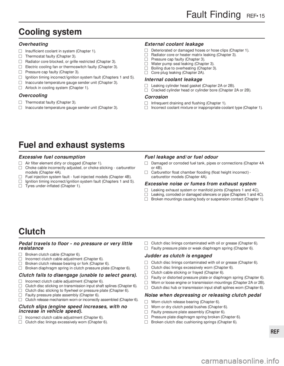
Excessive fuel consumption
MAir filter element dirty or clogged (Chapter 1).
MChoke cable incorrectly adjusted, or choke sticking - carburettor
models (Chapter 4A).
MFuel injection system fault - fuel-injected models (Chapter 4B).
MIgnition timing incorrect/ignition system fault (Chapters 1 and 5).
MTyres under-inflated (Chapter 1).
Fuel leakage and/or fuel odour
MDamaged or corroded fuel tank, pipes or connections (Chapter 4A
or 4B).
MCarburettor float chamber flooding (float height incorrect) -
carburettor models (Chapter 4A).
Excessive noise or fumes from exhaust system
MLeaking exhaust system or manifold joints (Chapters 1 and 4C).
MLeaking, corroded or damaged silencers or pipe (Chapters 1 and 4C).
MBroken mountings causing body or suspension contact (Chapter 1).
Pedal travels to floor - no pressure or very little
resistance
MBroken clutch cable (Chapter 6).
MIncorrect clutch cable adjustment (Chapter 6).
MBroken clutch release bearing or fork (Chapter 6).
MBroken diaphragm spring in clutch pressure plate (Chapter 6).
Clutch fails to disengage (unable to select gears).
MIncorrect clutch cable adjustment (Chapter 6).
MClutch disc sticking on transmission input shaft splines (Chapter 6).
MClutch disc sticking to flywheel or pressure plate (Chapter 6).
MFaulty pressure plate assembly (Chapter 6).
MClutch release mechanism worn or incorrectly assembled (Chapter 6).
Clutch slips (engine speed increases, with no
increase in vehicle speed).
MIncorrect clutch cable adjustment (Chapter 6).
MClutch disc linings excessively worn (Chapter 6).MClutch disc linings contaminated with oil or grease (Chapter 6).
MFaulty pressure plate or weak diaphragm spring (Chapter 6).
Judder as clutch is engaged
MClutch disc linings contaminated with oil or grease (Chapter 6).
MClutch disc linings excessively worn (Chapter 6).
MClutch cable sticking or frayed (Chapter 6).
MFaulty or distorted pressure plate or diaphragm spring (Chapter 6).
MWorn or loose engine or transmission mountings (Chapter 2A or 2B).
MClutch disc hub or transmission input shaft splines worn (Chapter 6).
Noise when depressing or releasing clutch pedal
MWorn clutch release bearing (Chapter 6).
MWorn or dry clutch pedal bushes (Chapter 6).
MFaulty pressure plate assembly (Chapter 6).
MPressure plate diaphragm spring broken (Chapter 6).
MBroken clutch disc cushioning springs (Chapter 6).
Fault Finding REF•15
REF
Overheating
MInsufficient coolant in system (Chapter 1).
MThermostat faulty (Chapter 3).
MRadiator core blocked, or grille restricted (Chapter 3).
MElectric cooling fan or thermoswitch faulty (Chapter 3).
MPressure cap faulty (Chapter 3).
MIgnition timing incorrect/ignition system fault (Chapters 1 and 5).
MInaccurate temperature gauge sender unit (Chapter 3).
MAirlock in cooling system (Chapter 1).
Overcooling
MThermostat faulty (Chapter 3).
MInaccurate temperature gauge sender unit (Chapter 3).
External coolant leakage
MDeteriorated or damaged hoses or hose clips (Chapter 1).
MRadiator core or heater matrix leaking (Chapter 3).
MPressure cap faulty (Chapter 3).
MWater pump seal leaking (Chapter 3).
MBoiling due to overheating (Chapter 3).
MCore plug leaking (Chapter 2A).
Internal coolant leakage
MLeaking cylinder head gasket (Chapter 2A or 2B).
MCracked cylinder head or cylinder bore (Chapter 2A or 2B).
Corrosion
MInfrequent draining and flushing (Chapter 1).
MIncorrect coolant mixture or inappropriate coolant type (Chapter 1).
Cooling system
Clutch
Fuel and exhaust systems