glove box OPEL CALIBRA 1988 Service Repair Manual
[x] Cancel search | Manufacturer: OPEL, Model Year: 1988, Model line: CALIBRA, Model: OPEL CALIBRA 1988Pages: 525, PDF Size: 58.26 MB
Page 21 of 525
Refitting
10Refitting is a reversal of removal.
Fuel and temperature gauge
assembly -“high series” models
11The procedure is as described in
paragraphs 7 to 10 inclusive, except that the
gauge assembly is secured by four nuts.
Tachometer
12The procedure is as described in
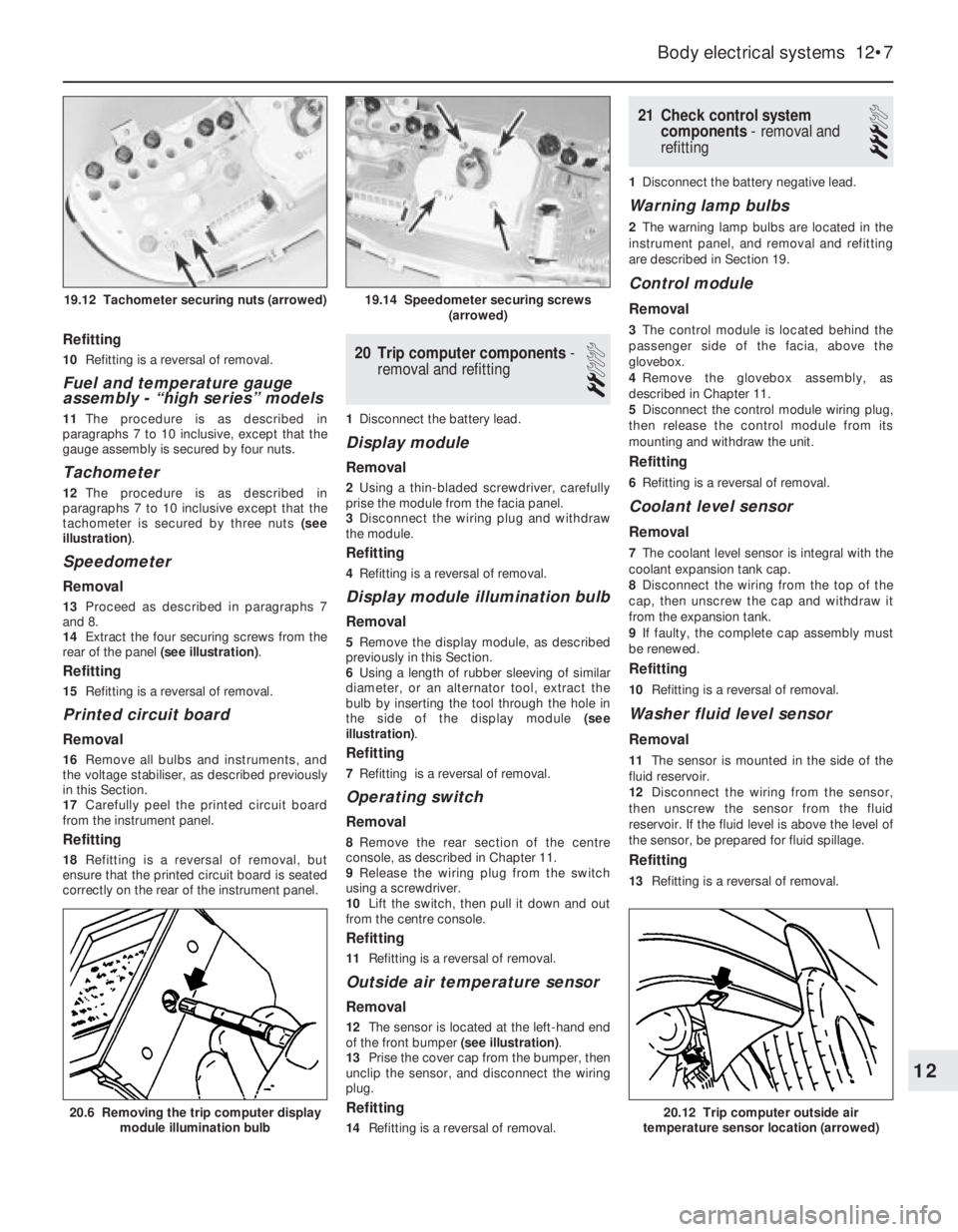
paragraphs 7 to 10 inclusive except that the
tachometer is secured by three nuts (see
illustration).
Speedometer
Removal
13Proceed as described in paragraphs 7
and 8.
14Extract the four securing screws from the
rear of the panel (see illustration).
Refitting
15Refitting is a reversal of removal.
Printed circuit board
Removal
16Remove all bulbs and instruments, and
the voltage stabiliser, as described previously
in this Section.
17Carefully peel the printed circuit board
from the instrument panel.
Refitting
18Refitting is a reversal of removal, but
ensure that the printed circuit board is seated
correctly on the rear of the instrument panel.
20Trip computer components -
removal and refitting
2
1Disconnect the battery lead.
Display module
Removal
2Using a thin-bladed screwdriver, carefully
prise the module from the facia panel.
3Disconnect the wiring plug and withdraw
the module.
Refitting
4Refitting is a reversal of removal.
Display module illumination bulb
Removal
5Remove the display module, as described
previously in this Section.
6Using a length of rubber sleeving of similar
diameter, or an alternator tool, extract the
bulb by inserting the tool through the hole in
the side of the display module (see
illustration).
Refitting
7Refitting is a reversal of removal.
Operating switch
Removal
8Remove the rear section of the centre
console, as described in Chapter 11.
9Release the wiring plug from the switch
using a screwdriver.
10Lift the switch, then pull it down and out
from the centre console.
Refitting
11Refitting is a reversal of removal.
Outside air temperature sensor
Removal
12The sensor is located at the left-hand end
of the front bumper (see illustration).
13Prise the cover cap from the bumper, then
unclip the sensor, and disconnect the wiring
plug.
Refitting
14Refitting is a reversal of removal.
21Check control system
components - removal and
refitting
3
1Disconnect the battery negative lead.
Warning lamp bulbs
2The warning lamp bulbs are located in the
instrument panel, and removal and refitting
are described in Section 19.
Control module
Removal
3The control module is located behind the
passenger side of the facia, above the
glovebox.
4Remove the glovebox assembly, as
described in Chapter 11.
5Disconnect the control module wiring plug,
then release the control module from its
mounting and withdraw the unit.
Refitting
6Refitting is a reversal of removal.
Coolant level sensor
Removal
7The coolant level sensor is integral with the
coolant expansion tank cap.
8Disconnect the wiring from the top of the
cap, then unscrew the cap and withdraw it
from the expansion tank.
9If faulty, the complete cap assembly must
be renewed.
Refitting
10Refitting is a reversal of removal.
Washer fluid level sensor
Removal
11The sensor is mounted in the side of the
fluid reservoir.
12Disconnect the wiring from the sensor,
then unscrew the sensor from the fluid
reservoir. If the fluid level is above the level of
the sensor, be prepared for fluid spillage.
Refitting
13Refitting is a reversal of removal.
Body electrical systems 12•7
20.6 Removing the trip computer display
module illumination bulb20.12 Trip computer outside air
temperature sensor location (arrowed)
19.14 Speedometer securing screws
(arrowed)19.12 Tachometer securing nuts (arrowed)
12
Page 23 of 525
4Remove the courtesy lamp bulbs by
carefully prising it from its location using a
thin-bladed screwdriver. Where applicable,
the map reading lamp bulbs are a push fit in
the bulbholders.
Refitting
5Refitting is a reversal of removal.
Glovebox lamp
Removal
6Using a thin-bladed screwdriver, prise the
lamp from its location and disconnect the
wiring.
7Carefully prise the bulb from the lamp.
Refitting
8Refitting is a reversal of removal.
Luggage compartment,
underbonnet and kerb lamps
Removal
9Using a thin-bladed screwdriver, prise the
lamp from its location; disconnect the wiring.
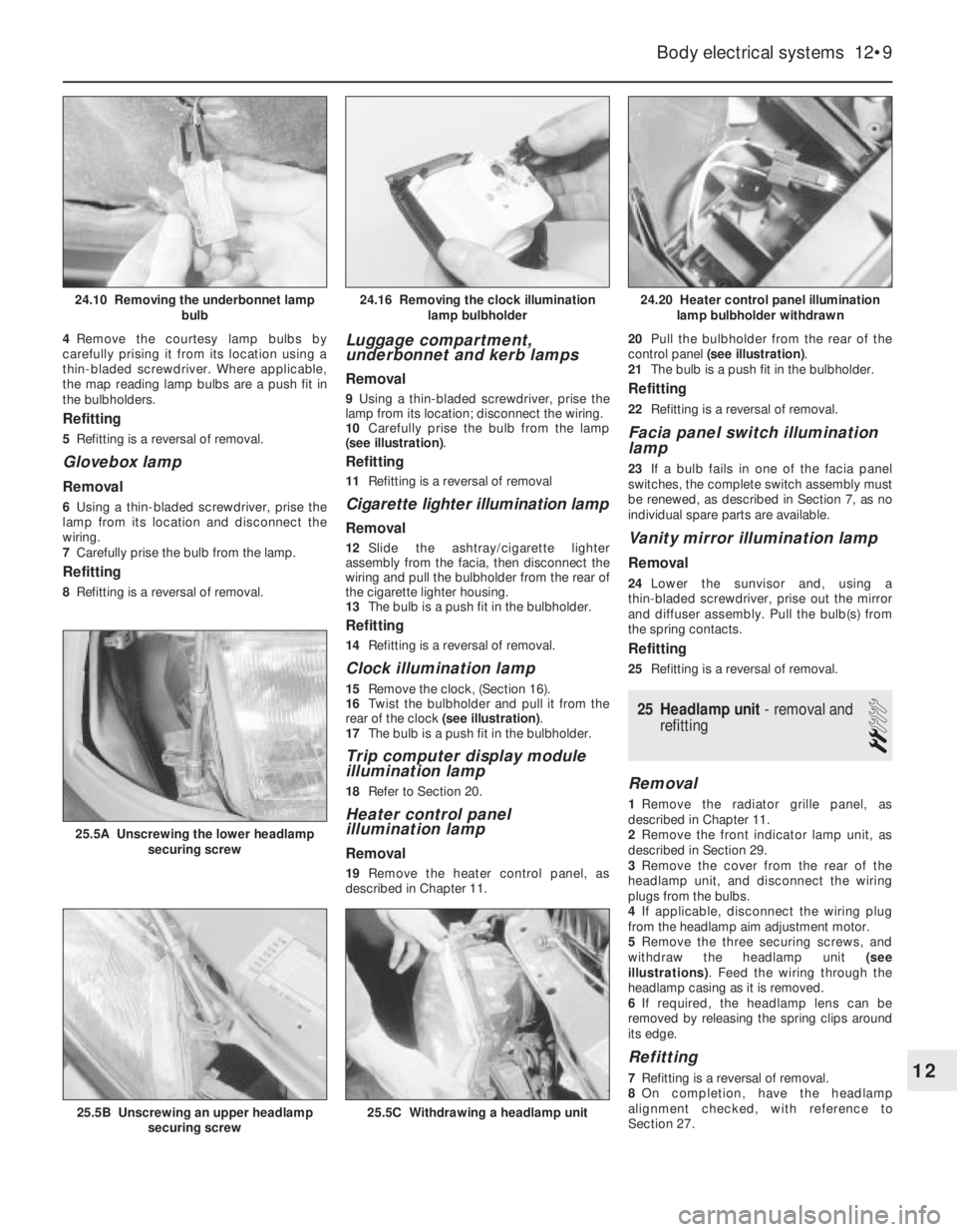
10Carefully prise the bulb from the lamp
(see illustration).
Refitting
11Refitting is a reversal of removal
Cigarette lighter illumination lamp
Removal
12Slide the ashtray/cigarette lighter
assembly from the facia, then disconnect the
wiring and pull the bulbholder from the rear of
the cigarette lighter housing.
13The bulb is a push fit in the bulbholder.
Refitting
14Refitting is a reversal of removal.
Clock illumination lamp
15Remove the clock, (Section 16).
16Twist the bulbholder and pull it from the
rear of the clock (see illustration).
17The bulb is a push fit in the bulbholder.
Trip computer display module
illumination lamp
18Refer to Section 20.
Heater control panel
illumination lamp
Removal
19Remove the heater control panel, as
described in Chapter 11. 20Pull the bulbholder from the rear of the
control panel (see illustration).
21The bulb is a push fit in the bulbholder.
Refitting
22Refitting is a reversal of removal.
Facia panel switch illumination
lamp
23If a bulb fails in one of the facia panel
switches, the complete switch assembly must
be renewed, as described in Section 7, as no
individual spare parts are available.
Vanity mirror illumination lamp
Removal
24Lower the sunvisor and, using a
thin-bladed screwdriver, prise out the mirror
and diffuser assembly. Pull the bulb(s) from
the spring contacts.
Refitting
25Refitting is a reversal of removal.
25Headlamp unit - removal and
refitting
2
Removal
1Remove the radiator grille panel, as
described in Chapter 11.
2Remove the front indicator lamp unit, as
described in Section 29.
3Remove the cover from the rear of the
headlamp unit, and disconnect the wiring
plugs from the bulbs.
4If applicable, disconnect the wiring plug
from the headlamp aim adjustment motor.
5Remove the three securing screws, and
withdraw the headlamp unit (see
illustrations). Feed the wiring through the
headlamp casing as it is removed.
6If required, the headlamp lens can be
removed by releasing the spring clips around
its edge.
Refitting
7Refitting is a reversal of removal.
8On completion, have the headlamp
alignment checked, with reference to
Section 27.
Body electrical systems 12•9
24.20 Heater control panel illumination
lamp bulbholder withdrawn
25.5C Withdrawing a headlamp unit25.5B Unscrewing an upper headlamp
securing screw
25.5A Unscrewing the lower headlamp
securing screw
24.16 Removing the clock illumination
lamp bulbholder24.10 Removing the underbonnet lamp
bulb
12
Page 24 of 525
27Headlamps -alignment
2
1Correct alignment of the headlamp beams
is most important, not only to ensure good
vision for the driver, but also to protect other
drivers from being dazzled.
2Accurate alignment should be carried out
using optical beam setting equipment.
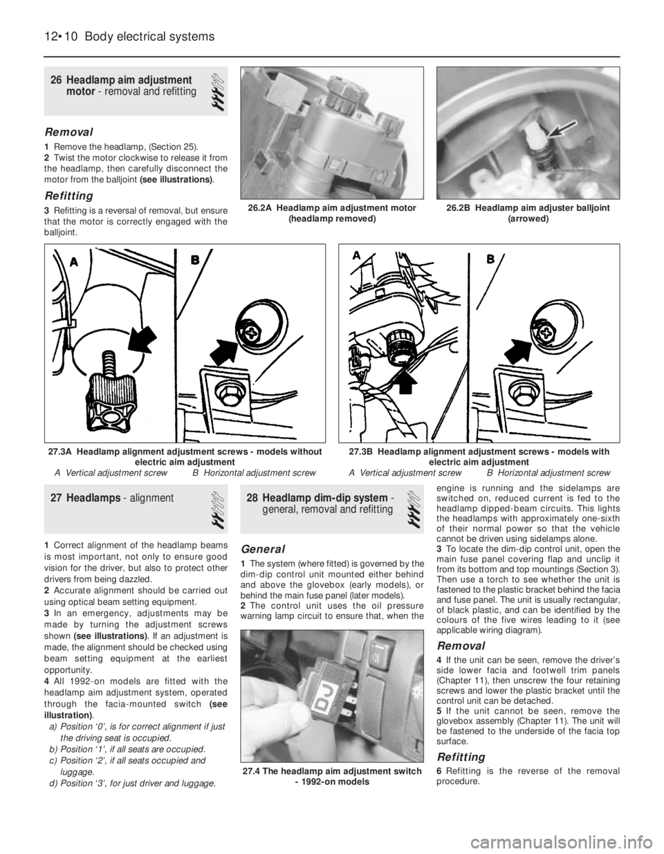
3In an emergency, adjustments may be
made by turning the adjustment screws
shown (see illustrations). If an adjustment is
made, the alignment should be checked using
beam setting equipment at the earliest
opportunity.
4All 1992-on models are fitted with the
headlamp aim adjustment system, operated
through the facia-mounted switch (see
illustration).
a)Position ‘0’, is for correct alignment if just
the driving seat is occupied.
b)Position ‘1’, if all seats are occupied.
c)Position ‘2’, if all seats occupied and
luggage.
d)Position ‘3’, for just driver and luggage.
28Headlamp dim-dip system -
general, removal and refitting
3
General
1The system (where fitted) is governed by the
dim-dip control unit mounted either behind
and above the glovebox (early models), or
behind the main fuse panel (later models).
2The control unit uses the oil pressure
warning lamp circuit to ensure that, when theengine is running and the sidelamps are
switched on, reduced current is fed to the
headlamp dipped-beam circuits. This lights
the headlamps with approximately one-sixth
of their normal power so that the vehicle
cannot be driven using sidelamps alone.
3To locate the dim-dip control unit, open the
main fuse panel covering flap and unclip it
from its bottom and top mountings (Section 3).
Then use a torch to see whether the unit is
fastened to the plastic bracket behind the facia
and fuse panel. The unit is usually rectangular,
of black plastic, and can be identified by the
colours of the five wires leading to it (see
applicable wiring diagram).
Removal
4If the unit can be seen, remove the driver’s
side lower facia and footwell trim panels
(Chapter 11), then unscrew the four retaining
screws and lower the plastic bracket until the
control unit can be detached.
5If the unit cannot be seen, remove the
glovebox assembly (Chapter 11). The unit will
be fastened to the underside of the facia top
surface.
Refitting
6Refitting is the reverse of the removal
procedure.
26Headlamp aim adjustment
motor - removal and refitting
3
Removal
1Remove the headlamp, (Section 25).
2Twist the motor clockwise to release it from
the headlamp, then carefully disconnect the
motor from the balljoint (see illustrations).
Refitting
3Refitting is a reversal of removal, but ensure
that the motor is correctly engaged with the
balljoint.
12•10Body electrical systems
26.2A Headlamp aim adjustment motor
(headlamp removed)
27.4 The headlamp aim adjustment switch
- 1992-on models
27.3B Headlamp alignment adjustment screws - models with
electric aim adjustment
A Vertical adjustment screw B Horizontal adjustment screw27.3A Headlamp alignment adjustment screws - models without
electric aim adjustment
A Vertical adjustment screw B Horizontal adjustment screw
26.2B Headlamp aim adjuster balljoint
(arrowed)
Page 34 of 525
56Airbag unit, drivers side -
removal and refitting
4
Note:On power steering models in particular,
it will be advantageous to jack up the front of
the car and support it on axle stands placed
under the body side members, so that the
steering wheel can be turned more easily.
Removal
1Disconnect the battery negative lead and
cover the battery terminal. Wait a minimum of 1
minute.
2With the steering wheel positioned in the
straight-ahead position, turn it 90°clockwise
so that the left-hand spoke is accessible from
the rear.
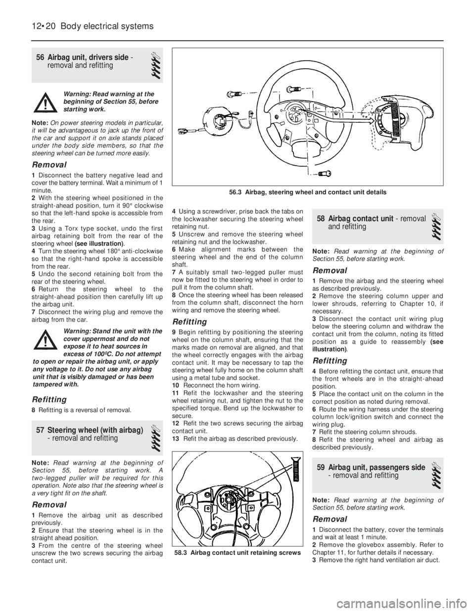
3Using a Torx type socket, undo the first
airbag retaining bolt from the rear of the
steering wheel (see illustration).
4Turn the steering wheel 180°anti-clockwise
so that the right-hand spoke is accessible
from the rear.
5Undo the second retaining bolt from the
rear of the steering wheel.
6Return the steering wheel to the
straight-ahead position then carefully lift up
the airbag unit.
7Disconnect the wiring plug and remove the
airbag from the car.
Refitting
8Refitting is a reversal of removal.
57Steering wheel (with airbag)
-removal and refitting
4
Note: Read warning at the beginning of
Section 55, before starting work. A
two-legged puller will be required for this
operation. Note also that the steering wheel is
a very tight fit on the shaft.
Removal
1Remove the airbag unit as described
previously.
2Ensure that the steering wheel is in the
straight ahead position.
3From the centre of the steering wheel
unscrew the two screws securing the airbag
contact unit.4Using a screwdriver, prise back the tabs on
the lockwasher securing the steering wheel
retaining nut.
5Unscrew and remove the steering wheel
retaining nut and the lockwasher.
6Make alignment marks between the
steering wheel and the end of the column
shaft.
7A suitably small two-legged puller must
now be fitted to the steering wheel in order to
pull it from the column shaft.
8Once the steering wheel has been released
from the column shaft, disconnect the horn
wiring and remove the steering wheel.
Refitting
9Begin refitting by positioning the steering
wheel on the column shaft, ensuring that the
marks made on removal are aligned, and that
the wheel correctly engages with the airbag
contact unit. It may be necessary to tap the
steering wheel fully home on the column shaft
using a metal tube and socket.
10Reconnect the horn wiring.
11Refit the lockwasher and the steering
wheel retaining nut, and tighten the nut to the
specified torque. Bend up the lockwasher to
secure.
12Refit the two screws securing the airbag
contact unit.
13Refit the airbag as described previously.
58Airbag contact unit -removal
and refitting
4
Note: Read warning at the beginning of
Section 55, before starting work.
Removal
1Remove the airbag and the steering wheel
as described previously.
2Remove the steering column upper and
lower shrouds, referring to Chapter 10, if
necessary.
3Disconnect the contact unit wiring plug
below the steering column and withdraw the
contact unit from the column, noting its fitted
position as a guide to reassembly (see
illustration).
Refitting
4Before refitting the contact unit, ensure that
the front wheels are in the straight-ahead
position.
5Place the contact unit on the column in the
correct position as noted during removal.
6Route the wiring harness under the steering
column lock/ignition switch and connect the
wiring plug.
7Refit the steering column shrouds.
8Refit the steering wheel and airbag as
described previously.
59Airbag unit, passengers side
- removal and refitting
4
Note: Read warning at the beginning of
Section 55, before starting work.
Removal
1Disconnect the battery, cover the terminals
and wait at least 1 minute.
2Remove the glovebox assembly. Refer to
Chapter 11, for further details if necessary.
3Remove the right hand ventilation air duct.
12•20Body electrical systems
58.3 Airbag contact unit retaining screws
56.3 Airbag, steering wheel and contact unit details
Warning: Read warning at the
beginning of Section 55, before
starting work.
Warning: Stand the unit with the
cover uppermost and do not
expose it to heat sources in
excess of 100ºC. Do not attempt
to open or repair the airbag unit, or apply
any voltage to it. Do not use any airbag
unit that is visibly damaged or has been
tampered with.
Page 37 of 525
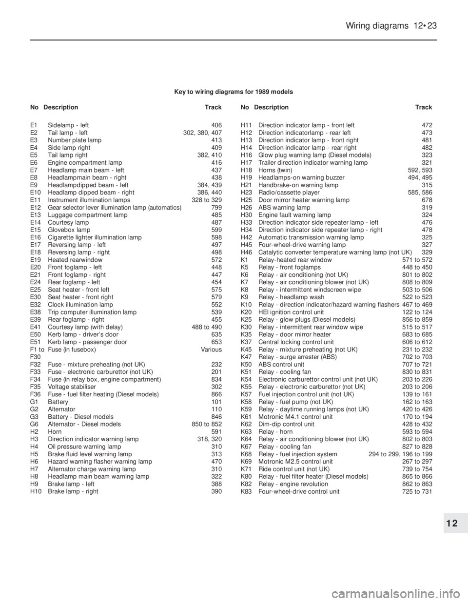
Wiring diagrams 12•23
12
Key to wiring diagrams for 1989 models
E1Sidelamp - left406
E2Tail lamp -left302, 380, 407
E3Number plate lamp413
E4Side lamp right409
E5Tail lamp right382, 410
E6Engine compartment lamp416
E7Headlamp main beam - left437
E8Headlampmain beam - right438
E9Headlampdipped beam - left384, 439
E10Headlamp dipped beam - right386, 440
E11Instrument illumination lamps328 to 329
E12Gear selector lever illumination lamp (automatics)799
E13Luggage compartment lamp485
E14Courtesy lamp487
E15Glovebox lamp599
E16Cigarette lighter illumination lamp598
E17Reversing lamp - left497
E18Reversing lamp - right498
E19Heated rearwindow572
E20Front foglamp -left448
E21Front foglamp - right447
E24Rear foglamp - left454
E25Seat heater -front left575
E30Seat heater - front right579
E32Clock illumination lamp552
E38Trip computer illumination lamp539
E39Rear foglamp - right455
E41Courtesy lamp (with delay)488 to 490
E50Kerb lamp - driver’s door635
E51Kerb lamp - passenger door653
F1 toFuse (in fusebox)Various
F30
F32Fuse - mixture preheating (not UK)232
F33Fuse - electronic carburettor (not UK)201
F34Fuse (in relay box, engine compartment)834
F35Voltage stabiliser302
F36Fuse - fuel filter heating (Diesel models)866
G1Battery101
G2Alternator110
G3Battery - Diesel models846
G6Alternator - Diesel models850 to 852
H2Horn591
H3Direction indicator warning lamp318, 320
H4Oil pressure warning lamp310
H5Brake fluid level warning lamp313
H6Hazard warning flasher warning lamp470
H7Alternator charge warning lamp310
H8Headlamp main beam warning lamp322
H9Brake lamp - left388
H10Brake lamp - right390H11Direction indicator lamp - front left472
H12Direction indicatorlamp - rear left473
H13Direction indicator lamp - front right481
H14Direction indicator lamp - rear right482
H16Glow plug warning lamp (Diesel models)323
H17Trailer direction indicator warning lamp321
H18Horns (twin)592, 593
H19Headlamps-on warning buzzer494, 495
H21Handbrake-on warning lamp315
H23Radio/cassette player585, 586
H25Door mirror heater warning lamp678
H26ABS warning lamp319
H30Engine fault warning lamp324
H33Direction indicator side repeater lamp - left476
H34Direction indicator side repeater lamp - right478
H42Automatic transmission warning lamp325
H45Four-wheel-drive warning lamp327
H46Catalytic converter temperature warning lamp (not UK)329
K1Relay-heated rear window571 to 572
K5Relay - front foglamps448 to 450
K6Relay - air conditioning (not UK)801 to 802
K7Relay - air conditioning blower (not UK)808 to 809
K8Relay - intermittent windscreen wipe503 to 506
K9Relay - headlamp wash522 to 523
K10Relay - direction indicator/hazard warning flashers467 to 469
K20HEI ignition control unit122 to 124
K25Relay - glow plugs (Diesel models)856 to 859
K30Relay - intermittent rear window wipe515 to 517
K35Relay - door mirror heater683 to 685
K37Central locking control unit606 to 612
K45Relay - mixture preheating (not UK)231 to 232
K47Relay - surge arrester (ABS)702 to 703
K50ABS control unit707 to 721
K51Relay - cooling fan830 to 831
K54Electronic carburettor control unit (not UK)203 to 226
K55Relay - electronic carburettor (not UK)203 to 206
K57Fuel injection control unit (not UK)139 to 161
K58Relay -fuel pump (not UK)162 to 163
K59Relay - daytime running lamps (not UK)420 to 426
K61Motronic M4.1 control unit170 to 194
K62Dim-dip control unit428 to 432
K63Relay - horn593 to 594
K64Relay - air conditioning blower (not UK)802 to 803
K67Relay -cooling fan827 to 828
K68Relay -fuel injection system294 to 299, 196 to 199
K69Motronic M2.5 control unit267 to 297
K71Ride control unit (not UK)739 to 754
K80Relay -fuel filter heater (Diesel models)865 to 866
K82Relay - engine revolution862 to 863
K83Four-wheel-drive control unit725 to 731 NoDescriptionTrackNoDescriptionTrack
Page 52 of 525
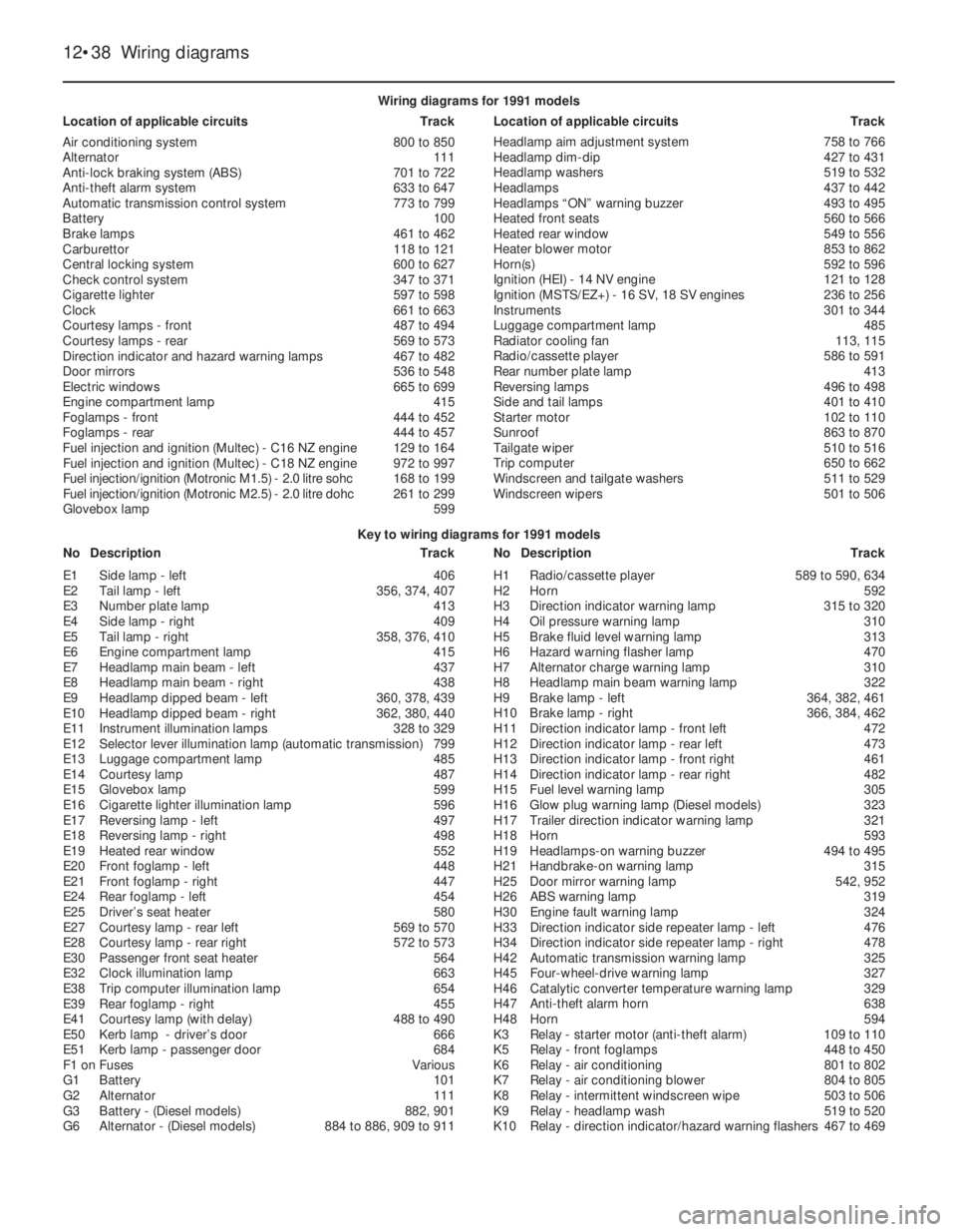
12•38Wiring diagrams
Key to wiring diagrams for 1991 models
NoDescriptionTrackNoDescriptionTrack Wiring diagrams for 1991 models
Location of applicable circuitsTrackLocation of applicable circuitsTrack
Air conditioning system800 to 850
Alternator111
Anti-lock braking system (ABS)701 to 722
Anti-theft alarm system633 to 647
Automatic transmission control system773 to 799
Battery100
Brake lamps461 to 462
Carburettor118 to 121
Central locking system600 to 627
Check control system347 to 371
Cigarette lighter597 to 598
Clock661 to 663
Courtesy lamps - front487 to 494
Courtesy lamps - rear569 to 573
Direction indicator and hazard warning lamps467 to 482
Door mirrors536 to 548
Electric windows665 to 699
Engine compartment lamp415
Foglamps - front444 to 452
Foglamps - rear444 to 457
Fuel injection and ignition (Multec) - C16NZ engine129 to 164
Fuel injection and ignition (Multec) - C18NZ engine972 to 997
Fuel injection/ignition (Motronic M1.5) - 2.0litre sohc 168 to 199
Fuel injection/ignition (Motronic M2.5) - 2.0litre dohc 261 to 299
Glovebox lamp599Headlamp aim adjustment system758 to 766
Headlamp dim-dip427 to 431
Headlamp washers519 to 532
Headlamps437 to 442
Headlamps “ON” warning buzzer493 to 495
Heated front seats560 to 566
Heated rear window549 to 556
Heater blower motor853 to 862
Horn(s)592 to 596
Ignition (HEI) - 14NV engine121 to 128
Ignition (MSTS/EZ+) - 16SV, 18 SV engines236 to 256
Instruments301 to 344
Luggage compartment lamp485
Radiator cooling fan113, 115
Radio/cassette player586 to 591
Rear number plate lamp413
Reversing lamps496 to 498
Side and tail lamps401 to 410
Starter motor102 to 110
Sunroof863 to 870
Tailgate wiper510 to 516
Trip computer650 to 662
Windscreen and tailgate washers511 to 529
Windscreen wipers501 to 506
E1Side lamp - left406
E2Tail lamp - left356, 374, 407
E3Number plate lamp413
E4Side lamp - right409
E5Tail lamp - right358, 376, 410
E6Engine compartment lamp415
E7Headlamp main beam - left437
E8Headlamp main beam - right438
E9Headlamp dipped beam - left360, 378, 439
E10Headlamp dipped beam - right362, 380, 440
E11Instrument illumination lamps328 to 329
E12Selector lever illumination lamp (automatic transmission)799
E13Luggage compartment lamp485
E14Courtesy lamp487
E15Glovebox lamp599
E16Cigarette lighter illumination lamp596
E17Reversing lamp - left497
E18Reversing lamp - right498
E19Heated rear window552
E20Front foglamp - left448
E21Front foglamp - right447
E24Rear foglamp - left454
E25Driver’s seat heater580
E27Courtesy lamp - rear left569 to 570
E28Courtesy lamp - rear right572 to 573
E30Passenger front seat heater564
E32Clock illumination lamp663
E38Trip computer illumination lamp654
E39Rear foglamp - right455
E41Courtesy lamp (with delay)488 to 490
E50Kerb lamp - driver’s door666
E51Kerb lamp - passenger door684
F1 onFusesVarious
G1Battery101
G2Alternator111
G3Battery - (Diesel models)882, 901
G6Alternator - (Diesel models)884 to 886, 909 to 911H1Radio/cassette player589 to 590, 634
H2Horn592
H3Direction indicator warning lamp315 to 320
H4Oil pressure warning lamp310
H5Brake fluid level warning lamp313
H6Hazard warning flasher lamp470
H7Alternator charge warning lamp310
H8Headlamp main beam warning lamp322
H9Brake lamp - left364, 382, 461
H10Brake lamp - right366, 384, 462
H11Direction indicator lamp - front left472
H12Direction indicator lamp - rear left473
H13Direction indicator lamp - front right461
H14Direction indicator lamp - rear right482
H15Fuel level warning lamp305
H16Glow plug warning lamp (Diesel models)323
H17Trailer direction indicator warning lamp321
H18Horn593
H19Headlamps-on warning buzzer494 to 495
H21Handbrake-on warning lamp315
H25Door mirror warning lamp542, 952
H26ABS warning lamp319
H30Engine fault warning lamp324
H33Direction indicator side repeater lamp - left476
H34Direction indicator side repeater lamp - right478
H42Automatic transmission warning lamp325
H45Four-wheel-drive warning lamp327
H46Catalytic converter temperature warning lamp329
H47Anti-theft alarm horn638
H48Horn594
K3Relay - starter motor (anti-theft alarm)109 to 110
K5Relay - front foglamps448 to 450
K6Relay - air conditioning801 to 802
K7Relay - air conditioning blower804 to 805
K8Relay - intermittent windscreen wipe503 to 506
K9Relay - headlamp wash519 to 520
K10Relay - direction indicator/hazard warning flashers467 to 469
Page 69 of 525
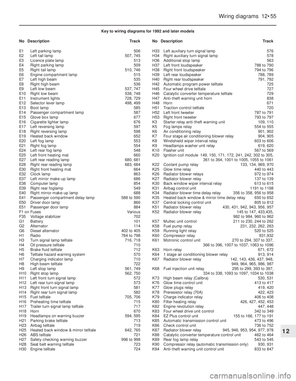
Wiring diagrams 12•55
12
Key to wiring diagrams for 1992 and later models
NoDescriptionTrackNoDescriptionTrack
E1Left parking lamp506
E2Left tail lamp507, 745
E3Licence plate lamp513
E4Right parking lamp509
E5Right tail lamp510, 746
E6Engine compartment lamp515
E7Left high beam 535
E8Right high beam536
E9Left low beam537, 747
E10Right low beam538, 748
E11Instrument lights728, 729
E12Selector lever lamp 498, 499
E13Boot lamp585
E14Passenger compartment lamp587
E15Glove box lamp677
E16Cigarette lighter lamp676
E17Left reversing lamp597
E18Right reversing lamp598
E19Heated back window652
E20Left fog lamp553
E21Right fog lamp554
E24Left rear fog lamp548
E25Left front heating mat660
E27Left rear reading lamp680, 681
E28Right rear reading lamp683, 684
E30Right front heating mat664
E32Clock lamp863
E37Left mirror make-up lamp686
E38Computer lamp854
E39Right rear foglamp549
E40Right mirror make-up lamp688
E41Passenger compartment delay lamp 588 to 590
E50Driver door lamp866
E51Passenger door lamp884
F1 onFusesVarious
F35Voltage stabilizer702
G1Battery101
G2Alternator114
G6Diesel alternator 402 to 405
H1Radio784 to 798
H3Turn signal lamp telltale716, 718
H4Oil pressure telltale710
H5Brake fluid telltale712
H6Telltale hazard warning system570
H7Charging indicator lamp710
H8High beam telltale722
H9Left stop lamp561, 749
H10Right stop lamp562, 750
H11Left front turn signal lamp572
H12Left rear turn signal lamp573
H13Right front turn signal lamp581
H14Right rear turn signal lamp582
H15Fuel telltale705, 706
H16Preheating time telltale715
H17Trailer turn signal lamp telltale717
H18Horn670
H19Headlamps on warning buzzer594, 595
H21Parking brake telltale713
H23Airbag telltale719
H25Heated back window & mirror telltale642, 765
H26ABS telltale721
H27Safety checking warning buzzer996 to 998
H28Seat belt warning telltale723
H30Engine telltale724H33Left auxiliary turn signal lamp576
H34Right auxiliary turn signal lamp578
H36Additional stop lamp563
H37Left front loudspeaker788 to 790
H38Right front loudspeaker794 to 796
H39Left rear loudspeaker788, 789
H40Right rear loudspeaker791, 792
H42Automatic program power telltale725
H45Four wheel drive telltale727
H46Catalytic converter temperature telltale729
H47Anti-theft warning unit horn838
H48Horn671
H51Traction control telltale720
H52Left front tweeter787 to 791
H53Right front tweeter793 to 797
K3Starter relay anti-theft warning unit109, 110
K5Fog lamps relay554 to 555
K6Air conditioning relay901, 902
K7Four stage air conditioning blower relay904, 905
K8Windshield wiper interval relay603 to 606
K9Headlamps washer unit relay619, 620
K10Flasher unit567 to 569
K20Ignition coil module149, 150, 171, 172, 241, 242, 302 to 305,
361 to 364, 1001 to 1005, 1055 to 1061
K22Coolant pump relay133, 134, 969, 970
K25Glow time relay440 to 443
K26Radiator blower relays972 to 974
K27Radiator blower relay137 to 139
K30Back window wiper interval relay613 to 615
K31Airbag control unit1191 to 1198
K34Radiator blower time delay relay356 to 358, 956 to 958
K35Heated back window & mirror time delay relay650 to 652
K37Central locking control unit805 to 812
K51Radiator blower relay430, 431, 942, 943, 956, 957
K52Radiator blower relay145 to 147, 433,435,
982 to 984, 960 to 962
K57Multec unit control211 to 230, 244 to 262
K58Fuel pump relay231, 232, 262, 263
K59Running light relay520 to 525
K60Compressor relay931,932
K61Motronic control unit270 to 294, 307 to 337,
366 to 396, 1007 to 1037, 1063 to 1096
K63Horn relay671, 672
K641 stage air conditioning blower relay913, 914
K67Radiator blower relay142, 143, 436, 437, 948,
949, 964, 965, 986, 987
K68Fuel injection unit relay295 to 299, 393 to 397,
334 to 338, 1093 to 1097, 1034 to 1038
K73High beam relay (Calibra)530, 531
K76Glow time control unit413 to 417
K77Glow plugs relay419, 420
K78Preresistor relay (70A)422, 423
K79Charge indicator relay406 to 408
K80Filter heating relay426, 427, 452, 453
K82Engine revolution relay447, 448
K83Four wheel drive unit control342 to 349
K84EZ Plus control unit155 to 166, 177 to 191
K85Automatic transmission control unit473 to 496
K86Check control unit736 to 752
K87Radiator blower relay945, 946, 953, 954, 977, 978
K88Catalytic converter temperature control unit462 to 464
K89Rear fog lamp relay543 to 545
K90Compressor relay (automatic transmission only)930, 931
K94Anti-theft warning unit control unit833 to 847
Page 121 of 525
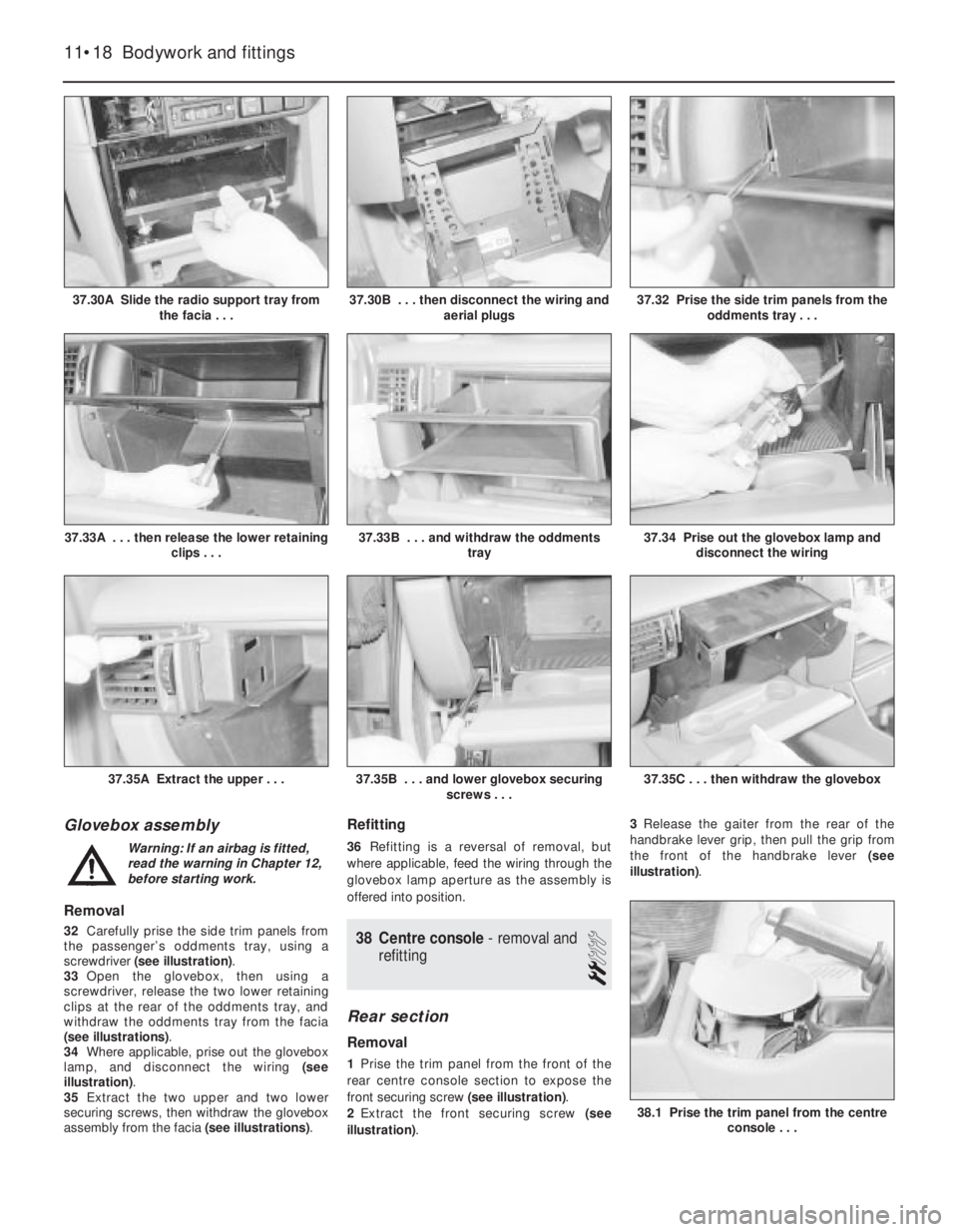
Glovebox assembly
Removal
32Carefully prise the side trim panels from
the passenger’s oddments tray, using a
screwdriver (see illustration).
33Open the glovebox, then using a
screwdriver, release the two lower retaining
clips at the rear of the oddments tray, and
withdraw the oddments tray from the facia
(see illustrations).
34Where applicable, prise out the glovebox
lamp, and disconnect the wiring (see
illustration).
35Extract the two upper and two lower
securing screws, then withdraw the glovebox
assembly from the facia (see illustrations).
Refitting
36Refitting is a reversal of removal, but
where applicable, feed the wiring through the
glovebox lamp aperture as the assembly is
offered into position.
38Centre console - removal and
refitting
2
Rear section
Removal
1Prise the trim panel from the front of the
rear centre console section to expose the
front securing screw (see illustration).
2Extract the front securing screw (see
illustration).3Release the gaiter from the rear of the
handbrake lever grip, then pull the grip from
the front of the handbrake lever (see
illustration).
11•18Bodywork and fittings
37.30A Slide the radio support tray from
the facia . . .37.32 Prise the side trim panels from the
oddments tray . . .
37.35C . . . then withdraw the glovebox37.35B . . . and lower glovebox securing
screws . . .37.35A Extract the upper . . .
37.34 Prise out the glovebox lamp and
disconnect the wiring37.33B . . . and withdraw the oddments
tray37.33A . . . then release the lower retaining
clips . . .
37.30B . . . then disconnect the wiring and
aerial plugs
38.1 Prise the trim panel from the centre
console . . .
Warning: If an airbag is fitted,
read the warning in Chapter 12,
before starting work.
Page 259 of 525
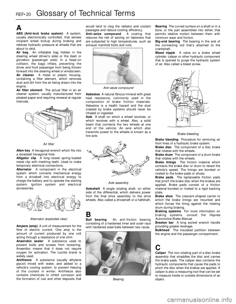
REF•20Glossary of Technical Terms
A
ABS (Anti-lock brake system)A system,
usually electronically controlled, that senses
incipient wheel lockup during braking and
relieves hydraulic pressure at wheels that are
about to skid.
Air bag An inflatable bag hidden in the
steering wheel (driver’s side) or the dash or
glovebox (passenger side). In a head-on
collision, the bags inflate, preventing the
driver and front passenger from being thrown
forward into the steering wheel or windscreen.
Air cleanerA metal or plastic housing,
containing a filter element, which removes
dust and dirt from the air being drawn into the
engine.
Air filter elementThe actual filter in an air
cleaner system, usually manufactured from
pleated paper and requiring renewal at regular
intervals.
Allen keyA hexagonal wrench which fits into
a recessed hexagonal hole.
Alligator clipA long-nosed spring-loaded
metal clip with meshing teeth. Used to make
temporary electrical connections.
AlternatorA component in the electrical
system which converts mechanical energy
from a drivebelt into electrical energy to
charge the battery and to operate the starting
system, ignition system and electrical
accessories.
Ampere (amp)A unit of measurement for the
flow of electric current. One amp is the
amount of current produced by one volt
acting through a resistance of one ohm.
Anaerobic sealerA substance used to
prevent bolts and screws from loosening.
Anaerobic means that it does not require
oxygen for activation. The Loctite brand is
widely used.
AntifreezeA substance (usually ethylene
glycol) mixed with water, and added to a
vehicle’s cooling system, to prevent freezing
of the coolant in winter. Antifreeze also
contains chemicals to inhibit corrosion and
the formation of rust and other deposits thatwould tend to clog the radiator and coolant
passages and reduce cooling efficiency.
Anti-seize compoundA coating that
reduces the risk of seizing on fasteners that
are subjected to high temperatures, such as
exhaust manifold bolts and nuts.
AsbestosA natural fibrous mineral with great
heat resistance, commonly used in the
composition of brake friction materials.
Asbestos is a health hazard and the dust
created by brake systems should never be
inhaled or ingested.
AxleA shaft on which a wheel revolves, or
which revolves with a wheel. Also, a solid
beam that connects the two wheels at one
end of the vehicle. An axle which also
transmits power to the wheels is known as a
live axle.
AxleshaftA single rotating shaft, on either
side of the differential, which delivers power
from the final drive assembly to the drive
wheels. Also called a driveshaft or a halfshaft.
BBall bearingAn anti-friction bearing
consisting of a hardened inner and outer race
with hardened steel balls between two races.BearingThe curved surface on a shaft or in a
bore, or the part assembled into either, that
permits relative motion between them with
minimum wear and friction.
Big-end bearingThe bearing in the end of
the connecting rod that’s attached to the
crankshaft.
Bleed nippleA valve on a brake wheel
cylinder, caliper or other hydraulic component
that is opened to purge the hydraulic system
of air. Also called a bleed screw.
Brake bleedingProcedure for removing air
from lines of a hydraulic brake system.
Brake discThe component of a disc brake
that rotates with the wheels.
Brake drumThe component of a drum brake
that rotates with the wheels.
Brake liningsThe friction material which
contacts the brake disc or drum to retard the
vehicle’s speed. The linings are bonded or
riveted to the brake pads or shoes.
Brake padsThe replaceable friction pads
that pinch the brake disc when the brakes are
applied. Brake pads consist of a friction
material bonded or riveted to a rigid backing
plate.
Brake shoeThe crescent-shaped carrier to
which the brake linings are mounted and
which forces the lining against the rotating
drum during braking.
Braking systemsFor more information on
braking systems, consult the Haynes
Automotive Brake Manual.
Breaker barA long socket wrench handle
providing greater leverage.
BulkheadThe insulated partition between
the engine and the passenger compartment.
CCaliperThe non-rotating part of a disc-brake
assembly that straddles the disc and carries
the brake pads. The caliper also contains the
hydraulic components that cause the pads to
pinch the disc when the brakes are applied. A
caliper is also a measuring tool that can be set
to measure inside or outside dimensions of an
object.
Brake bleeding
Bearing
Axle assembly
Anti-seize compound
Alternator (exploded view)
Air filter
Page 265 of 525
oil and filter renewal - 0•17, 1•2, 1•9
oil cooler - 2B•10
oil level - 0•12
oil pump - 2A•28, 2B•9
piston rings - 2A•30
piston/connecting rod - 2A•29
removal - 2A•8, 2B•3
SOHC - 2A•1 et seq
sump - 2A•27, 2B•9
timing belt - 2A•13, 2B•3, 2B•6
undershield - 11•13
valve lifters - 2A•24, 2B•9
valves - 2A•5, 2B•2
Environmental considerations- REF•4
Exhaust manifold- 4C•5
Exhaust system check- 1•11, 4C•5
Expansion tank- 3•5
FFan (radiator)- 3•5
Fault diagnosis- REF•12 et seq
automatic transmission - REF•12, REF•16
braking system - REF•12, REF•17
clutch - REF•12, REF•15
cooling system - REF•12, REF•15
driveshafts - REF•12, REF•16
electrical system - REF•12, REF•18
engine - REF•12, REF•13
fuel and exhaust systems - REF•12, REF•15
manual transmission - REF•12, REF•16
steering - REF•12, REF•17
suspension - REF•12, REF•17
Flexplate (automatic transmission)- 2A•26
Flushing (cooling system)- 3•2
Flywheel- 2A•26
Foglamp- 12•11
Fuel and exhaust (carburettor) systems-
4A•1 et seq
Fuel and exhaust (fuel injection) systems-
4B•1 et seq
Fuel and exhaust systems - emissions-
4C•1 et seq
Fuel and exhaust systems:
accelerator cable - 4A•5
accelerator pedal - 4A•5
air box - 4B•5
air cleaner - 1•3, 1•13, 4A•3, 4B•4
air pump/cut off valve - 4C•2
air temperature control - 4B•5
airflow meters - 4B•12
automatic choke - 4A•9
carbon canister - 4C•4
carburettor - 4A•5, 4A•11
catalytic converter - 4C•3
control unit - 4B•16
depressurising fuel system - 4B•5
EGR components - 4C•2
exhaust manifold - 4C•5
exhaust system check - 1•11, 4C•5
fault diagnosis - REF•12, REF•15
filler cap - 11•13
fuel filters - 1•3, 1•14, 4B•6
fuel flow damper - 4B•8
fuel injector(s) - 4B•13
fuel level sender unit - 4A•4, 4B•8
fuel pressure regulator - 4B•10
fuel pump - 4A•3, 4B•6fuel tank - 4A•4, 4B•7
fuel vapour separator - 4A•4
idle speed/mixture adjustment - 4A•7,
4A•12, 4B•9, 4B•11
inlet manifold - 4A•12, 4B•17
knock sensor - 4B•17
lambda sensor - 4C•4
manifolds - 4A•12, 4B•17, 4C•5
mixture (CO) - 4A•7, 4A•12, 4B•9
oxygen sensor - 4C•4
Pierburg 2E3 - 4A•5
potentiometer - 4B•12, 4B•16
throttle cable - 4A•5
throttle pedal - 4A•5
Fuses- 12•1, 12•3
GGear selector linkage- 7A•2
Gearbox - see Manual or Automatic
transmission
Gearbox oil- 0•17, 1•2, 1•15
Gearchange lever- 7A•3
Glass- 11•9
Glossary of technical terms- REF•20
Glove compartment- 11•18
HHandbrake adjustment- 9•18
Handbrake cables- 9•19
Handbrake lever- 9•20
Handles (door)- 11•7
Hazard warning switch- 12•4
Headlamp alignment- 12•10
Headlamp unit- 12•9
Headlining- 11•19
Heater blower motor switch- 12•4
Heater control panel- 3•6
Heater matrix- 3•7
Heating systems- 3•1 et seq
Horn- 12•8
Hose and fluid leak check- 0•9, 1•9
Hoses brake- 9•18
IIdle speed/mixture/adjustment- 4A•7,
4A•12, 4B•9, 4B•11
Ignition coil- 5•9
Ignition switch- 12•3
Ignition system- 5•2
Igniton timing- 5•2, 5•13
Indicator lamps- 12•11
Indicator switch- 12•4
Injector(s)- 4B•13
Inlet manifold- 4A•12, 4B•17
Input shaft (clutch) oil seal- 7A•4
Instrument panel- 12•6
Interior lamps- 12•8
Interior trim panels- 11•14
Introduction to the Vauxhall Cavalier- 0•4
JJacking and vehicle support- REF•5
Jump starting- 0•7
KKickdown switch - 7B•3
Knock sensor- 4B•17
LLambda sensor- 4C•4
Lamps- 12•8, 12•9
Leaks- 0•9, 1•9
Light switch- 12•4
Locks bonnet- 11•4
Locks door- 11•8
Locks tailgate- 11•6
Lubricants and fluids- 0•17
MMain and big-end bearings- 2A•31
Maintenance - see Routine maintenance
Maintenance schedule- 1•4
Manifolds- 4A•12, 4B•17, 4C•5
Manual transmission- 7A•1 et seq
differential bearing oil seals - 7A•3
fault diagnosis - REF•12, REF•16
gear selector linkage - 7A•2
gearbox oil - 0•17, 1•2, 1•15
gearchange lever - 7A•3
input shaft (clutch) oil seal - 7A•4
overhaul -7A•5
removal and refitting - 7A•4
reversing lamp switch - 7A•6
speedometer drive - 7A•6
Master cylinder (brake)- 9•13
Mirrors- 11•11
Mixture (CO)- 4A•7, 4B•9
MOT test checks- REF•8
Mountings (engine/transmission)- 2A•12,
2B•3
NNumber plate lamp- 12•11
OOil change- 0•17, 1•2, 1•9
Oil cooler- 2B•10
Oil filter- 1•2, 1•9
Oil pressure warning lamp switch- 12•5
Oil pump- 2A•28, 2B•9
Oil seals:
differential bearing - 7A•3
general - REF •4
camshaft - 2A•18, 2B•6
crankshaft - 2A•26, 2B•6, 2B•9
Oils- 0•17, 1•2
Open-circuit, finding - 12•2
Oxygen sensor- 4C•4
PPads (brake)- 9•4
Paintwork damage- 11•2
Parts- REF•3
Pedals
brake - 9•21
clutch - 6•3
throttle - 4A•5
REF•26Index