handbrake OPEL CALIBRA 1988 Service Repair Manual
[x] Cancel search | Manufacturer: OPEL, Model Year: 1988, Model line: CALIBRA, Model: OPEL CALIBRA 1988Pages: 525, PDF Size: 58.26 MB
Page 4 of 525
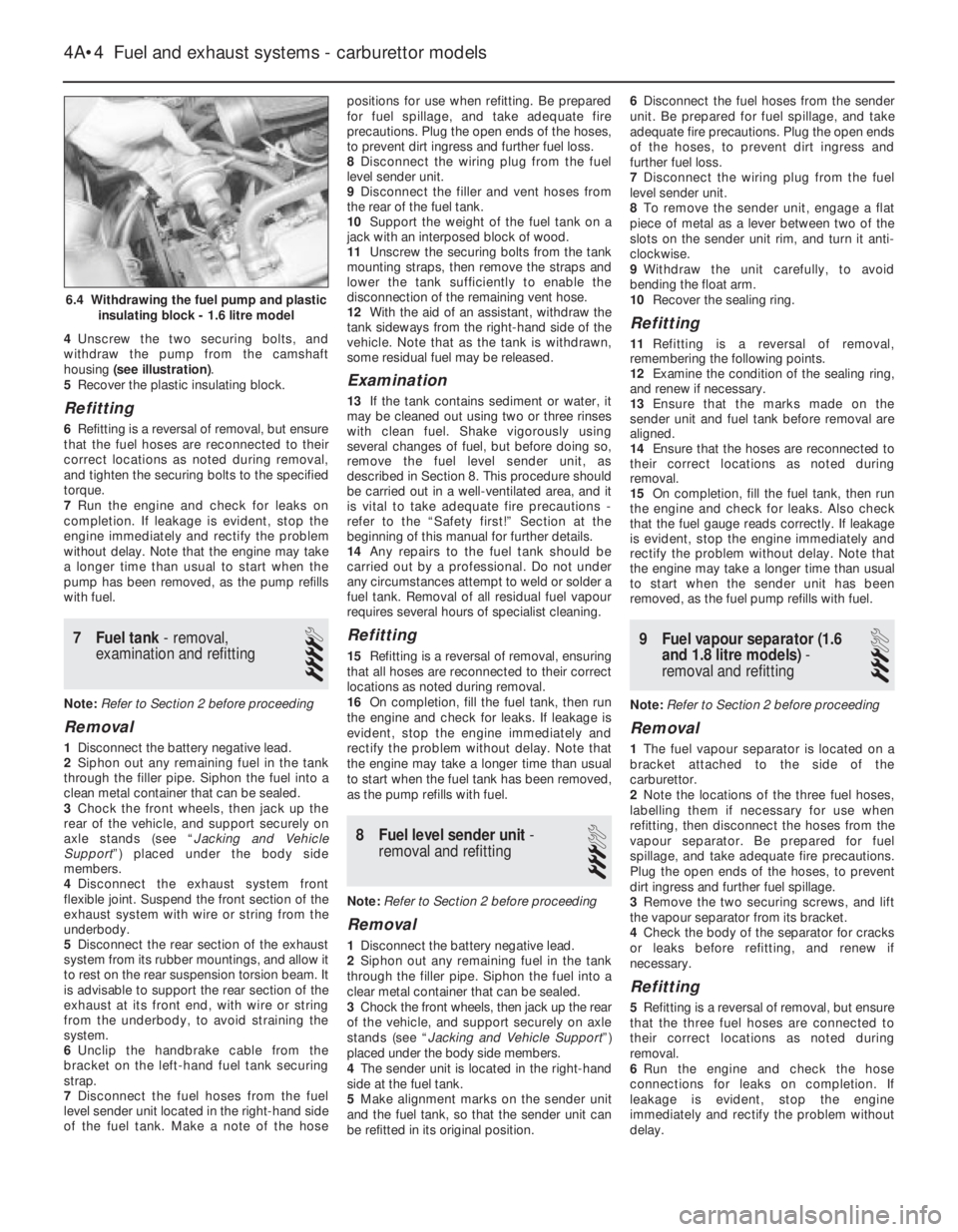
4Unscrew the two securing bolts, and
withdraw the pump from the camshaft
housing (see illustration).
5Recover the plastic insulating block.
Refitting
6Refitting is a reversal of removal, but ensure
that the fuel hoses are reconnected to their
correct locations as noted during removal,
and tighten the securing bolts to the specified
torque.
7Run the engine and check for leaks on
completion. If leakage is evident, stop the
engine immediately and rectify the problem
without delay. Note that the engine may take
a longer time than usual to start when the
pump has been removed, as the pump refills
with fuel.
7Fuel tank - removal,
examination and refitting
4
Note: Refer to Section 2 before proceeding
Removal
1Disconnect the battery negative lead.
2Siphon out any remaining fuel in the tank
through the filler pipe. Siphon the fuel into a
clean metal container that can be sealed.
3Chock the front wheels, then jack up the
rear of the vehicle, and support securely on
axle stands (see “Jacking and Vehicle
Support”) placed under the body side
members.
4Disconnect the exhaust system front
flexible joint. Suspend the front section of the
exhaust system with wire or string from the
underbody.
5Disconnect the rear section of the exhaust
system from its rubber mountings, and allow it
to rest on the rear suspension torsion beam. It
is advisable to support the rear section of the
exhaust at its front end, with wire or string
from the underbody, to avoid straining the
system.
6Unclip the handbrake cable from the
bracket on the left-hand fuel tank securing
strap.
7Disconnect the fuel hoses from the fuel
level sender unit located in the right-hand side
of the fuel tank. Make a note of the hosepositions for use when refitting. Be prepared
for fuel spillage, and take adequate fire
precautions. Plug the open ends of the hoses,
to prevent dirt ingress and further fuel loss.
8Disconnect the wiring plug from the fuel
level sender unit.
9Disconnect the filler and vent hoses from
the rear of the fuel tank.
10Support the weight of the fuel tank on a
jack with an interposed block of wood.
11Unscrew the securing bolts from the tank
mounting straps, then remove the straps and
lower the tank sufficiently to enable the
disconnection of the remaining vent hose.
12With the aid of an assistant, withdraw the
tank sideways from the right-hand side of the
vehicle. Note that as the tank is withdrawn,
some residual fuel may be released.
Examination
13If the tank contains sediment or water, it
may be cleaned out using two or three rinses
with clean fuel. Shake vigorously using
several changes of fuel, but before doing so,
remove the fuel level sender unit, as
described in Section 8. This procedure should
be carried out in a well-ventilated area, and it
is vital to take adequate fire precautions -
refer to the “Safety first!” Section at the
beginning of this manual for further details.
14Any repairs to the fuel tank should be
carried out by a professional. Do not under
any circumstances attempt to weld or solder a
fuel tank. Removal of all residual fuel vapour
requires several hours of specialist cleaning.
Refitting
15Refitting is a reversal of removal, ensuring
that all hoses are reconnected to their correct
locations as noted during removal.
16On completion, fill the fuel tank, then run
the engine and check for leaks. If leakage is
evident, stop the engine immediately and
rectify the problem without delay. Note that
the engine may take a longer time than usual
to start when the fuel tank has been removed,
as the pump refills with fuel.
8Fuel level sender unit -
removal and refitting
3
Note: Refer to Section 2 before proceeding
Removal
1Disconnect the battery negative lead.
2Siphon out any remaining fuel in the tank
through the filler pipe. Siphon the fuel into a
clear metal container that can be sealed.
3Chock the front wheels, then jack up the rear
of the vehicle, and support securely on axle
stands (see “Jacking and Vehicle Support”)
placed under the body side members.
4The sender unit is located in the right-hand
side at the fuel tank.
5Make alignment marks on the sender unit
and the fuel tank, so that the sender unit can
be refitted in its original position.6Disconnect the fuel hoses from the sender
unit. Be prepared for fuel spillage, and take
adequate fire precautions. Plug the open ends
of the hoses, to prevent dirt ingress and
further fuel loss.
7Disconnect the wiring plug from the fuel
level sender unit.
8To remove the sender unit, engage a flat
piece of metal as a lever between two of the
slots on the sender unit rim, and turn it anti-
clockwise.
9Withdraw the unit carefully, to avoid
bending the float arm.
10Recover the sealing ring.
Refitting
11Refitting is a reversal of removal,
remembering the following points.
12Examine the condition of the sealing ring,
and renew if necessary.
13Ensure that the marks made on the
sender unit and fuel tank before removal are
aligned.
14Ensure that the hoses are reconnected to
their correct locations as noted during
removal.
15On completion, fill the fuel tank, then run
the engine and check for leaks. Also check
that the fuel gauge reads correctly. If leakage
is evident, stop the engine immediately and
rectify the problem without delay. Note that
the engine may take a longer time than usual
to start when the sender unit has been
removed, as the fuel pump refills with fuel.
9Fuel vapour separator (1.6
and 1.8 litre models) -
removal and refitting
3
Note: Refer to Section 2 before proceeding
Removal
1The fuel vapour separator is located on a
bracket attached to the side of the
carburettor.
2Note the locations of the three fuel hoses,
labelling them if necessary for use when
refitting, then disconnect the hoses from the
vapour separator. Be prepared for fuel
spillage, and take adequate fire precautions.
Plug the open ends of the hoses, to prevent
dirt ingress and further fuel spillage.
3Remove the two securing screws, and lift
the vapour separator from its bracket.
4Check the body of the separator for cracks
or leaks before refitting, and renew if
necessary.
Refitting
5Refitting is a reversal of removal, but ensure
that the three fuel hoses are connected to
their correct locations as noted during
removal.
6Run the engine and check the hose
connections for leaks on completion. If
leakage is evident, stop the engine
immediately and rectify the problem without
delay.
4A•4Fuel and exhaust systems - carburettor models
6.4 Withdrawing the fuel pump and plastic
insulating block - 1.6 litre model
Page 15 of 525
12
Wiper blades
Type . . . . . . . . . . . . . . . . . . . . . . . . . . . . . . . . . . . . . . . . . . . . . . . . . . . . 19 ins. Champion X-4803
Fuses
Rating:
Red . . . . . . . . . . . . . . . . . . . . . . . . . . . . . . . . . . . . . . . . . . . . . . . . . . . 10 A
Blue . . . . . . . . . . . . . . . . . . . . . . . . . . . . . . . . . . . . . . . . . . . . . . . . . . . 15 A
Yellow . . . . . . . . . . . . . . . . . . . . . . . . . . . . . . . . . . . . . . . . . . . . . . . . . 20 A
Green . . . . . . . . . . . . . . . . . . . . . . . . . . . . . . . . . . . . . . . . . . . . . . . . . 30 A
Torque wrench settingsNm lbf ft
Airbag unit to steering wheel . . . . . . . . . . . . . . . . . . . . . . . . . . . . . . . . . 10 7
Airbag control . . . . . . . . . . . . . . . . . . . . . . . . . . . . . . . . . . . . . . . . . . . . . 10 7
Brackets, passenger airbag . . . . . . . . . . . . . . . . . . . . . . . . . . . . . . . . . . 22 16
Passenger airbag to bracket . . . . . . . . . . . . . . . . . . . . . . . . . . . . . . . . . 8 6
Steering to column . . . . . . . . . . . . . . . . . . . . . . . . . . . . . . . . . . . . . . . . . 25 18
Chapter 12
Body electrical systems
Aerial - removal and refitting . . . . . . . . . . . . . . . . . . . . . . . . . . . . . . .47
Aerial mast, electric - removal and refitting . . . . . . . . . . . . . . . . . . . .48
Airbag - general . . . . . . . . . . . . . . . . . . . . . . . . . . . . . . . . . . . . . . . . .55
Airbag contact unit - removal and refitting . . . . . . . . . . . . . . . . . . . . .58
Airbag control unit - removal and refitting . . . . . . . . . . . . . . . . . . . . .61
Airbag unit, drivers side - removal and refitting . . . . . . . . . . . . . . . . .56
Airbag unit, passengers side - removal and refitting . . . . . . . . . . . . .59
Anti-theft alarm - general . . . . . . . . . . . . . . . . . . . . . . . . . . . . . . . . . .53
Anti-theft alarm system components - removal and refitting . . . . . . .54
Bracket, passenger airbag unit - removal and refitting . . . . . . . . . . .60
Brake lamp switch - removal and refitting . . . . . . . . . . . . . . . . . . . . .12
Central door locking components - removal and refitting . . . . . . . . .46
Check control system components - removal and refitting . . . . . . . .21
Cigarette lighter - removal and refitting . . . . . . . . . . . . . . . . . . . . . . .15
Clock - removal and refitting . . . . . . . . . . . . . . . . . . . . . . . . . . . . . . .16
Courtesy lamp switch - removal and refitting . . . . . . . . . . . . . . . . . . .10
Direction indicator/lighting switch - removal and refitting . . . . . . . . . .5
Electric door mirror switch - removal and refitting . . . . . . . . . . . . . . . .8
Electric window components - removal and refitting . . . . . . . . . . . . .44
Electric window controls - programming . . . . . . . . . . . . . . . . . . . . . .45
Electrical fault-finding - general information . . . . . . . . . . . . . . . . . . . . .2
Exterior lamp bulbs - renewal . . . . . . . . . . . . . . . . . . . . . . . . . . . . . . .34
Facia panel switches - removal and refitting . . . . . . . . . . . . . . . . . . . .7
Front indicator lamp unit - removal and refitting . . . . . . . . . . . . . . . .29
Front foglamp - removal, refitting and adjustment . . . . . . . . . . . . . . .31
Fuses and relays - general . . . . . . . . . . . . . . . . . . . . . . . . . . . . . . . . . .3
General information and precautions . . . . . . . . . . . . . . . . . . . . . . . . . .1
Handbrake “on” warning lamp switch - removal and refitting . . . . . .13
Headlamp aim adjustment motor - removal and refitting . . . . . . . . . .26
Headlamp dim-dip system - general, removal and refitting . . . . . . . .28
Headlamp unit - removal and refitting . . . . . . . . . . . . . . . . . . . . . . . .25
Headlamp washer fluid non-return valve - removal and refitting . . . .43Headlamp wiper motor - removal and refitting . . . . . . . . . . . . . . . . . .40
Headlamps - alignment . . . . . . . . . . . . . . . . . . . . . . . . . . . . . . . . . . .27
Heated front seats - general . . . . . . . . . . . . . . . . . . . . . . . . . . . . . . . .17
Horn(s) - removal and refitting . . . . . . . . . . . . . . . . . . . . . . . . . . . . . .22
Ignition switch and lock cylinder - removal and refitting . . . . . . . . . . .4
Instrument panel - removal and refitting . . . . . . . . . . . . . . . . . . . . . .18
Instrument panel components - removal and refitting . . . . . . . . . . . .19
Interior lamp bulbs - renewal . . . . . . . . . . . . . . . . . . . . . . . . . . . . . . .24
Interior lamps - removal and refitting . . . . . . . . . . . . . . . . . . . . . . . . .23
Luggage compartment lamp switch - removal and refitting . . . . . . .11
Number plate lamp - removal and refitting . . . . . . . . . . . . . . . . . . . . .33
Oil pressure warning lamp switch - removal and refitting . . . . . . . . .14
Radio/cassette player - removal and refitting . . . . . . . . . . . . . . . . . . .50
Rear lamp unit - removal and refitting . . . . . . . . . . . . . . . . . . . . . . . .32
Reversing lamp switch . . . . . . . . . . . . . . . . . . . . . . . . .See Chapter 7A
Side repeater lamp - removal and refitting . . . . . . . . . . . . . . . . . . . . .30
Speakers - removal and refitting . . . . . . . . . . . . . . . . . . . . . . . . . . . .49
Speedometer cable - removal and refitting . . . . . . . . . . . . . . . . . . . .52
Steering wheel (with airbag) - removal and refitting . . . . . . . . . . . . . .57
Sunroof motor - removal and refitting . . . . . . . . . . . . . . . . . . . . . . . .51
Sunroof operating switch - removal and refitting . . . . . . . . . . . . . . . . .9
Tailgate wiper motor - removal and refitting . . . . . . . . . . . . . . . . . . . .39
Trip computer components - removal and refitting . . . . . . . . . . . . . .20
Wash/wipe switch - removal and refitting . . . . . . . . . . . . . . . . . . . . . .6
Washer fluid reservoir - removal and refitting . . . . . . . . . . . . . . . . . . .41
Washer nozzles - removal and refitting . . . . . . . . . . . . . . . . . . . . . . .37
Washer pump - removal and refitting . . . . . . . . . . . . . . . . . . . . . . . . .42
Windscreen wiper motor and linkage - removal and refitting . . . . . . .38
Wiper arms - removal and refitting . . . . . . . . . . . . . . . . . . . . . . . . . . .36
Wiper blades - renewal . . . . . . . . . . . . . . . . . . . . . . . . . . . . . . . . . . . .35
Wiring diagrams - general . . . . . . . . . . . . . . . . . . . . . . . . . . . . . . . . .62
12•1
Specifications Contents
Easy,suitable for
novice with little
experienceFairly easy,suitable
for beginner with
some experienceFairly difficult,
suitable for competent
DIY mechanic
Difficult,suitable for
experienced DIY
mechanicVery difficult,
suitable for expert DIY
or professional
Degrees of difficulty
54321
Page 19 of 525
8Electric door mirror switch -
removal and refitting
2
Removal
1Disconnect the battery negative lead.
2Prise the plastic surround from the door
interior handle.
3Free the trim panel from the top edge of the
door by releasing the securing clips. This can
be done using a screwdriver, but it is
preferable to use a forked tool, to minimise
the possibility of damage to the trim panel and
the clips.
4Note the position of the mirror switch wiring
connector in the bracket at the top of the
door, then separate the two halves of the
connector.
5Prise the switch from the door trim panel,
and feed the wiring through the panel.
Refitting
6Refitting is a reversal of removal, but ensure
that the wiring is correctly routed, so as not to
foul the door interior handle mechanism.
9Sunroof operating switch -
removal and refitting
2
Removal
1Disconnect the battery negative lead.
2Prise the courtesy lamp from the roof trim
panel, and disconnect the wiring.
3Remove the two trim panel securing
screws, and withdraw the trim panel from the
roof, disconnecting the wiring from the
sunroof operating switch.
4Release the securing clips, then pull the
switch from the rear face of the trim panel.
Refitting
5Refitting is a reversal of removal.
10Courtesy lamp switch -
removal and refitting
2
Removal
1Disconnect the battery negative lead.
2Open the door and remove the switch
securing screw.
3Withdraw the switch from the door pillar,
and pull the wiring out sufficiently to prevent it
from springing back into the pillar.4Disconnect the wiring and remove the
switch.
Refitting
5Refitting is a reversal of removal.
11Luggage compartment lamp
switch - removal and refitting
2
Removal
1Disconnect the battery negative lead.
2Open the boot lid or tailgate, as applicable,
and remove the switch securing screw.
3Withdraw the switch from the body panel,
and pull the wiring out sufficiently to prevent it
from springing back into the body.
4Disconnect the wiring and remove the
switch.
Refitting
5Refitting is a reversal of removal.
12Brake lamp switch - removal
and refitting
2
Removal
1Disconnect the battery negative lead.
2Remove the lower trim panel from the
driver’s footwell.
3Disconnect the wiring plug from the brake
lamp switch, then twist the switch
anti-clockwise and remove it from its bracket.
Refitting
4Refitting is a reversal of removal.
13Handbrake “on” warning
lamp switch - removal and
refitting
3
For access to the switch, the handbrake
lever must be removed. Removal and refitting
of the switch is described as part of the
handbrake lever removal and refitting
procedure, in Chapter 9.
14Oil pressure warning lamp
switch - removal and refitting
3
Removal
1Disconnect the battery negative lead.
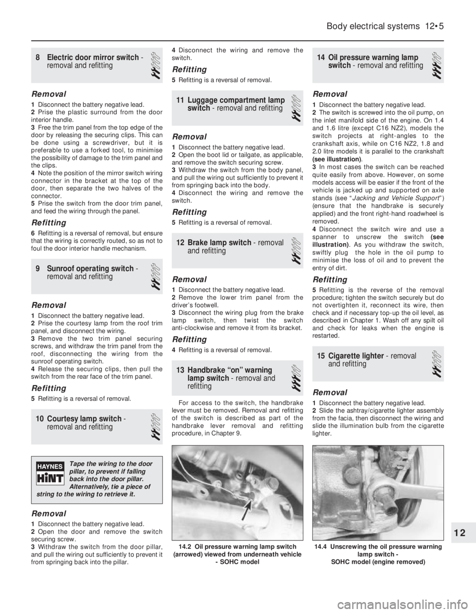
2The switch is screwed into the oil pump, on
the inlet manifold side of the engine. On 1.4
and 1.6 litre (except C16 NZ2), models the
switch projects at right-angles to the
crankshaft axis, while on C16 NZ2, 1.8 and
2.0 litre models it is parallel to the crankshaft
(see illustration).
3In most cases the switch can be reached
quite easily from above. However, on some
models access will be easier if the front of the
vehicle is jacked up and supported on axle
stands (see “Jacking and Vehicle Support”)
(ensure that the handbrake is securely
applied) and the front right-hand roadwheel is
removed.
4Disconnect the switch wire and use a
spanner to unscrew the switch (see
illustration). As you withdraw the switch,
swiftly plug the hole in the oil pump to
minimise the loss of oil and to prevent the
entry of dirt.
Refitting
5Refitting is the reverse of the removal
procedure; tighten the switch securely but do
not overtighten it, reconnect its wire, then
check and if necessary top-up the oil level, as
described in Chapter 1. Wash off any spilt oil
and check for leaks when the engine is
restarted.
15Cigarette lighter - removal
and refitting
2
Removal
1Disconnect the battery negative lead.
2Slide the ashtray/cigarette lighter assembly
from the facia, then disconnect the wiring and
slide the illumination bulb from the cigarette
lighter.
Body electrical systems 12•5
14.4 Unscrewing the oil pressure warning
lamp switch -
SOHC model (engine removed)14.2 Oil pressure warning lamp switch
(arrowed) viewed from underneath vehicle
- SOHC model
12
Tape the wiring to the door
pillar, to prevent if falling
back into the door pillar.
Alternatively, tie a piece of
string to the wiring to retrieve it.
Page 22 of 525
Brake fluid level sensor
14The procedure is as described for the
coolant level sensor in paragraphs 7 to 10
inclusive.
Engine oil level sensor
Removal
15Apply the handbrake, jack up the front of
the vehicle, and support securely on axle
stands (see “Jacking and Vehicle Support”)
positioned under the body side members.
16On DOHC models, remove the engine
undershield, as described in Chapter 11.
17Disconnect the sensor wiring plug.
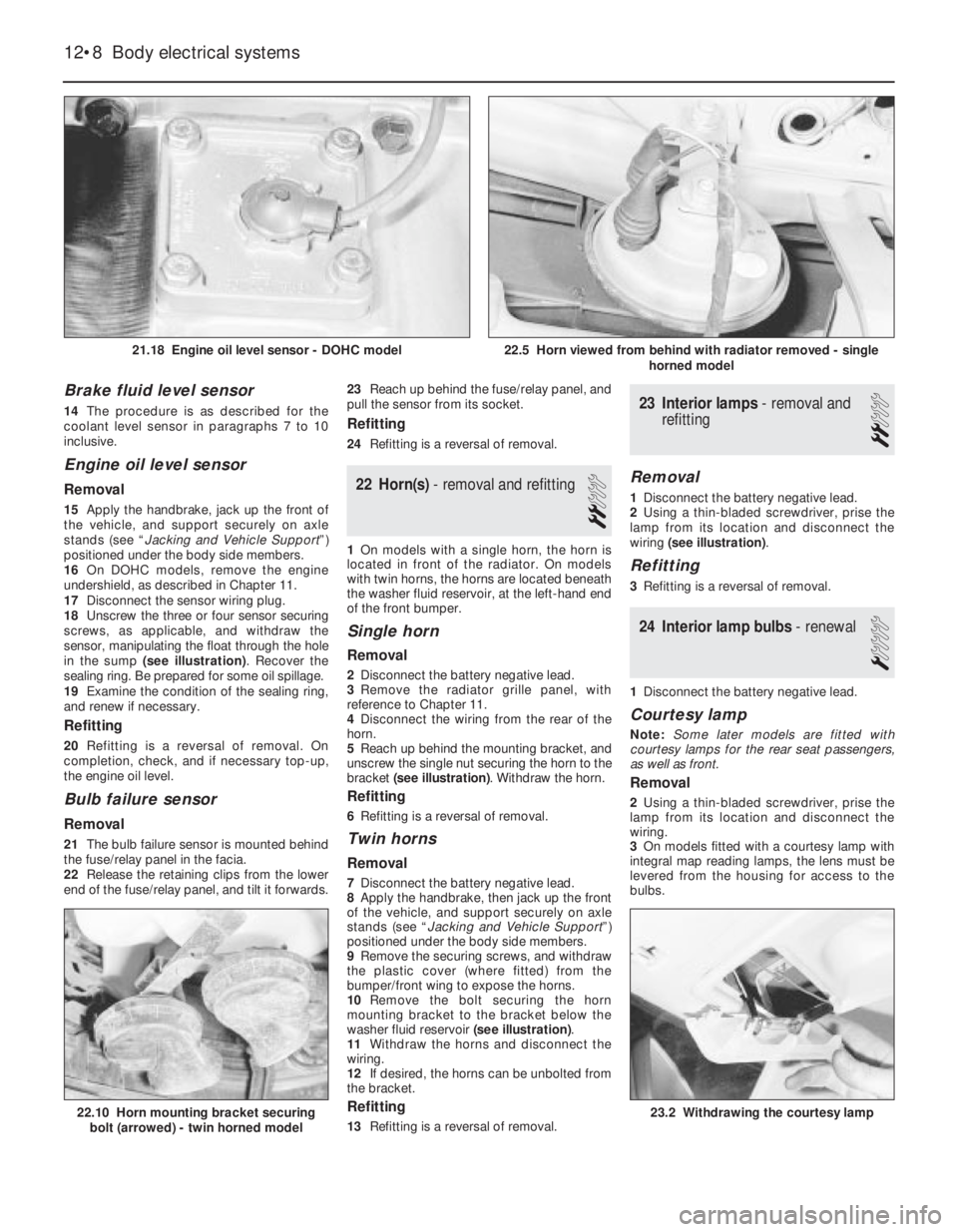
18Unscrew the three or four sensor securing
screws, as applicable, and withdraw the
sensor, manipulating the float through the hole
in the sump (see illustration). Recover the
sealing ring. Be prepared for some oil spillage.
19Examine the condition of the sealing ring,
and renew if necessary.
Refitting
20Refitting is a reversal of removal. On
completion, check, and if necessary top-up,
the engine oil level.
Bulb failure sensor
Removal
21The bulb failure sensor is mounted behind
the fuse/relay panel in the facia.
22Release the retaining clips from the lower
end of the fuse/relay panel, and tilt it forwards.23Reach up behind the fuse/relay panel, and
pull the sensor from its socket.
Refitting
24Refitting is a reversal of removal.
22Horn(s) - removal and refitting
2
1On models with a single horn, the horn is
located in front of the radiator. On models
with twin horns, the horns are located beneath
the washer fluid reservoir, at the left-hand end
of the front bumper.
Single horn
Removal
2Disconnect the battery negative lead.
3Remove the radiator grille panel, with
reference to Chapter 11.
4Disconnect the wiring from the rear of the
horn.
5Reach up behind the mounting bracket, and
unscrew the single nut securing the horn to the
bracket (see illustration). Withdraw the horn.
Refitting
6Refitting is a reversal of removal.
Twin horns
Removal
7Disconnect the battery negative lead.
8Apply the handbrake, then jack up the front
of the vehicle, and support securely on axle
stands (see “Jacking and Vehicle Support”)
positioned under the body side members.
9Remove the securing screws, and withdraw
the plastic cover (where fitted) from the
bumper/front wing to expose the horns.
10Remove the bolt securing the horn
mounting bracket to the bracket below the
washer fluid reservoir (see illustration).
11Withdraw the horns and disconnect the
wiring.
12If desired, the horns can be unbolted from
the bracket.
Refitting
13Refitting is a reversal of removal.
23Interior lamps - removal and
refitting
2
Removal
1Disconnect the battery negative lead.
2Using a thin-bladed screwdriver, prise the
lamp from its location and disconnect the
wiring (see illustration).
Refitting
3Refitting is a reversal of removal.
24Interior lamp bulbs - renewal
1
1Disconnect the battery negative lead.
Courtesy lamp
Note: Some later models are fitted with
courtesy lamps for the rear seat passengers,
as well as front.
Removal
2Using a thin-bladed screwdriver, prise the
lamp from its location and disconnect the
wiring.
3On models fitted with a courtesy lamp with
integral map reading lamps, the lens must be
levered from the housing for access to the
bulbs.
12•8Body electrical systems
21.18 Engine oil level sensor - DOHC model
22.10 Horn mounting bracket securing
bolt (arrowed) - twin horned model23.2 Withdrawing the courtesy lamp
22.5 Horn viewed from behind with radiator removed - single
horned model
Page 25 of 525
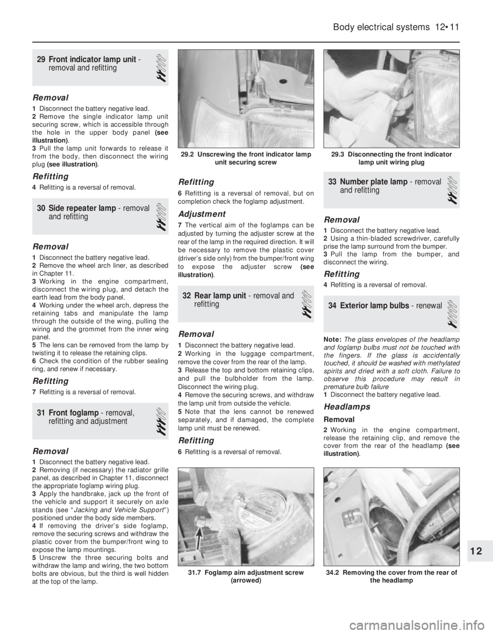
29Front indicator lamp unit -
removal and refitting
2
Removal
1Disconnect the battery negative lead.
2Remove the single indicator lamp unit
securing screw, which is accessible through
the hole in the upper body panel (see
illustration).
3Pull the lamp unit forwards to release it
from the body, then disconnect the wiring
plug (see illustration).
Refitting
4Refitting is a reversal of removal.
30Side repeater lamp -removal
and refitting
2
Removal
1Disconnect the battery negative lead.
2Remove the wheel arch liner, as described
in Chapter 11.
3Working in the engine compartment,
disconnect the wiring plug, and detach the
earth lead from the body panel.
4Working under the wheel arch, depress the
retaining tabs and manipulate the lamp
through the outside of the wing, pulling the
wiring and the grommet from the inner wing
panel.
5The lens can be removed from the lamp by
twisting it to release the retaining clips.
6Check the condition of the rubber sealing
ring, and renew if necessary.
Refitting
7Refitting is a reversal of removal.
31Front foglamp - removal,
refitting and adjustment
3
Removal
1Disconnect the battery negative lead.
2Removing (if necessary) the radiator grille
panel, as described in Chapter 11, disconnect
the appropriate foglamp wiring plug.
3Apply the handbrake, jack up the front of
the vehicle and support it securely on axle
stands (see “Jacking and Vehicle Support”)
positioned under the body side members.
4If removing the driver’s side foglamp,
remove the securing screws and withdraw the
plastic cover from the bumper/front wing to
expose the lamp mountings.
5Unscrew the three securing bolts and
withdraw the lamp and wiring, the two bottom
bolts are obvious, but the third is well hidden
at the top of the lamp.
Refitting
6Refitting is a reversal of removal, but on
completion check the foglamp adjustment.
Adjustment
7The vertical aim of the foglamps can be
adjusted by turning the adjuster screw at the
rear of the lamp in the required direction. It will
be necessary to remove the plastic cover
(driver’s side only) from the bumper/front wing
to expose the adjuster screw (see
illustration).
32Rear lamp unit - removal and
refitting
2
Removal
1Disconnect the battery negative lead.
2Working in the luggage compartment,
remove the cover from the rear of the lamp.
3Release the top and bottom retaining clips,
and pull the bulbholder from the lamp.
Disconnect the wiring plug.
4Remove the securing screws, and withdraw
the lamp unit from outside the vehicle.
5Note that the lens cannot be renewed
separately, and if damaged, the complete
lamp unit must be renewed.
Refitting
6Refitting is a reversal of removal.
33Number plate lamp -removal
and refitting
2
Removal
1Disconnect the battery negative lead.
2Using a thin-bladed screwdriver, carefully
prise the lamp surround from the bumper.
3Pull the lamp from the bumper, and
disconnect the wiring.
Refitting
4Refitting is a reversal of removal.
34Exterior lamp bulbs - renewal
1
Note: The glass envelopes of the headlamp
and foglamp bulbs must not be touched with
the fingers. If the glass is accidentally
touched, it should be washed with methylated
spirits and dried with a soft cloth. Failure to
observe this procedure may result in
premature bulb failure
1Disconnect the battery negative lead.
Headlamps
Removal
2Working in the engine compartment,
release the retaining clip, and remove the
cover from the rear of the headlamp (see
illustration).
Body electrical systems 12•11
31.7 Foglamp aim adjustment screw
(arrowed)34.2 Removing the cover from the rear of
the headlamp
29.3 Disconnecting the front indicator
lamp unit wiring plug29.2 Unscrewing the front indicator lamp
unit securing screw
12
Page 26 of 525
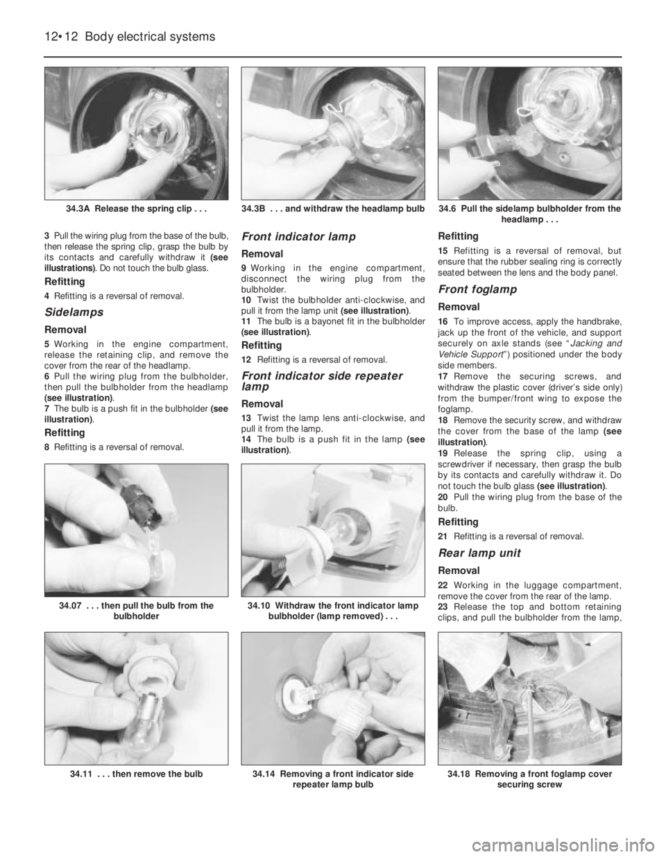
3Pull the wiring plug from the base of the bulb,
then release the spring clip, grasp the bulb by
its contacts and carefully withdraw it (see
illustrations). Do not touch the bulb glass.
Refitting
4Refitting is a reversal of removal.
Sidelamps
Removal
5Working in the engine compartment,
release the retaining clip, and remove the
cover from the rear of the headlamp.
6Pull the wiring plug from the bulbholder,
then pull the bulbholder from the headlamp
(see illustration).
7The bulb is a push fit in the bulbholder (see
illustration).
Refitting
8Refitting is a reversal of removal.
Front indicator lamp
Removal
9Working in the engine compartment,
disconnect the wiring plug from the
bulbholder.
10Twist the bulbholder anti-clockwise, and
pull it from the lamp unit (see illustration).
11The bulb is a bayonet fit in the bulbholder
(see illustration).
Refitting
12Refitting is a reversal of removal.
Front indicator side repeater
lamp
Removal
13Twist the lamp lens anti-clockwise, and
pull it from the lamp.
14The bulb is a push fit in the lamp (see
illustration).
Refitting
15Refitting is a reversal of removal, but
ensure that the rubber sealing ring is correctly
seated between the lens and the body panel.
Front foglamp
Removal
16To improve access, apply the handbrake,
jack up the front of the vehicle, and support
securely on axle stands (see “Jacking and
Vehicle Support”) positioned under the body
side members.
17Remove the securing screws, and
withdraw the plastic cover (driver’s side only)
from the bumper/front wing to expose the
foglamp.
18Remove the security screw, and withdraw
the cover from the base of the lamp (see
illustration).
19Release the spring clip, using a
screwdriver if necessary, then grasp the bulb
by its contacts and carefully withdraw it. Do
not touch the bulb glass (see illustration).
20Pull the wiring plug from the base of the
bulb.
Refitting
21Refitting is a reversal of removal.
Rear lamp unit
Removal
22Working in the luggage compartment,
remove the cover from the rear of the lamp.
23Release the top and bottom retaining
clips, and pull the bulbholder from the lamp,
12•12Body electrical systems
34.3A Release the spring clip . . .34.6 Pull the sidelamp bulbholder from the
headlamp . . .
34.18 Removing a front foglamp cover
securing screw
34.10 Withdraw the front indicator lamp
bulbholder (lamp removed) . . .34.07 . . . then pull the bulb from the
bulbholder
34.14 Removing a front indicator side
repeater lamp bulb34.11 . . . then remove the bulb
34.3B . . . and withdraw the headlamp bulb
Page 29 of 525
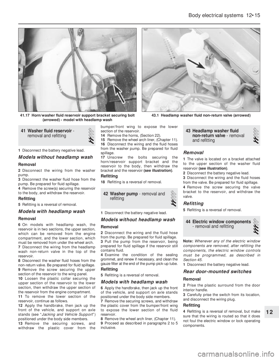
41Washer fluid reservoir -
removal and refitting
2
1Disconnect the battery negative lead.
Models without headlamp wash
Removal
2Disconnect the wiring from the washer
pump.
3Disconnect the washer fluid hose from the
pump. Be prepared for fluid spillage.
4Remove the screw(s) securing the reservoir
to the body, and withdraw the reservoir.
Refitting
5Refitting is a reversal of removal.
Models with headlamp wash
Removal
6On models with headlamp wash, the
reservoir is in two sections, the upper section,
which can be removed from the engine
compartment, and the lower section, which
must be removed from under the wheel arch.
7Disconnect the wiring from the headlamp
wash non-return valve in the top of the
reservoir.
8Disconnect the washer fluid hoses from the
non-return valve. Be prepared for fluid spillage.
9Remove the screw securing the upper
section of the reservoir to the wing panel.
10Loosen the plastic collar securing the
upper section of the reservoir to the lower
section, then withdraw the upper section of
the reservoir from the engine compartment.
11To remove the lower section of the
reservoir, continue as follows.
12Apply the handbrake, then jack up the
front of the vehicle, and support on axle
stands (see “Jacking and Vehicle Support”)
positioned under the body side members.
13Remove the securing screws, and
withdraw the plastic cover from thebumper/front wing to expose the lower
section of the reservoir.
14Remove the horns, (Section 22).
15Remove the wheel arch liner, (Chapter 11).
16Disconnect the wiring and the fluid hoses
from the washer pump. Be prepared for fluid
spillage.
17Unscrew the bolts securing the
horn/reservoir support bracket and the
reservoir to the body, then withdraw the
bracket and the reservoir (see illustration).
Refitting
18Refitting is a reversal of removal.
42Washer pump -removal and
refitting
2
1Disconnect the battery negative lead.
Models without headlamp wash
Removal
2Disconnect the wiring and the fluid hose
from the pump. Be prepared for fluid spillage.
3Pull the pump from the reservoir, being
prepared for fluid spillage if the reservoir still
contains fluid.
4Examine the condition of the sealing
grommet, and renew if necessary, and clean the
gauze filter at the end of the pump pick-up tube.
Refitting
5Refitting is a reversal of removal.
Models with headlamp wash
6Apply the handbrake, then jack up the front
of the vehicle, and support on axle stands
positioned under the body side members.
7Remove the securing screws, and withdraw
the plastic cover from the bumper/front wing
to expose the lower section of the fluid
reservoir.
8Remove the wheel arch liner, (Chapter 11).
9Proceed as described in paragraphs 2 to 5
inclusive.
43Headlamp washer fluid
non-return valve -removal
and refitting
2
Removal
1The valve is located on a bracket attached
to the upper section of the washer fluid
reservoir (see illustration).
2Disconnect the battery negative lead.
3Disconnect the wiring and the fluid hoses
from the valve. Be prepared for fluid spillage.
4Remove the screw securing the valve
bracket to the reservoir, and withdraw the
valve.
Refitting
5Refitting is a reversal of removal.
44Electric window components
- removal and refitting
3
Note: Whenever any of the electric window
components are removed, after refitting the
components, the electric window controls
must be programmed, as described in
Section 45.
1Disconnect the battery negative lead.
Rear door-mounted switches
Removal
2Prise the plastic surround from the door
interior handle.
3Carefully prise the switch from its location,
and disconnect the wiring plug.
Refitting
4Refitting is a reversal of removal, but make
sure that the wiring is routed so that it does
not foul the electric window or lock operating
components.
Body electrical systems 12•15
43.1 Headlamp washer fluid non-return valve (arrowed)41.17 Horn/washer fluid reservoir support bracket securing bolt
(arrowed) - model with headlamp wash
12
Page 37 of 525
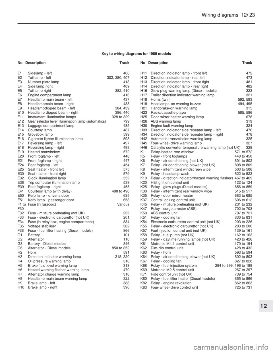
Wiring diagrams 12•23
12
Key to wiring diagrams for 1989 models
E1Sidelamp - left406
E2Tail lamp -left302, 380, 407
E3Number plate lamp413
E4Side lamp right409
E5Tail lamp right382, 410
E6Engine compartment lamp416
E7Headlamp main beam - left437
E8Headlampmain beam - right438
E9Headlampdipped beam - left384, 439
E10Headlamp dipped beam - right386, 440
E11Instrument illumination lamps328 to 329
E12Gear selector lever illumination lamp (automatics)799
E13Luggage compartment lamp485
E14Courtesy lamp487
E15Glovebox lamp599
E16Cigarette lighter illumination lamp598
E17Reversing lamp - left497
E18Reversing lamp - right498
E19Heated rearwindow572
E20Front foglamp -left448
E21Front foglamp - right447
E24Rear foglamp - left454
E25Seat heater -front left575
E30Seat heater - front right579
E32Clock illumination lamp552
E38Trip computer illumination lamp539
E39Rear foglamp - right455
E41Courtesy lamp (with delay)488 to 490
E50Kerb lamp - driver’s door635
E51Kerb lamp - passenger door653
F1 toFuse (in fusebox)Various
F30
F32Fuse - mixture preheating (not UK)232
F33Fuse - electronic carburettor (not UK)201
F34Fuse (in relay box, engine compartment)834
F35Voltage stabiliser302
F36Fuse - fuel filter heating (Diesel models)866
G1Battery101
G2Alternator110
G3Battery - Diesel models846
G6Alternator - Diesel models850 to 852
H2Horn591
H3Direction indicator warning lamp318, 320
H4Oil pressure warning lamp310
H5Brake fluid level warning lamp313
H6Hazard warning flasher warning lamp470
H7Alternator charge warning lamp310
H8Headlamp main beam warning lamp322
H9Brake lamp - left388
H10Brake lamp - right390H11Direction indicator lamp - front left472
H12Direction indicatorlamp - rear left473
H13Direction indicator lamp - front right481
H14Direction indicator lamp - rear right482
H16Glow plug warning lamp (Diesel models)323
H17Trailer direction indicator warning lamp321
H18Horns (twin)592, 593
H19Headlamps-on warning buzzer494, 495
H21Handbrake-on warning lamp315
H23Radio/cassette player585, 586
H25Door mirror heater warning lamp678
H26ABS warning lamp319
H30Engine fault warning lamp324
H33Direction indicator side repeater lamp - left476
H34Direction indicator side repeater lamp - right478
H42Automatic transmission warning lamp325
H45Four-wheel-drive warning lamp327
H46Catalytic converter temperature warning lamp (not UK)329
K1Relay-heated rear window571 to 572
K5Relay - front foglamps448 to 450
K6Relay - air conditioning (not UK)801 to 802
K7Relay - air conditioning blower (not UK)808 to 809
K8Relay - intermittent windscreen wipe503 to 506
K9Relay - headlamp wash522 to 523
K10Relay - direction indicator/hazard warning flashers467 to 469
K20HEI ignition control unit122 to 124
K25Relay - glow plugs (Diesel models)856 to 859
K30Relay - intermittent rear window wipe515 to 517
K35Relay - door mirror heater683 to 685
K37Central locking control unit606 to 612
K45Relay - mixture preheating (not UK)231 to 232
K47Relay - surge arrester (ABS)702 to 703
K50ABS control unit707 to 721
K51Relay - cooling fan830 to 831
K54Electronic carburettor control unit (not UK)203 to 226
K55Relay - electronic carburettor (not UK)203 to 206
K57Fuel injection control unit (not UK)139 to 161
K58Relay -fuel pump (not UK)162 to 163
K59Relay - daytime running lamps (not UK)420 to 426
K61Motronic M4.1 control unit170 to 194
K62Dim-dip control unit428 to 432
K63Relay - horn593 to 594
K64Relay - air conditioning blower (not UK)802 to 803
K67Relay -cooling fan827 to 828
K68Relay -fuel injection system294 to 299, 196 to 199
K69Motronic M2.5 control unit267 to 297
K71Ride control unit (not UK)739 to 754
K80Relay -fuel filter heater (Diesel models)865 to 866
K82Relay - engine revolution862 to 863
K83Four-wheel-drive control unit725 to 731 NoDescriptionTrackNoDescriptionTrack
Page 38 of 525
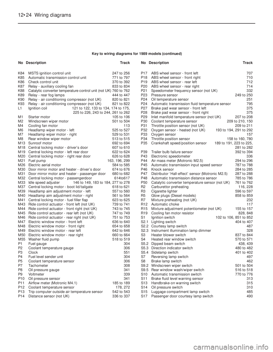
12•24Wiring diagrams
K84MSTS ignition control unit247 to 256
K85Automatic transmission control unit771 to 797
K86Check control unit370 to 392
K87Relay - auxiliary cooling fan833 to 834
K88Catalytic converter temperature control unit (not UK)760 to 762
K89Relay - rear fog lamps444 to 447
K90Relay - air conditioning compressor (not UK)820 to 821
K93Relay - air conditioning compressor (not UK)821 to 822
L1Ignition coil121 to 122, 133 to 134, 174 to 175,
225 to 226, 243 to 244, 261 to 262
M1Starter motor105 to 106
M2Windscreen wiper motor501 to 504
M4Cooling fan motor113
M6Headlamp wiper motor -left525 to 527
M7Headlamp wiper motor - right529 to 531
M8Rear window wiper motor513 to 515
M13Sunroof motor692 to 694
M18Central locking motor - driver’s door607 to 610
M19Central locking motor - left rear door622 to 624
M20Central locking motor - right rear door626 to 628
M21Fuel pump163, 196, 299
M26Electric aerial motor584 to 585
M30Door mirror motor and heater - driver’s door674 to 676
M31Door mirror motor and heater - passenger door680 to 682
M32Central locking motor - passengerdoor614to617
M33Idle speed adjuster146 to 149, 183 to 184, 277 to 278
M37Central locking motor - boot lid/tailgate618 to 621
M39Headlamp aim adjustment motor -left557 to 560
M40Headlamp aim adjustment motor - right561 to 564
M41Central locking motor - fuel filler flap623 to 625
M43Ride control actuator - front left (not UK)739 to 741
M44Ride control actuator - front right (not UK)743 to 745
M45Ride control actuator -rear left (not UK)747 to 749
M46Ride control actuator - rear right (not UK)751 to 753
M47Electric window motor - front left636 to 640
M48Electric window motor - front right654 to 658
M49Electric window motor - rear left642 to 646
M50Electric window motor - rear right660 to 664
M55Washer fluid pump518 to 519
P1Fuel gauge304
P2Coolant temperature gauge306
P3Clock551
P4Fuel level sender unit304
P5Coolant temperature sensor306
P7Tachometer308
P8Oil pressure gauge341
P9Voltmeter339
P10Oil pressure sensor341
P11Airflow meter (Motronic M4.1)185 to 189
P12Coolant temperature sensor178, 272
P13Trip computer outside air temperature sensor542 to 543
P14Distance sensor (not UK)336 to 337P17ABS wheel sensor - front left707
P18ABS wheel sensor -front right710
P19ABS wheel sensor -rear left712
P20ABS wheel sensor - rear right714
P21Speedometer frequency sensor (not UK)332
P23Pressure sensor 249 to 250
P24Oil temperature sensor251
P24Automatic transmission fluid temperature sensor795
P27Brake pad wear sensor - front left375
P28Brake pad wear sensor - front right375
P29Inlet manifold temperature sensor (not UK)207 to 208
P30Coolant temperature sensor209 to 210, 150
P31Throttle position sensor (not UK)209 to 211
P32Oxygen sensor - heated (not UK)193 to 194, 291 to 292
P33Oxygen sensor157
P34Throttle position sensor158 to 160, 780
P35Crankshaft speed/position sensor189 to 191, 223 to 225,
281 to 282
P39Trailer bulb failure sensor392 to 394
P43Electronic speedometer336
P44Air mass meter (Motronic M2.5)294 to 296
P45Automatic transmission input speed sensor787 to 788
P46Knock sensor284 to 285
P47Distributor ‘Hall-effect’ sensor (Motronic M2.5)287 to 288
P48Automatic transmission distance sensor785 to 786
P50Catalytic converter temperature sensor (not UK)761 to 762
R2Carburettor preheating116, 228
R3Cigarette lighter596 to 597
R5Glow plugs (Diesel models)858 to 859
R7Mixture preheating (not UK)232
R12Automatic choke117
R15Mixture adjustment potentiometer (not UK)155 to 157
R19Cooling fan motor resistor828, 848
S1Ignition switch102 to 106, 851 to 852
S2.1Lighting switch404 to 407
S2.2Courtesy lamp switch487
S2.3Instrument illumination lamp dimmer328
S3Heater blower switch837 to 844
S4Heated rear window switch570 to 571
S5.2Dipped beam switch438, 439
S5.3Direction indicator switch480 to 482
S5.4Sidelamp switch401 to 402
S7Reversing lamp switch497
S8Brake lamp switch462
S9.2Windscreen wiper switch501 to 504
S9.5Rear window wash/wiper switch516 to 518
S10Automatic transmission switch770 to 776
S11Brake fluid level warning sensor313
S13Handbrake-on warning switch315
S14Oil pressure switch310
S15Luggage compartment lamp switch485
S17Passenger door courtesy lamp switch490 Key to wiring diagrams for 1989 models (continued)
NoDescriptionTrackNoDescriptionTrack
Page 52 of 525
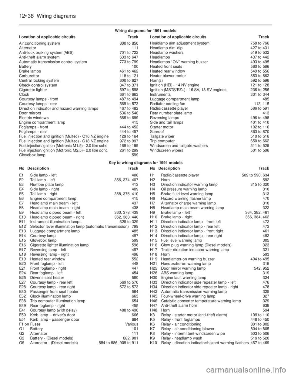
12•38Wiring diagrams
Key to wiring diagrams for 1991 models
NoDescriptionTrackNoDescriptionTrack Wiring diagrams for 1991 models
Location of applicable circuitsTrackLocation of applicable circuitsTrack
Air conditioning system800 to 850
Alternator111
Anti-lock braking system (ABS)701 to 722
Anti-theft alarm system633 to 647
Automatic transmission control system773 to 799
Battery100
Brake lamps461 to 462
Carburettor118 to 121
Central locking system600 to 627
Check control system347 to 371
Cigarette lighter597 to 598
Clock661 to 663
Courtesy lamps - front487 to 494
Courtesy lamps - rear569 to 573
Direction indicator and hazard warning lamps467 to 482
Door mirrors536 to 548
Electric windows665 to 699
Engine compartment lamp415
Foglamps - front444 to 452
Foglamps - rear444 to 457
Fuel injection and ignition (Multec) - C16NZ engine129 to 164
Fuel injection and ignition (Multec) - C18NZ engine972 to 997
Fuel injection/ignition (Motronic M1.5) - 2.0litre sohc 168 to 199
Fuel injection/ignition (Motronic M2.5) - 2.0litre dohc 261 to 299
Glovebox lamp599Headlamp aim adjustment system758 to 766
Headlamp dim-dip427 to 431
Headlamp washers519 to 532
Headlamps437 to 442
Headlamps “ON” warning buzzer493 to 495
Heated front seats560 to 566
Heated rear window549 to 556
Heater blower motor853 to 862
Horn(s)592 to 596
Ignition (HEI) - 14NV engine121 to 128
Ignition (MSTS/EZ+) - 16SV, 18 SV engines236 to 256
Instruments301 to 344
Luggage compartment lamp485
Radiator cooling fan113, 115
Radio/cassette player586 to 591
Rear number plate lamp413
Reversing lamps496 to 498
Side and tail lamps401 to 410
Starter motor102 to 110
Sunroof863 to 870
Tailgate wiper510 to 516
Trip computer650 to 662
Windscreen and tailgate washers511 to 529
Windscreen wipers501 to 506
E1Side lamp - left406
E2Tail lamp - left356, 374, 407
E3Number plate lamp413
E4Side lamp - right409
E5Tail lamp - right358, 376, 410
E6Engine compartment lamp415
E7Headlamp main beam - left437
E8Headlamp main beam - right438
E9Headlamp dipped beam - left360, 378, 439
E10Headlamp dipped beam - right362, 380, 440
E11Instrument illumination lamps328 to 329
E12Selector lever illumination lamp (automatic transmission)799
E13Luggage compartment lamp485
E14Courtesy lamp487
E15Glovebox lamp599
E16Cigarette lighter illumination lamp596
E17Reversing lamp - left497
E18Reversing lamp - right498
E19Heated rear window552
E20Front foglamp - left448
E21Front foglamp - right447
E24Rear foglamp - left454
E25Driver’s seat heater580
E27Courtesy lamp - rear left569 to 570
E28Courtesy lamp - rear right572 to 573
E30Passenger front seat heater564
E32Clock illumination lamp663
E38Trip computer illumination lamp654
E39Rear foglamp - right455
E41Courtesy lamp (with delay)488 to 490
E50Kerb lamp - driver’s door666
E51Kerb lamp - passenger door684
F1 onFusesVarious
G1Battery101
G2Alternator111
G3Battery - (Diesel models)882, 901
G6Alternator - (Diesel models)884 to 886, 909 to 911H1Radio/cassette player589 to 590, 634
H2Horn592
H3Direction indicator warning lamp315 to 320
H4Oil pressure warning lamp310
H5Brake fluid level warning lamp313
H6Hazard warning flasher lamp470
H7Alternator charge warning lamp310
H8Headlamp main beam warning lamp322
H9Brake lamp - left364, 382, 461
H10Brake lamp - right366, 384, 462
H11Direction indicator lamp - front left472
H12Direction indicator lamp - rear left473
H13Direction indicator lamp - front right461
H14Direction indicator lamp - rear right482
H15Fuel level warning lamp305
H16Glow plug warning lamp (Diesel models)323
H17Trailer direction indicator warning lamp321
H18Horn593
H19Headlamps-on warning buzzer494 to 495
H21Handbrake-on warning lamp315
H25Door mirror warning lamp542, 952
H26ABS warning lamp319
H30Engine fault warning lamp324
H33Direction indicator side repeater lamp - left476
H34Direction indicator side repeater lamp - right478
H42Automatic transmission warning lamp325
H45Four-wheel-drive warning lamp327
H46Catalytic converter temperature warning lamp329
H47Anti-theft alarm horn638
H48Horn594
K3Relay - starter motor (anti-theft alarm)109 to 110
K5Relay - front foglamps448 to 450
K6Relay - air conditioning801 to 802
K7Relay - air conditioning blower804 to 805
K8Relay - intermittent windscreen wipe503 to 506
K9Relay - headlamp wash519 to 520
K10Relay - direction indicator/hazard warning flashers467 to 469