warning OPEL CASCADA 2019 Manual user
[x] Cancel search | Manufacturer: OPEL, Model Year: 2019, Model line: CASCADA, Model: OPEL CASCADA 2019Pages: 261, PDF Size: 7.94 MB
Page 170 of 261
168Driving and operatingAs soon as turn indicator is switched
off, the system searches for parking
slots on the passenger side again.
Display priorities
After activating the advanced parking assist, a message appears in the
Driver Information Centre. Advanced
parking assist indication in the Driver
Information Centre can be inhibited
by vehicle messages with a higher
priority. After approving the message
by pressing SET/CLR on the turn
signal lever, advanced parking assist
instructions appear again and the
parking manoeuvre can be continued.
Deactivation
The system is deactivated by:
● short press of D if advanced
parking assist and front-rear
parking assist are activated
● long press of D if advanced
parking assist is activated
● successfully ending parking manoeuvre
● driving faster than 30 km/h
● switching off the ignitionDeactivation by the driver or by the
system during manoeuvring will be
indicated by a message in the Driver
Information Centre.
Fault
A message appears in the Driver
Information Centre when:
● there is a fault in the system● the driver did not successfully complete the parking manoeuvre
● the system is not operational
If an object is detected during parking instructions, Stop is indicated in the
Driver Information Centre. Removing
the object will resume the parking
manoeuvre. If the object is not
removed, the system will be
deactivated. Press D for approx.
one second to activate the system
and search for a new parking slot.Basic notes on parking assist
systems9 Warning
Under certain circumstances,
various reflective surfaces on
objects or clothing as well as
external noise sources may cause the system to fail to detect
obstacles.
Special attention must be paid to
low obstacles which can damage
the lower part of the bumper.
Caution
Performance of the system can be reduced when sensors are
covered, e.g. by ice or snow.
Performance of the parking assist
system can be reduced due to
heavy loading.
Special conditions apply if there
are taller vehicles in the vicinity
(e.g. off-road vehicles, mini vans,
vans). Object identification and
Page 171 of 261

Driving and operating169correct distance indication in the
upper part of these vehicles
cannot be guaranteed.
Objects with a very small reflection
cross-section, e.g. objects of
narrow size or soft materials, may
not be detected by the system.
Parking assist systems do not
detect objects outside the
detection range.
Note
The parking assist system can be
activated and deactivated by
changing the settings in the
Info-Display. If a trailer coupling is
attached, it must be selected in the
menu.
Vehicle personalisation 3 104.
Note
The parking assist system
automatically detects factory-fitted
towing equipment. It is deactivated
when the connector is plugged in.
It is possible that the sensor detects
a non-existing object (echo
disturbance) caused by external
acoustical or mechanic
disturbances.
Advanced parking assist system
may not respond to changes in the
parking space after initiating a
parallel parking manoeuvre.
Note
After use the advanced parking
assist requires a calibration. For
optimal parking guidance, a driving
distance of at least 35 km, including
a number of bends, is required.
Side blind spot alert The Side blind spot alert system
detects and reports objects on either
side of the vehicle, within a specified
"blind spot" zone. The system
displays a visual alert in each exterior
mirror, when detecting objects that
may not be visible in the interior and
exterior mirrors.
The system's sensors are located in
the bumper on the left and right side
of the vehicle.9 Warning
Side blind spot alert does not
replace driver vision.
The system does not detect:
● vehicles outside the side blind zones which may be rapidly
approaching
● pedestrians, cyclists or animals
Before changing a lane, always
check all mirrors, look over the
shoulder and use the turn signal.
When the system detects a vehicle in the side blind zone while driving
forward, either while passing a
vehicle or being passed, an amber
warning symbol B will illuminate in
the relevant exterior mirror. If the
driver then activates the turn signal,
the warning symbol B starts flashing
amber as a warning not to change
lanes.
Page 172 of 261
170Driving and operatingNote
If the overtaking vehicle is at least
10 km/h faster than the vehicle being
overtaken, the warning symbol B in
the relevant exterior mirror may not
illuminate.
Side blind spot alert is active from
speeds of 10 km/h up to 140 km/h.
Driving faster than 140 km/h
deactivates the system, indicated by
low lighting warning symbols B in
both exterior mirrors. Reducing the speed again will extinguish the
warning symbols. If a vehicle is then
detected in the blind zone, the
warning symbol B will illuminate as
normal on the relevant side.
When the vehicle is started, both exterior mirror displays will briefly
come on to indicate that the system is operating.
The system can be activated or
deactivated in the menu Settings in
the Info-Display. Vehicle
personalisation 3 104.
Deactivation is indicated by a
message in the Driver Information
Centre.
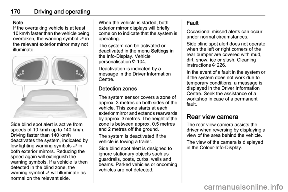
Detection zones The system sensor covers a zone of
approx. 3 metres on both sides of the
vehicle. This zone starts at each
exterior mirror and extends rearwards by approx. 3 metres. The height of the zone is between approx. 0.5 metres
and 2 metres off the ground.
The system is deactivated if the
vehicle is towing a trailer.
Side blind spot alert is designed to ignore stationary objects such as
guardrails, posts, curbs, walls and
beams. Parked vehicles or oncoming
vehicles are not detected.Fault
Occasional missed alerts can occur
under normal circumstances.
Side blind spot alert does not operate when the left or right corners of the
rear bumper are covered with mud,
dirt, snow, ice or slush. Cleaning
instructions 3 226.
In the event of a fault in the system or
if the system does not work due to
temporary conditions, a message is
displayed in the Driver Information
Centre. Seek the assistance of a
workshop in case of a permanent
fault.
Rear view camera The rear view camera assists the
driver when reversing by displaying a
view of the area behind the vehicle.
The view of the camera is displayed
in the Colour-Info-Display.
Page 173 of 261
Driving and operating1719Warning
The rear view camera does not
replace driver vision. Note that
objects that are outside the
camera's field of view and the
advanced parking assist sensors,
e.g. below the bumper or
underneath the vehicle, are not
displayed.
Do not reverse the vehicle by only looking at the Info-Display and
check the surrounding area
behind and around the vehicle
before reversing.
Activation
Rear view camera is automatically
activated when reverse gear is
engaged.
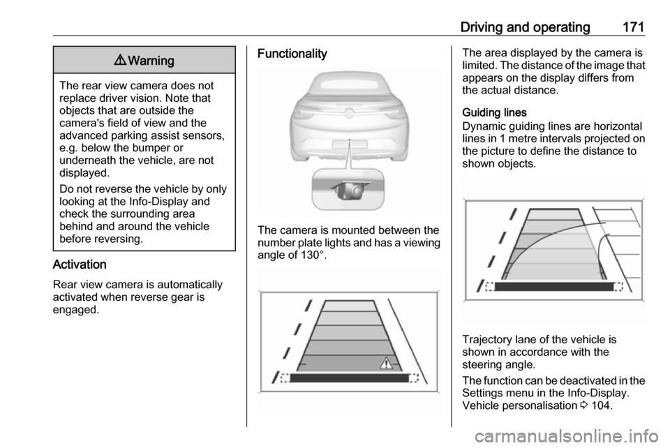
Functionality
The camera is mounted between the
number plate lights and has a viewing angle of 130°.
The area displayed by the camera is
limited. The distance of the image that
appears on the display differs from
the actual distance.
Guiding lines
Dynamic guiding lines are horizontal
lines in 1 metre intervals projected on
the picture to define the distance to
shown objects.
Trajectory lane of the vehicle is
shown in accordance with the
steering angle.
The function can be deactivated in the
Settings menu in the Info-Display.
Vehicle personalisation 3 104.
Page 174 of 261
172Driving and operatingWarning symbols
Warning symbols are indicated as
triangles 9 on the picture, which show
obstacles detected by the rear
sensors of the advanced parking
assist.
Additionally 9 appears on the top line
of the Info-Display with a warning to
check the vehicle surrounding.
The top line of the display can be
cleared by pressing the multifunction
knob.
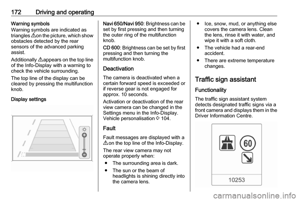
Display settingsNavi 650 /Navi 950 : Brightness can be
set by first pressing and then turning
the outer ring of the multifunction
knob.
CD 600 : Brightness can be set by first
pressing and then turning the
multifunction knob.
Deactivation The camera is deactivated when acertain forward speed is exceeded or
if reverse gear is not engaged for
approx. 10 seconds.
Activation or deactivation of the rear
view camera can be changed in the Settings menu in the Info-Display.
Vehicle personalisation 3 104.
Fault
Fault messages are displayed with a 9 on the top line of the Info-Display.
The rear view camera may not
operate properly when:
● The surrounding area is dark.● The sun or the beam of headlights is shining directly into
the camera lens.● Ice, snow, mud, or anything else covers the camera lens. Clean
the lens, rinse it with water, and
wipe it with a soft cloth.
● The vehicle had a rear-end accident.
● There are extreme temperature changes.
Traffic sign assistant
Functionality
The traffic sign assistant system detects designated traffic signs via a
front camera and displays them in the Driver Information Centre.
Page 175 of 261

Driving and operating173Traffic signs which will be detected
are:Limit and no passing signs ● speed limit
● no passing
● end of speed limit
● end of no passingRoad signs
Beginning and end of:
● motorways
● A-roads
● play streetsAdd-on signs ● additional hints to traffic signs
● restriction of trailer towing
● tractor constraints
● wet warning
● ice warning
● direction arrows
Speed limit signs and no passing
signs are displayed in the Driver
Information Centre until the next
speed limit sign or end of speed limit
is detected or up to a defined sign
timeout.
Indication of multiple signs on the
display is possible.
An exclamation mark in a frame
indicates that there is an add on sign
detected which cannot be recognised
by the system.
The system is active up to a speed of 200 km/h depending on the lighting
conditions. At night the system is
active up to a speed of 160 km/h.
As soon as vehicle speed becomes
slower than 55 km/h the display will
be reset and the content of the traffic
sign page will be cleared, e.g. when
entering a city zone. The next
recognized speed indication will be
displayed.
Display indication
Traffic signs are displayed in the
Traffic sign detection page in the
Driver Information Centre.
Page 178 of 261

176Driving and operatingThe driver assistance systems donot relieve the driver from full
responsibility for vehicle
operation.
Lane departure warning
The lane departure warning system
observes the lane markings between
which the vehicle is driving via a front camera. The system detects lane
changes and warns the driver in the
event of an unintended lane change
via visual and acoustic signals.
Criteria for the detection of an
unintended lane change are:
● no operation of turn signals
● no brake pedal operation
● no active accelerator operation or
speeding-up
● no active steering
If the driver is performing these
actions, no warning will be issued.
Activation
The lane departure warning system is activated by pressing ). The
illuminated LED in the button
indicates that the system is switched
on. When the control indicator ) in
the instrument cluster illuminates
green, the system is ready to operate.
The system is only operable at
vehicle speeds above 56 km/h and if
lane markings are available.
When the system recognises an
unintended lane change, the control
indicator ) changes to yellow and
flashes. Simultaneously a chime
sound is activated.
Deactivation
The system is deactivated by
pressing ), the LED in the button
extinguishes.
At speeds below 56 km/h the system
is inoperable.
Fault
The lane departure warning system
may not operate properly when:
● the windscreen is not clean
● there are adverse environmental conditions like heavy rain, snow,
direct sunlight or shadows
Page 185 of 261
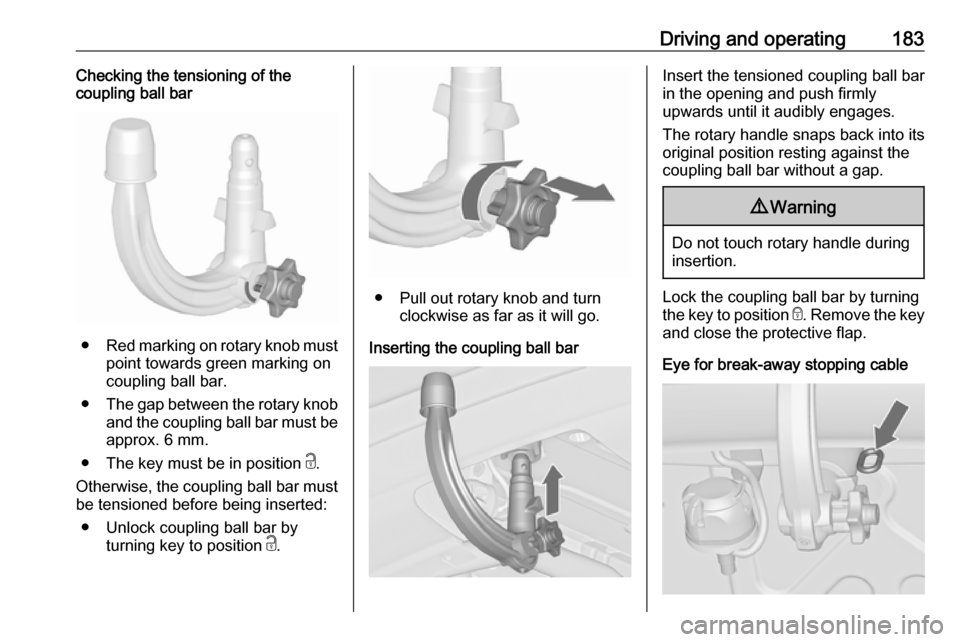
Driving and operating183Checking the tensioning of the
coupling ball bar
● Red marking on rotary knob must
point towards green marking on
coupling ball bar.
● The gap between the rotary knob
and the coupling ball bar must be approx. 6 mm.
● The key must be in position c.
Otherwise, the coupling ball bar must be tensioned before being inserted:
● Unlock coupling ball bar by turning key to position c.
● Pull out rotary knob and turn
clockwise as far as it will go.
Inserting the coupling ball bar
Insert the tensioned coupling ball bar
in the opening and push firmly
upwards until it audibly engages.
The rotary handle snaps back into its
original position resting against the
coupling ball bar without a gap.9 Warning
Do not touch rotary handle during
insertion.
Lock the coupling ball bar by turning
the key to position e. Remove the key
and close the protective flap.
Eye for break-away stopping cable
Page 186 of 261
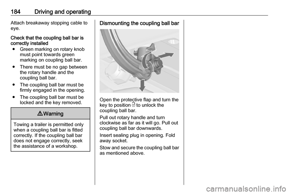
184Driving and operatingAttach breakaway stopping cable to
eye.
Check that the coupling ball bar is correctly installed
● Green marking on rotary knob must point towards green
marking on coupling ball bar.
● There must be no gap between the rotary handle and the
coupling ball bar.
● The coupling ball bar must be firmly engaged in the opening.
● The coupling ball bar must be locked and the key removed.9Warning
Towing a trailer is permitted only
when a coupling ball bar is fitted correctly. If the coupling ball bardoes not engage correctly, seekthe assistance of a workshop.
Dismounting the coupling ball bar
Open the protective flap and turn the
key to position c to unlock the
coupling ball bar.
Pull out rotary handle and turn
clockwise as far as it will go. Pull out coupling ball bar downwards.
Insert sealing plug in opening. Fold away socket.
Stow and secure the coupling ball bar
as mentioned above.
Page 189 of 261
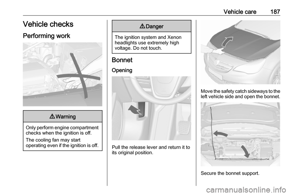
Vehicle care187Vehicle checks
Performing work9 Warning
Only perform engine compartment
checks when the ignition is off.
The cooling fan may start
operating even if the ignition is off.
9 Danger
The ignition system and Xenon
headlights use extremely high
voltage. Do not touch.
Bonnet
Opening
Pull the release lever and return it to
its original position.
Move the safety catch sideways to the left vehicle side and open the bonnet.
Secure the bonnet support.