bulb OPEL COMBO 2010 Owners Manual
[x] Cancel search | Manufacturer: OPEL, Model Year: 2010, Model line: COMBO, Model: OPEL COMBO 2010Pages: 212, PDF Size: 2.49 MB
Page 74 of 212
68 InstrumentsO
Turn signal lamps
Control indicator flashes green.
The control indicator flashes if a turn signal
or the hazard warning flashers are
activated.
Rapid flashing: lamp or associated fuse
has failed.
Replacing bulbs 3151. Fuses 3145.
C
Main beam
Control indicator lights up blue.
It is illuminated when main beam is on and
during headlamp flash 385.
Picture no: 18529s.tif
!
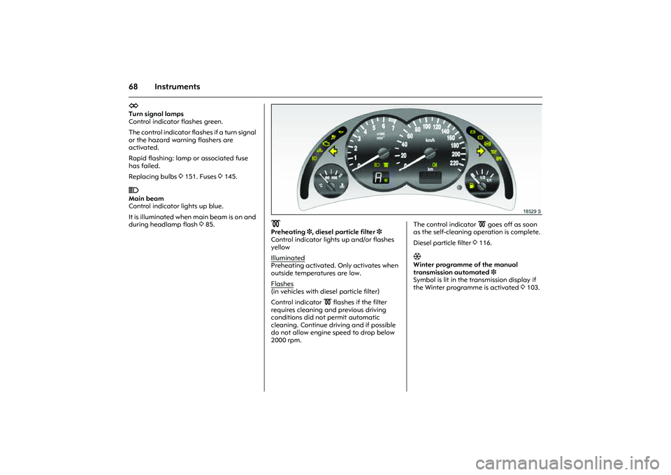
Preheating3, diesel particle filter 3
Control indicator lights up and/or flashes
yellow
Illuminated
Preheating activated. Only activates when
outside temperatures are low.
Flashes
(in vehicles with diesel particle filter)
Control indicator ! flashes if the filter
requires cleaning and previous driving
conditions did not permit automatic
cleaning. Continue driving and if possible
do not allow engine speed to drop below
2000 rpm.
Picture no:
The control indicator ! goes off as soon
as the self-cleaning operation is complete.
Diesel particle filter 3116.T
Winter programme of the manual
transmission automated3
Symbol is lit in the transmission display if
the Winter programme is activated 3103.
Page 133 of 212

127
Driving and operation
Picture no: 13228s.tif
Driving characteristics, towing tips
In the case of trailers/caravans with brakes,
attach breakaway stopping cable to eye.
Before attaching the trailer/caravan,
lubricate the ball of the trailer/caravan
towing device. However, do not lubricate
the ball if a stabiliser, which acts on the
coupling ball, is being used to damp
hunting.
Check caravan/trailer lighting before
starting to drive. The fog tail lamps on the
vehicle are deactivated when towing a
caravan or trailer. Caravans/trailers with LED turn signals
require a provision that make bulb
replacement as with standard bulbs
possible.
Handling is greatly influenced by the
loading of the trailer/caravan. Loads
should therefore be secured so that they
cannot slip and be placed in the centre of
the trailer/caravan if possible, i.e. above
the axle.
In the case of trailers with low driving
stability, do not exceed a speed of
80 km/h; the use of a friction-type
stabiliser is highly recommended.
If the trailer/caravan starts to sway, drive
more slowly, do not attempt to correct the
steering and brake sharply if necessary.
If it is necessary to apply the brakes fully,
depress the brake pedal as hard as
possible.
Remember that the braking distance for
vehicles towing caravans/trailers with and
without brake is always greater than that
for vehicles not towing a caravan/trailer. When driving downhill, drive in the same
gear as if driving uphill and drive at a
similar speed.
Adjust tyre pressure to the value specified
for full load 3121, 3191.
Page 134 of 212
128 Self-help, vehicle careSelf-help, vehicle care
Diesel fuel system, bleeding If the tank is allowed to run dry, the diesel
fuel system must be bled. Turn over the
ignition three times for 15 seconds at a
time. Then start the engine for a maximum
of 40 seconds
1). Repeat this process after
no less than 5 seconds. If the engine fails to
start, seek the assistance of a workshop.
Picture no: 16121s.tif
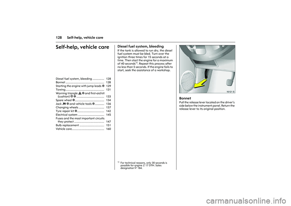
Bonnet Pull the release lever located on the driver’s
side below the instrument panel. Return the
release lever to its original position. Diesel fuel system, bleeding ............... 128
Bonnet .................................................. 128
Starting the engine with jump leads3 129
Towing .................................................. 131
Warning triangle ¨ 3 and first-aid kit
(cushion) + 3.................................... 133
Spare wheel 3...................................... 134
Jack £ 3 and vehicle tools3............ 136
Changing wheels ................................. 137
Tyre repair kit 3................................... 142
Electrical system .................................. 145
Fuses and the most important circuits
they protect ....................................... 147
Bulb replacement ................................ 151
Vehicle care.......................................... 160
1)For technical reasons, only 30 seconds is
possible for engine Z 17 DTH. Sales
designation
3184.
Page 157 of 212
151
Self-help, vehicle care
Bulb replacement Switch off the ignition and switch off the
relevant switch or close the doors.
Only hold a new bulb at the base! Do not
touch the bulb glass with your bare hands.
The replacement bulb must be in
accordance with the data on the base of
the defective bulb. Do not exceed wattage
given on bulb base.
To change the bulbs on the left side, open
the fuse box cover. With the Z 13 DTJ
engine
1), also pull the relay box in front of
the fuse box upwards out of the guides.
Pull off the air hose on the air filter on the
right.
Picture no: 16074s.tif
Halogen headlamp system,
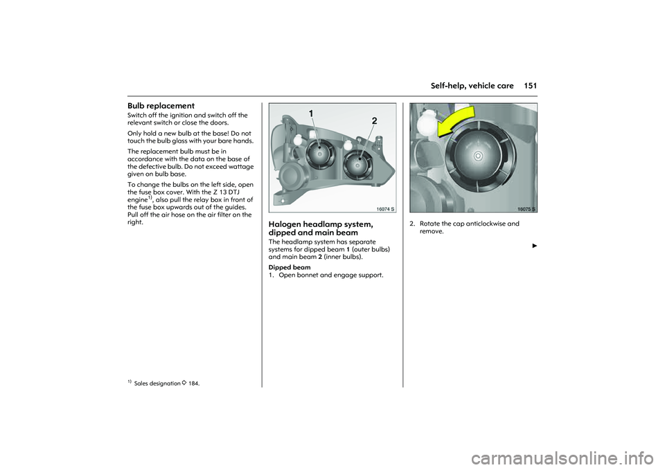
dipped and main beam The headlamp system has separate
systems for dipped beam 1 (outer bulbs)
and main beam 2 (inner bulbs).
Dipped beam
1. Open bonnet and engage support.
Picture no: 16075s.tif
2. Rotate the cap anticlockwise and
remove.
6
1)Sales designation
3184.
Page 158 of 212
152 Self-help, vehicle care
Picture no: 16076s.tif
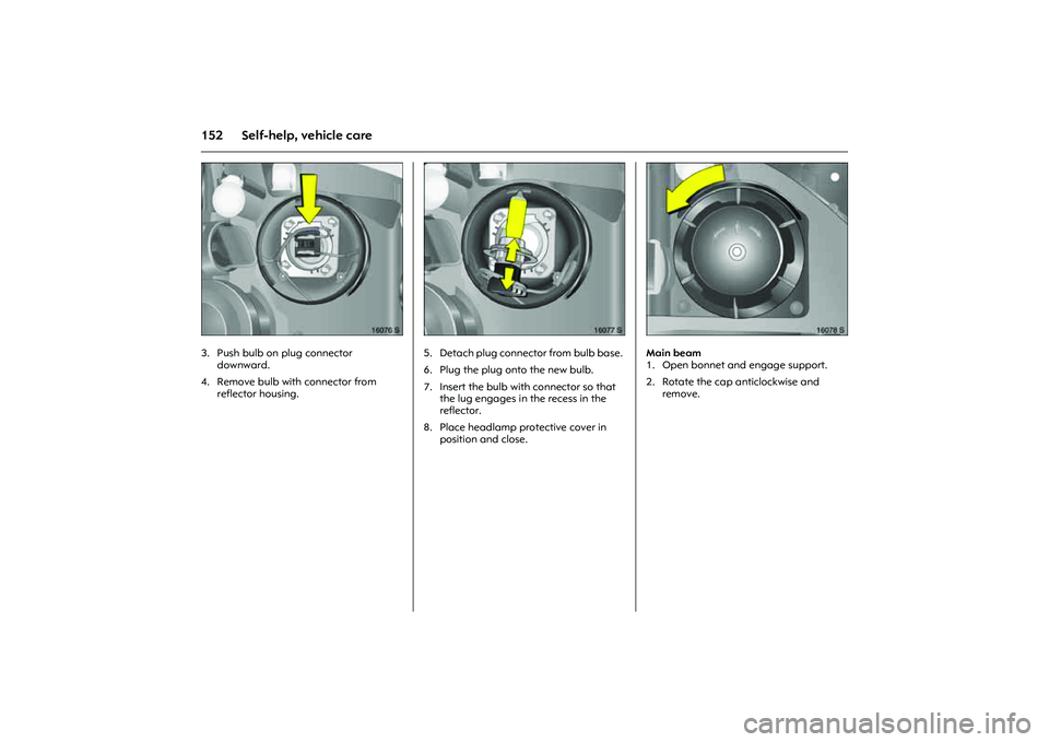
3. Push bulb on plug connector
downward.
4. Remove bulb with connector from
reflector housing.
Picture no: 16077s.tif
5. Detach plug connector from bulb base.
6. Plug the plug onto the new bulb.
7. Insert the bulb with connector so that
the lug engages in the recess in the
reflector.
8. Place headlamp protective cover in
position and close.
Picture no: 16078s.tif
Main beam
1. Open bonnet and engage support.
2. Rotate the cap anticlockwise and
remove.
Page 159 of 212

153
Self-help, vehicle care
Picture no: 16079s.tif
3. Detach plug connector from bulb.
4. Disengage spring wire clip from
retaining lugs by moving it forward and
swivelling it to the side.
Picture no: 16080s.tif
5. Remove bulb from reflector housing.
6. When fitting the new bulb, insert lugs in
the reflector recesses.
7. Engage spring wire clip, plug connector
onto bulb.
8. Place headlamp protective cover in
position and close.
Picture no: 16078s.tif
Parking lamps
1. Open bonnet and engage support.
2. Rotate the main beam headlamp cap
anticlockwise and remove.
3. Detach plug connector from main
beam bulb.
Page 160 of 212
154 Self-help, vehicle care
Picture no: 16081s.tif
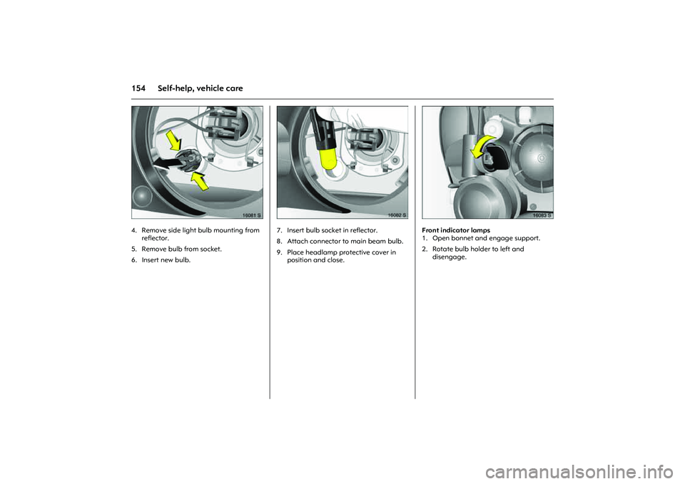
4. Remove side light bulb mounting from
reflector.
5. Remove bulb from socket.
6. Insert new bulb.
Picture no: 16082s.tif
7. Insert bulb socket in reflector.
8. Attach connector to main beam bulb.
9. Place headlamp protective cover in
position and close.
Picture no: 16083s.tif
Front indicator lamps
1. Open bonnet and engage support.
2. Rotate bulb holder to left and
disengage.
Page 161 of 212
155
Self-help, vehicle care
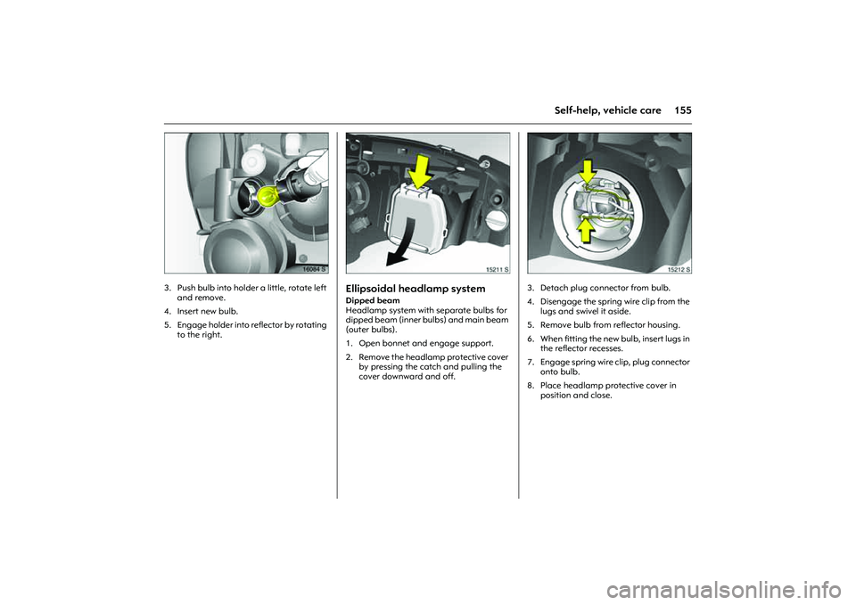
Picture no: 16084s.tif
3. Push bulb into holder a little, rotate left
and remove.
4. Insert new bulb.
5. Engage holder into reflector by rotating
to the right.
Picture no: 15211s.tif
Ellipsoidal headlamp systemDipped beam
Headlamp system with separate bulbs for
dipped beam (inner bulbs) and main beam
(outer bulbs).
1. Open bonnet and engage support.
2. Remove the headlamp protective cover
by pressing the catch and pulling the
cover downward and off.
Picture no: 15212s.tif
3. Detach plug connector from bulb.
4. Disengage the spring wire clip from the
lugs and swivel it aside.
5. Remove bulb from reflector housing.
6. When fitting the new bulb, insert lugs in
the reflector recesses.
7. Engage spring wire clip, plug connector
onto bulb.
8. Place headlamp protective cover in
position and close.
Page 162 of 212
156 Self-help, vehicle care
Picture no: 15213s.tif
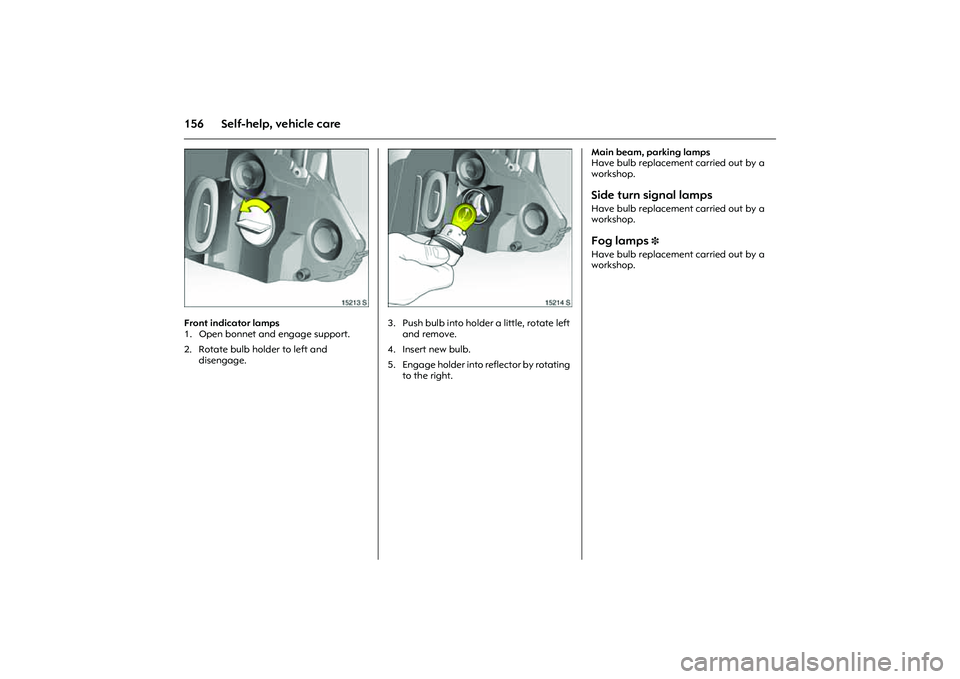
Front indicator lamps
1. Open bonnet and engage support.
2. Rotate bulb holder to left and
disengage.
Picture no: 15214s.tif
3. Push bulb into holder a little, rotate left
and remove.
4. Insert new bulb.
5. Engage holder into reflector by rotating
to the right. Main beam, parking lamps
Have bulb replacement carried out by a
workshop.
Side turn signal lamps Have bulb replacement carried out by a
workshop. Fog lamps
3
Have bulb replacement carried out by a
workshop.
Page 163 of 212

157
Self-help, vehicle care
Picture no: 12449s.tif
Tail lamps 1. Disengage cover by pressing retaining
lugs and remove.
Picture no: 13725s.tif
2. Detach plug connector from bulb
mounting.
3. Grip the bulb housing from the outside,
slacken the two knurled nuts using the
wheel bolt spanner 3 and unscrew by
hand.
4. Detach bulb housing.
5. Press retaining lugs on bulb mounting
together and remove bulb mounting, as
shown in illustration 13726 S.
Picture no: 13726s.tif
Lamps from top to bottom:
6. Remove bulb from socket.
7. Insert a new bulb. Engage the bulb
mounting in the bulb housing. Insert the
bulb housing into the vehicle body.
Screw the fixing nuts onto setscrews by
hand and tighten. Engage the plug
connector. Place the cover in position
and close. Reversing light/brake light
Turn signal lamp
Reversing light
Fog tail lamp (country-specific version:
fog tail lamp at one side only).