clock OPEL COMBO E 2019.1 Manual user
[x] Cancel search | Manufacturer: OPEL, Model Year: 2019.1, Model line: COMBO E, Model: OPEL COMBO E 2019.1Pages: 283, PDF Size: 10.57 MB
Page 31 of 283

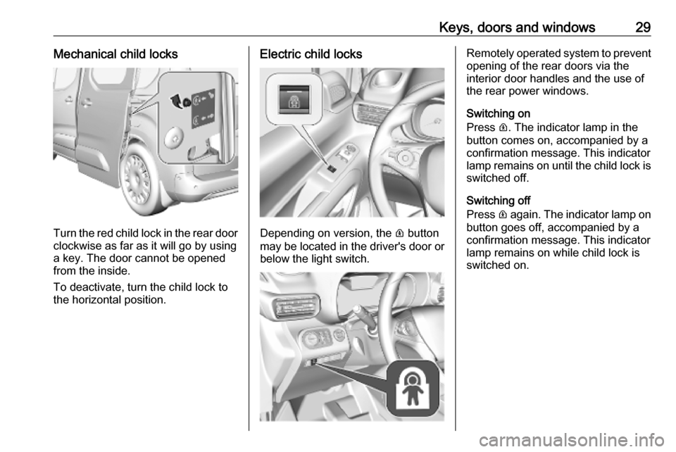
Keys, doors and windows29Mechanical child locks
Turn the red child lock in the rear doorclockwise as far as it will go by using
a key. The door cannot be opened
from the inside.
To deactivate, turn the child lock to
the horizontal position.
Electric child locks
Depending on version, the R button
may be located in the driver's door or
below the light switch.
Remotely operated system to prevent
opening of the rear doors via the
interior door handles and the use of
the rear power windows.
Switching on
Press R. The indicator lamp in the
button comes on, accompanied by a confirmation message. This indicator
lamp remains on until the child lock is
switched off.
Switching off
Press R again. The indicator lamp on
button goes off, accompanied by a
confirmation message. This indicator
lamp remains on while child lock is
switched on.
Page 37 of 283

Keys, doors and windows35Vehicle security
Anti-theft locking system9 Warning
Do not use the system if there are
people in the vehicle! The doorscannot be unlocked from the
inside.
The system deadlocks all the doors. All doors must be closed otherwise
the system cannot be activated.
Unlocking the vehicle disables the
mechanical anti-theft locking system.
This is not possible with the central
locking button.
Activating
Simple key: Insert the key and turn it
clockwise twice within 5 seconds.
Remote control: Press N on the radio
remote control twice within five
seconds.
Electronic key: Press twice with a
finger or thumb on one of the door
handles (at the markings) within five seconds
Anti-theft alarm system The anti-theft alarm system is
combined with the anti-theft locking
system.
It monitors: ● doors, tailgate, bonnet
● passenger compartment including adjoining load
compartment
Activation
Ignition must be switched off. All
doors must be closed and the
electronic key must not remain in the
vehicle. Otherwise the system cannot
be activated.
● Radio remote control: Monitoring
of doors, tailgate and bonnet is
self-activated 5 seconds after
locking the vehicle by pressing e.
Monitoring of passenger
compartment including adjoiningload compartment is self-
activated 45 seconds after
locking the vehicle by pressing e.
● Electronic key system: Monitoring of doors, tailgate and
bonnet is self-activated
5 seconds after locking the
vehicle by pressing with a finger
or thumb on one of the front door handles at the markings.
Monitoring of passenger
compartment including adjoining
load compartment is self-
activated 45 seconds after
locking the vehicle by pressing with a finger or thumb on one of
the front door handles at the
markings.
Activation is confirmed by the flashing of the status LED and coming on of
the turn lights for a short time.
If a door or the tailgate is not correctly
closed and the vehicle is locked via
remote control or electronic key
system, the vehicle remains
unlocked. However, the anti-theft
alarm system will be activated after
45 seconds.
Page 91 of 283

Instruments and controls89Instruments and
controlsControls ....................................... 90
Steering wheel adjustment ........90
Steering wheel controls .............90
Heated steering wheel ...............90
Horn ........................................... 91
Windscreen wiper and washer ..91
Rear window wiper and washer ...................................... 93
Outside temperature ..................93
Clock ......................................... 94
Power outlets ............................. 94
Inductive charging .....................95
Cigarette lighter ......................... 96
Ashtrays .................................... 97
Warning lights, gauges and indi‐ cators ........................................... 97
Instrument cluster ......................97
Speedometer ............................. 99
Odometer ................................ 100
Trip odometer .......................... 100
Tachometer ............................. 100
Fuel gauge .............................. 101
Engine coolant temperature gauge ..................................... 101Engine oil level monitor...........101
Service display ........................ 102
Control indicators ....................102
Turn lights ................................ 103
Seat belt reminder ...................103
Airbag and belt tensioners .......103
Airbag deactivation ..................104
Charging system .....................104
Malfunction indicator light ........104
Service vehicle soon ...............105
Stop engine ............................. 105
System check .......................... 105
Brake and clutch system .........105
Parking brake .......................... 105
Electric parking brake ..............105
Electric parking brake fault ......106
Antilock brake system (ABS) ...106
Gear shifting ............................ 106
Descent control system ...........106
Lane keep assist .....................106
Electronic Stability Control and Traction Control system .........107
Engine coolant temperature ....107
Preheating ............................... 107
Exhaust filter ............................ 107
AdBlue ..................................... 107
Deflation detection system ......108
Engine oil pressure ..................108
Low fuel ................................... 108
Autostop .................................. 108Exterior light............................ 109
High beam ............................... 109
Low beam ................................ 109
High beam assist .....................109
LED headlights ........................ 109
Front fog lights ......................... 109
Rear fog light ........................... 109
Rain sensor ............................. 109
Cruise control .......................... 109
Adaptive cruise control ............109
Vehicle detected ahead ...........109
Side blind spot alert .................110
Active emergency braking .......110
Speed limiter ........................... 110
Door open ................................ 110
Displays ..................................... 110
Driver Information Centre ........110
Info Display .............................. 113
Head-up display ......................114
Rear view display ....................116
Vehicle messages ......................117
Warning chimes .......................117
Battery voltage ........................ 117
Vehicle personalisation ..............118
Page 96 of 283

94Instruments and controls9Warning
The road surface may already be
icy even though the display
indicates a few degrees above
0 °C.
Clock
Date and time are shown in the InfoDisplay.
The adjustment of date and time is
described in the Infotainment Manual.
Info Display 3 113.
Power outlets
A 12 V power outlet is located behind
the storage cover. Push cover
upwards to open.
Depending on the version, the 12 V
power outlet may be freely
accessible.
At the right side of the load
compartment, another 12 V power
outlet may be located.
Do not exceed the maximum power
consumption of 120 W.
A 230 V power outlet may be located
on the lower side of the centre
console in the front passenger
compartment.
Do not exceed the maximum power
consumption of 150 W.
With ignition off, the power outlets are
deactivated. Additionally the power
outlets are deactivated in the event of
low vehicle battery voltage.
Electrical accessories that are
connected must comply with the
electromagnetic compatibility
requirements laid down in
DIN VDE 40 839.
Page 135 of 283

Climate control133clockwise:increaseanticklockwise:decrease
Air recirculation system u
Press u to activate air recirculation
mode. The LED in the button
illuminates to indicate activation.
Press u again to deactivate air
recirculation mode.
9 Warning
The exchange of fresh air is
reduced in air recirculation mode.
In operation without cooling the air humidity increases, so the
windows may mist up from inside.
The quality of the passenger
compartment air deteriorates,
which may cause the vehicle
occupants to feel drowsy.
In warm and very humid ambient air conditions, the windscreen may mist
up from outside when cold air is
directed towards it. If windscreen
mists up from outside, activate
windscreen wiper and deactivate l.
Demisting and defrosting
● Press l: the air distribution is
directed towards the windscreen.
● Set temperature controller n to
warmest level.
● Set fan speed x to highest level.
● Switch on heated rear window e.
● Open side air vents as required and direct them towards the doorwindows.
Heated rear window, windscreen and exterior mirrors b 3 43.
Heated seats ß 3 51.
Air conditioning system
Controls for: ● temperature n
● air distribution l, M and K
● fan speed x
Page 136 of 283

134Climate control● cooling A/C
● air recirculation u
● heated rear window and exterior mirrors e
Heated rear window e3 43.
Heated exterior mirrors e3 39.
Temperature n
Adjust the temperature by turning n to
the desired temperature.HI:warmLO:cold
Heating will not be fully effective until
the engine has reached normal
operating temperature.
Air distribution l,
M ,
K
l:to windscreen and front door
windowsM:to head area via adjustable air
ventsK:to foot well
All combinations are possible.
Fan speed x
Adjust the air flow by turning x to the
desired speed.clockwise:increaseanticlockwise:decrease
Cooling A/C
Press A/C to switch on cooling. The
LED in the button illuminates to
indicate activation. Cooling is only
functional when the engine is running and fan is switched on.
Press A/C again to switch off cooling.
The air conditioning system cools and
dehumidifies (dries) as soon as the
outside temperature is slightly above
the freezing point. Therefore,
condensation may form and drip from
under the vehicle.
If no cooling or drying is required,
switch off the cooling system for fuel
saving reasons.
Activated cooling may inhibit
Autostops. Stop-start system 3 149.
Air recirculation system u
Press u to activate air recirculation
mode. The LED in the button
illuminates to indicate activation.
Press u again to deactivate air
recirculation mode.
Page 159 of 283

Driving and operating157The vehicle must be parked on a level
surface.
The filler neck for AdBlue is located
behind the fuel filler flap, which is located at right rear side of the
vehicle.
If the vehicle is equipped with an
electronic key system, the fuel filler
flap can only be opened if the vehicle is unlocked.
1. Remove key from ignition switch.
2. Close all doors to avoid ammonia fumes entering the interior of the
vehicle.
3. Release the fuel filler flap by pushing the flap 3 206.4. Unscrew protective cap from the
filler neck.
5. Open AdBlue canister.
6. Mount one end of the hose on the
canister and screw the other end
on the filler neck.
7. Lift the canister until it is empty, or
until the flow from the canister has stopped. This can take up to five
minutes.
8. Place the canister on the ground to empty the hose, wait 15 s.
9. Unscrew the hose from the filler neck.
10. Mount the protective cap and turn
clockwise until it engages.
Note
Dispose of AdBlue canister
according to environmental
requirements. Hose can be reused
after flushing with clear water before
AdBlue dries out.Automatic transmission
The automatic transmission permits
automatic gearshifting (automatic
mode) or manual gearshifting
(manual mode).
Manual shifting is possible in manual
mode by pressing M next to the
selector wheel and shifting with the paddles + and - on the steering wheel
3 158.
Transmission display
The mode or selected gear is shown
in the Driver Information Centre.
Page 209 of 283

Driving and operating207Caution
In case of misfuelling, do not
switch on ignition.
Fuel filler flap is located at left rear
side of vehicle.
If the vehicle is equipped with an
electronic key system, the fuel filler
flap can only be opened if the vehicle
is unlocked. Depending on the
version, release the fuel filler flap by
pushing the flap or pulling at the right bottom corner.
Petrol and diesel refuelling
Depending on the version, place the
key in the lock and unlock the cap.
To open, turn the cap slowly
anticlockwise.
The fuel filler cap can be attached to
the hook on the fuel filler flap.
Place the nozzle in straight position to the filler neck and press with slight
force to insert.
To refuel, switch on pump nozzle.
After the automatic cut-off, the tank can be topped up by operating the
pump nozzle a maximum of two more
times.
Caution
Wipe off any overflowing fuel
immediately.
To close, turn the fuel filler cap
clockwise until it clicks.
Close the flap and allow it to engage.
Fuel filler cap
Only use genuine fuel filler caps.
Diesel-engined vehicles have special fuel filler caps.
Page 224 of 283

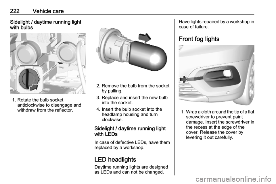
222Vehicle careSidelight / daytime running light
with bulbs
1. Rotate the bulb socket anticlockwise to disengage and
withdraw from the reflector.
2. Remove the bulb from the socket by pulling.
3. Replace and insert the new bulb into the socket.
4. Insert the bulb socket into the headlamp housing and turn
clockwise.
Sidelight / daytime running light
with LEDs
In case of defective LEDs, have them replaced by a workshop.
LED headlights Daytime running lights are designedas LEDs and can not be changed.
Have lights repaired by a workshop in
case of failure.
Front fog lights
1. Wrap a cloth around the tip of a flat
screwdriver to prevent paint
damage. Insert the screwdriver in
the recess at the edge of the
cover. Release the cover by
levering it out carefully.
Page 225 of 283

Vehicle care223
2. Unscrew and remove the twoscrews and remove the lightassembly to the front.
3. Turn the bulb socket anticlockwise and remove it from
the light assembly.
4. Disengage the plug connector by pulling the retaining lug.
5. Remove and replace the bulb unit
and attach the plug connector.
Note that the bulb and the socket
are one unit and have to be
changed together.
6. Insert the bulb socket into the light
assembly by turning clockwise
and engage.
7. Mount the light assembly by tightening the two screws.
8. Attach and engage the cover.
Front turn lights
1. Rotate the bulb socket anticlockwise to disengage and
withdraw from the reflector.