change time OPEL CORSA F 2020 Manual user
[x] Cancel search | Manufacturer: OPEL, Model Year: 2020, Model line: CORSA F, Model: OPEL CORSA F 2020Pages: 229, PDF Size: 21.14 MB
Page 150 of 229
148Driving and operatingActive side blind spot detection
operates when the vehicle speed is
between 65 and 140 km/h.
Functionality
When steering towards the detected
vehicle is attemped, the driver will
then notice a turning movement of the
steering wheel towards the opposite
side. Turn steering wheel in the same direction if the system does not steer
sufficiently.
The system also intervenes even if
the turn lights have been activated.
Panoramic view system
This system allows views of the
vehicle's surroundings to be
displayed as a nearly 180° picture in
the Info Display, like a bird's eye view.
The system uses: ● rear camera, installed in the rear bumper
● ultrasonic parking sensors in the rear bumper
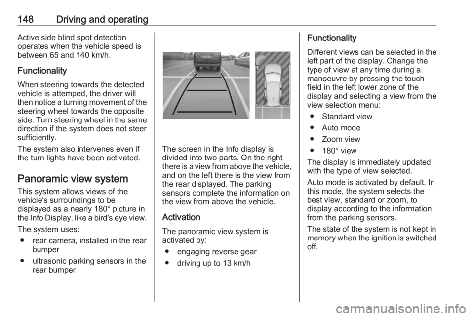
The screen in the Info display is
divided into two parts. On the right
there is a view from above the vehicle,
and on the left there is the view from
the rear displayed. The parking
sensors complete the information on
the view from above the vehicle.
Activation
The panoramic view system is
activated by:
● engaging reverse gear
● driving up to 13 km/h
Functionality
Different views can be selected in the left part of the display. Change the
type of view at any time during a
manoeuvre by pressing the touch
field in the left lower zone of the
display and selecting a view from the
view selection menu:
● Standard view
● Auto mode
● Zoom view
● 180° view
The display is immediately updated
with the type of view selected.
Auto mode is activated by default. In
this mode, the system selects the
best view, standard or zoom, to
display according to the information
from the parking sensors.
The state of the system is not kept in
memory when the ignition is switched
off.
Page 154 of 229

152Driving and operating
The system recognises the traffic
signs above and displays them in the
Driver Information Centre.
9 Warning
The actual traffic sign always
takes priority over the traffic sign displayed in the Driver Information Centre.
If the vehicle enters a road of whichthe entry is prohibited, the no entry
traffic symbol and a warning message are displayed in the Driver
Information Centre. If the system
detects one of the other traffic signs,
the respective traffic sign is displayed
in the Driver Information Centre.
Speed limiter 3 122
Cruise control 3 120
Adaptive cruise control 3 124
Lane keep assist
Lane keep assist supports the driver
to avoid unintended leaving of the
lane. The front camera observes road
edges, as well as the lane markings
between which the vehicle is driving.
If the vehicle approaches a road edge or a lane marking, the steering wheel
is gently turned to position so that the
vehicle turns back into the lane. The
driver will then notice a turning
movement of the steering wheel. Turn steering wheel in same direction, if
the system does not steer sufficiently.
Turn steering wheel gently into
opposite direction, if lane change is
intended.
When the system steers to correct the trajectory of the vehicle, L flashes
yellow in the instrument cluster.
Unintended lane departure is not
assumed by the system when the turn lights are operated and during few
seconds after turn lights have been
switched off.Note
The system may be switched off if it
detects lanes which are too narrow,
too wide or too curved.
Following preconditions have to be
fulfilled:
● vehicle speed must be between 65 km/h and 180 km/h
● the driver must hold the steering wheel
● the turn lights are not activated
● the electronic stability control is activated and not in operation
● the vehicle is not connected to a trailer or an electric bicycle carrier
● normal driving behaviour (system
detects dynamic driving style, i.e. pressure on the brake or
accelerator pedal)
● roads with good lane markings ● no spare wheel is used
● the driver is not taking the hands off the steering wheel for a longer
time period
● the vehicle is not driven in a tight
corner
Page 160 of 229
158Driving and operatingPetrol and diesel refuelling
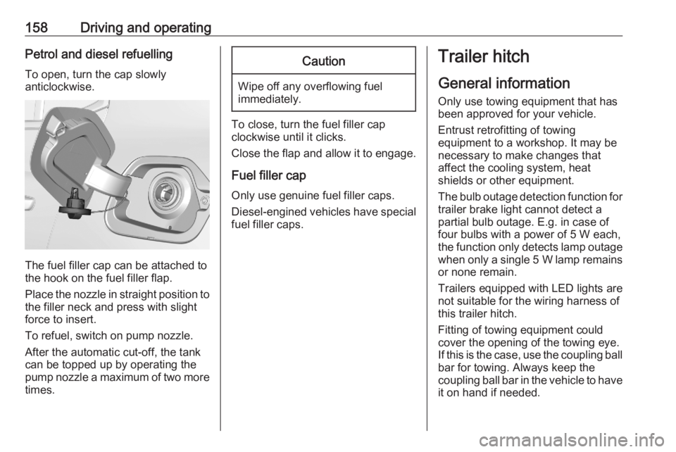
To open, turn the cap slowly
anticlockwise.
The fuel filler cap can be attached to
the hook on the fuel filler flap.
Place the nozzle in straight position to the filler neck and press with slight
force to insert.
To refuel, switch on pump nozzle.
After the automatic cut-off, the tank can be topped up by operating the
pump nozzle a maximum of two more
times.
Caution
Wipe off any overflowing fuel
immediately.
To close, turn the fuel filler cap
clockwise until it clicks.
Close the flap and allow it to engage.
Fuel filler cap
Only use genuine fuel filler caps.
Diesel-engined vehicles have special fuel filler caps.
Trailer hitch
General information
Only use towing equipment that has
been approved for your vehicle.
Entrust retrofitting of towing
equipment to a workshop. It may be
necessary to make changes that
affect the cooling system, heat
shields or other equipment.
The bulb outage detection function for
trailer brake light cannot detect a
partial bulb outage. E.g. in case of
four bulbs with a power of 5 W each,
the function only detects lamp outage when only a single 5 W lamp remains
or none remain.
Trailers equipped with LED lights are
not suitable for the wiring harness of
this trailer hitch.
Fitting of towing equipment could
cover the opening of the towing eye.
If this is the case, use the coupling ball
bar for towing. Always keep the
coupling ball bar in the vehicle to have it on hand if needed.
Page 164 of 229
162Vehicle careCaution
When transporting the vehicle on
a train or on a recovery vehicle, the
mud flaps might be damaged.
Vehicle storage
Storage for a long period of time
If the vehicle is to be stored for several months:
● Wash and wax the vehicle.
● Have the wax in the engine compartment and underbody
checked.
● Clean and preserve the rubber seals.
● Fill up fuel tank completely.
● Change the engine oil.
● Drain the washer fluid reservoir.
● Check the coolant antifreeze and
corrosion protection.
● Adjust tyre pressure to the value specified for full load.
● Park the vehicle in a dry, wellventilated place. Engage first or
reverse gear or set selector lever
to P. Prevent the vehicle from
rolling.
● Do not apply the parking brake.
● Open the bonnet, close all doors and lock the vehicle.
● Disconnect the clamp from the negative terminal of the vehicle
battery. Note that all systems are
not functional, e.g. anti-theft
alarm system.
Putting back into operation
When the vehicle is to be put back into operation:
● Connect the clamp to the negative terminal of the vehicle
battery. Initialise the power
windows 3 23.
● Check tyre pressure.
● Fill up the washer fluid reservoir.
● Check the engine oil level.
● Check the coolant level.
● Fit the number plate if necessary.End-of-life vehicle recovery
Information on end-of-life vehicle
recovery centres and the recycling of
end-of-life vehicles is available on our website, where legally required. Only
entrust this work to an authorised
recycling centre.
Page 173 of 229
Vehicle care171
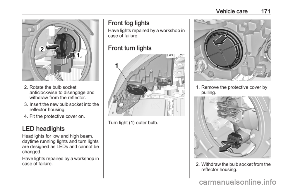
2. Rotate the bulb socketanticlockwise to disengage and
withdraw from the reflector.
3. Insert the new bulb socket into the
reflector housing.
4. Fit the protective cover on.
LED headlights Headlights for low and high beam,
daytime running lights and turn lights
are designed as LEDs and cannot be
changed.
Have lights repaired by a workshop in
case of failure.
Front fog lights
Have lights repaired by a workshop in case of failure.
Front turn lights
Turn light ( 1) outer bulb.
1. Remove the protective cover by
pulling.
2.Withdraw the bulb socket from the
reflector housing.
Page 183 of 229
Vehicle care181After adjusting tyre pressure initialise
system to extinguish the control
indicator and restart system.
If the failure continues to be
displayed, contact a workshop. The
system is inoperable when ABS or
ESC has a malfunction or a
temporary spare wheel is used. Once
the tyre has been refitted, check the
tyre pressure with cold tyres and
initialise the system.Caution
Deflation detection system warns
just about low tyre pressure
condition and does not replace
regular tyre maintenance by the
driver.
System initialisation
After tyre pressure correction or
wheel change, the system must be
initialised to learn new circumference
reference values:
1. Always ensure that all four tyres have correct tyre pressure3 210.
2. Apply parking brake. 3. Initialise the system via the Info Display 3 75.
4. Reset is confirmed by pop-up indication.
After initialisation system
automatically calibrates to new tyre
pressures during driving. After longer
drive the system will adopt and
monitor new pressures.
Always check tyre pressure with cold
tyres.
System has to be reinitialised when: ● Tyre pressure has been changed
● Load condition has been changed
● Wheels have been swapped or exchanged
The system will not warn
instantaneously on a tyre blow out or
a rapid deflation. This is due to
required calculation time.Tread depth
Check tread depth at regular
intervals.
Tyres should be replaced for safety
reasons at a tread depth of 2-3 mm
(4 mm for winter tyres).
For safety reasons, it is
recommended that the tread depth of
the tyres on one axle should not vary
by more than 2 mm.
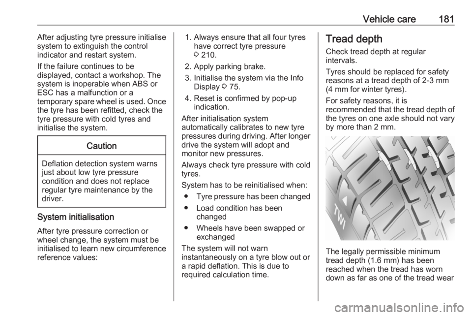
The legally permissible minimum
tread depth (1.6 mm) has been
reached when the tread has worn
down as far as one of the tread wear
Page 189 of 229

Vehicle care187
Rear arm position of the lifting
platform centrically under the relevant vehicle jacking point.
Front arm position of the lifting
platform centrically under the relevant vehicle jacking point.
Spare wheel The spare wheel can be classified as
a temporary spare wheel depending
on the size compared to the other
mounted wheels and country
regulations. In this case a permissible maximum speed applies, even
though no label at the spare wheel
indicates this.
Only mount one temporary spare
wheel. Do not drive faster than
80 km/h. Take curves slowly. Do not
use for a long period of time.Caution
The use of a spare wheel that is smaller than the other wheels or in combination with winter tyres
could affect driveability. Have the defective tyre replaced as soon as
possible.
The spare wheel is located in the load
compartment beneath the floor
covering.
To remove: 1. Open the floor cover 3 51.
2. The temporary spare wheel is secured with a wing nut. Unscrew
nut and take out the spare wheel.
3. When, after a wheel change, no wheel is placed in the spare wheelwell, tighten the wing nut and
close floor cover.
4. After wheel change back to full size wheel, place the temporary
spare wheel outside up in the well
and secure with the wing nut.
Page 220 of 229
218Customer informationbreakdown services) can read the
data from the vehicle. The same
applies to warranty work and quality
assurance measures.
Data is generally read via the OBD
(On-Board Diagnostics) port
prescribed by law in the vehicle. The operating data read documents the
technical condition of the vehicle or
individual components and assists
with fault diagnosis, compliance with
warranty obligations and quality
improvement. This data, in particular
information on component stress,
technical events, operator errors and
other faults, is transmitted to the
manufacturer where appropriate,
together with the vehicle identification
number. The manufacturer is also
subject to product liability. The
manufacturer potentially also uses
operating data from vehicles for
product recalls. This data can also be used to check customer warranty and
guarantee claims.
Fault memories in the vehicle can be
reset by a service company when
carrying out servicing or repairs or at
your request.Comfort and infotainment
functions
Comfort settings and custom settings can be stored in the vehicle and
changed or reset at any time.
Depending on the equipment level in
question, these include
● seat and steering wheel position settings
● chassis and air conditioning settings
● custom settings such as interior lighting
You can input your own data in the
infotainment functions for your
vehicle as part of the selected
features.
Depending on the equipment level in
question, these include
● multimedia data such as music, videos or photos for playback in
an integrated multimedia system
● address book data for use with an
integrated hands-free system or
an integrated navigation system● input destinations
● data on the use of online services
This data for comfort and
infotainment functions can be stored
locally in the vehicle or be kept on a
device that you have connected to the
vehicle ( e.g. a smartphone, USB stick
or MP3 player). Data that you have
input yourself can be deleted at any
time.
This data can only be transmitted out
of the vehicle at your request,
particularly when using online
services in accordance with the
settings selected by you.
Smartphone integration, e.g.
Android Auto or Apple CarPlay
If your vehicle is equipped
accordingly, you can connect your
smartphone or another mobile device to the vehicle so that you can control
it via the controls integrated in the
vehicle. The smartphone image and
sound can be output via the
multimedia system in this case. At the
same time, specific information is
transmitted to your smartphone.
Depending on the type of integration,