remove OPEL CROSSLAND X 2019 Manual user
[x] Cancel search | Manufacturer: OPEL, Model Year: 2019, Model line: CROSSLAND X, Model: OPEL CROSSLAND X 2019Pages: 263, PDF Size: 8.11 MB
Page 183 of 263
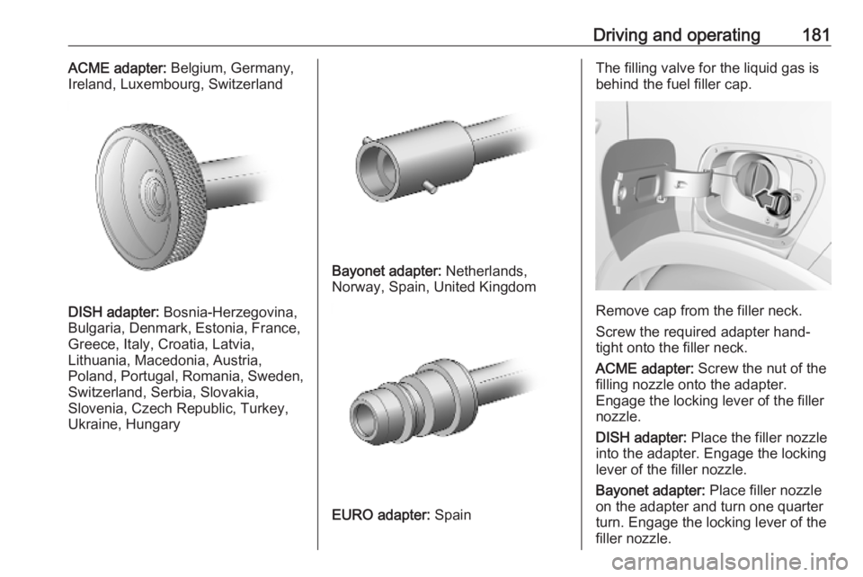
Driving and operating181ACME adapter: Belgium, Germany,
Ireland, Luxembourg, Switzerland
DISH adapter: Bosnia-Herzegovina,
Bulgaria, Denmark, Estonia, France,
Greece, Italy, Croatia, Latvia,
Lithuania, Macedonia, Austria,
Poland, Portugal, Romania, Sweden,
Switzerland, Serbia, Slovakia,
Slovenia, Czech Republic, Turkey,
Ukraine, Hungary
Bayonet adapter: Netherlands,
Norway, Spain, United Kingdom
EURO adapter: Spain
The filling valve for the liquid gas is
behind the fuel filler cap.
Remove cap from the filler neck.
Screw the required adapter hand-
tight onto the filler neck.
ACME adapter: Screw the nut of the
filling nozzle onto the adapter.
Engage the locking lever of the filler
nozzle.
DISH adapter: Place the filler nozzle
into the adapter. Engage the locking
lever of the filler nozzle.
Bayonet adapter: Place filler nozzle
on the adapter and turn one quarter
turn. Engage the locking lever of the
filler nozzle.
Page 184 of 263
182Driving and operatingEURO adapter: Press the filler nozzle
onto the adapter. Engage the locking
lever of the filler nozzle.
Press the button of the liquid gas
supply point. The filling system stops
or begins to run slowly when 80% of
the tank volume is reached
(maximum fill level).
Release button on filling system to stop the filling process. Release the
locking lever and remove the filler
nozzle. A small quantity of liquid gas
can escape.
Remove adapter and stow in vehicle.
Fit protective cap to prevent the
penetration of foreign bodies into the
filler opening and the system.9 Warning
Due to the system design, an
escape of liquid gas after
releasing the locking lever is
unavoidable. Avoid inhaling.
9 Warning
The liquid gas tank may only be
filled to 80% for safety reasons.
The multivalve on the liquid gas tank
automatically limits the fill quantity. If
a larger quantity is added, we
recommend not exposing the vehicle
to the sun until the excess amount
has been used up.
12 minutes after switching off the
ignition the system of the fuel-filling
turns off. To restart it turn the ignition
on and then off again.
Fuel filler cap Only use genuine fuel filler caps.Diesel-engined vehicles have special
fuel filler caps.
Trailer hitch
General information
The factory-fitted towing equipment is
folded up under the rear bumper
fascia.
Entrust retrofitting of towing
equipment to a workshop. It may be
necessary to make changes that
affect the cooling system, heat
shields or other equipment. Only use
towing equipment that has been
approved for your vehicle.
To avoid vehicle damage, the power
tailgate cannot be operated with the
radio remote control when a trailer is
electrically connected.
The bulb outage detection function for trailer brake light cannot detect a
partial bulb outage. E.g. in case of
four bulbs with a power of 5 W each,
the function only detects lamp outage when only a single 5 W lamp remains
or none remain.
Trailers equipped with LED lights are
not suitable for the wiring harness of
this trailer hitch.
Page 186 of 263

184Driving and operatingRear axle load
When the trailer is coupled and the
towing vehicle fully loaded, the
permissible rear axle load (see
identification plate or vehicle
documents) may be exceeded by
60 kg , the gross vehicle weight rating
must not be exceeded. If the
permissible rear axle load is
exceeded, a maximum speed of
100 km/h applies.
Towing equipmentCaution
When operating without a trailer,
remove the coupling ball bar.
Stowage of coupling ball bar
The bag with the coupling ball bar is
stowed on the rear floor cover in the
load compartment.
Place the strap through the rear right
lashing eye, wrap around twice and
tighten the strap to secure the bag.
Fitting the coupling ball bar
Swivel the connecting socket
downwards. Remove the sealing plug from the opening for the coupling ball
bar and stow it.
Checking the tensioning of the
coupling ball bar
● Red marking on rotary knob must
point towards green marking on
coupling ball bar.
● The gap between the rotary knob
and the coupling ball bar must be approx. 6 mm.
● The key must be in position c.
Otherwise, the coupling ball bar must
be tensioned before being inserted:
Page 187 of 263

Driving and operating185● Unlock coupling ball bar byturning key to position c.
● Pull out rotary knob and turn
clockwise as far as it will go.
Inserting the coupling ball bar
Insert the tensioned coupling ball bar
in the opening and push firmly
upwards until it audibly engages.
The rotary handle snaps back into its
original position resting against the
coupling ball bar without a gap.
9 Warning
Do not touch rotary handle during
insertion.
Lock the coupling ball bar by turning
the key to position e. Remove the key
and close the protective flap.
Eye for break-away stopping cable
Attach breakaway stopping cable to
eye.
Check that the coupling ball bar is correctly installed
● Green marking on rotary knob must point towards green
marking on coupling ball bar.
● There must be no gap between the rotary handle and the
coupling ball bar.
● The coupling ball bar must be firmly engaged in the opening.
● The coupling ball bar must be locked and the key removed.
Page 196 of 263

194Vehicle careWiper blade replacementWindscreen
Switch off ignition.
Within one minute after switching off
ignition, operate the wiper lever to
positon the wiper blades vertically on
the windscreen.
Lift the wiper arm until it stays in the
raised position, press button to
disengage the wiper blade and
remove.
Attach the wiper blade slightly angled
to the wiper arm and push until it
engages.
Lower wiper arm carefully.
Rear window
Lift wiper arm. Disengage wiper blade as shown in illustration and remove.
Attach the wiper blade slightly angled
to the wiper arm and push until it
engages.
Lower wiper arm carefully.
Bulb replacement
Switch off the ignition and switch off
the relevant switch or close the doors.
Only hold a new bulb at the base. Do not touch the bulb glass with bare
hands.
Use only the same bulb type for
replacement.
Replace headlight bulbs from within
the engine compartment.
Bulb check
After a bulb replacement switch on
the ignition, operate and check the
lights.
Page 197 of 263
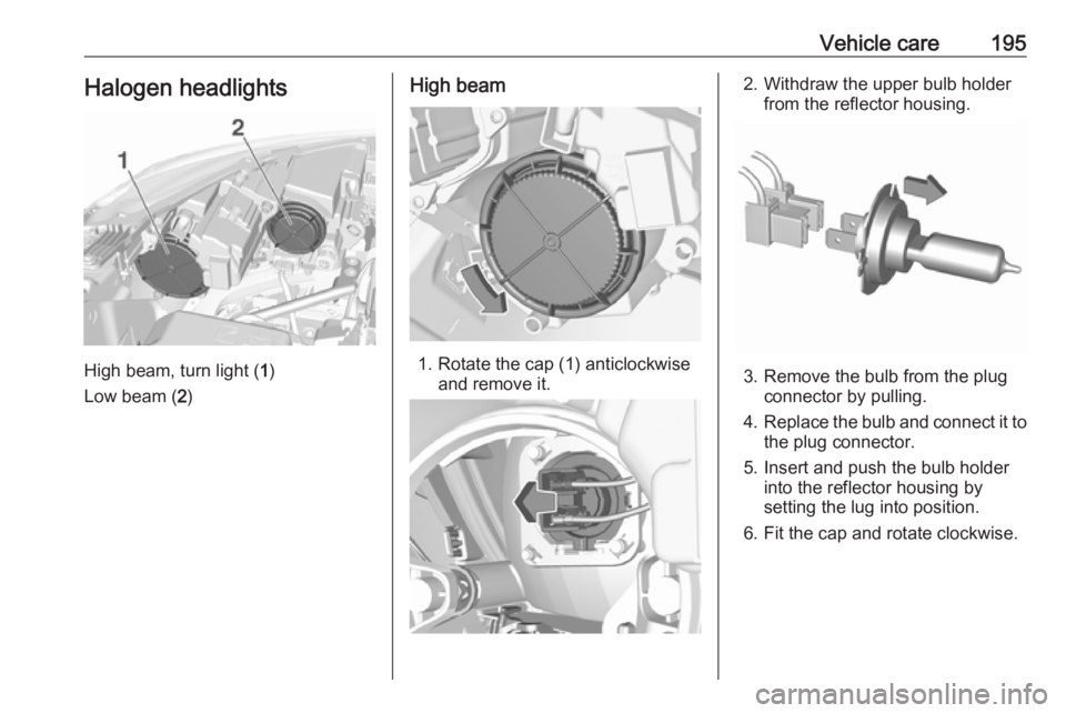
Vehicle care195Halogen headlights
High beam, turn light (1)
Low beam ( 2)
High beam
1. Rotate the cap (1) anticlockwise
and remove it.
2. Withdraw the upper bulb holderfrom the reflector housing.
3. Remove the bulb from the plugconnector by pulling.
4. Replace the bulb and connect it to
the plug connector.
5. Insert and push the bulb holder into the reflector housing by
setting the lug into position.
6. Fit the cap and rotate clockwise.
Page 198 of 263
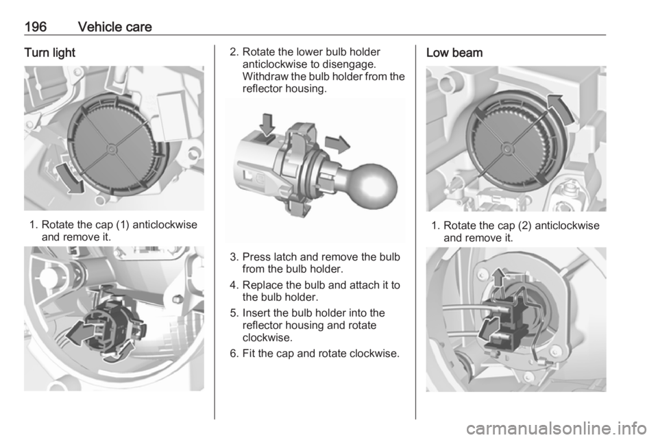
196Vehicle careTurn light
1. Rotate the cap (1) anticlockwiseand remove it.
2. Rotate the lower bulb holder anticlockwise to disengage.
Withdraw the bulb holder from the
reflector housing.
3. Press latch and remove the bulb from the bulb holder.
4. Replace the bulb and attach it to the bulb holder.
5. Insert the bulb holder into the reflector housing and rotate
clockwise.
6. Fit the cap and rotate clockwise.
Low beam
1. Rotate the cap (2) anticlockwise and remove it.
Page 199 of 263
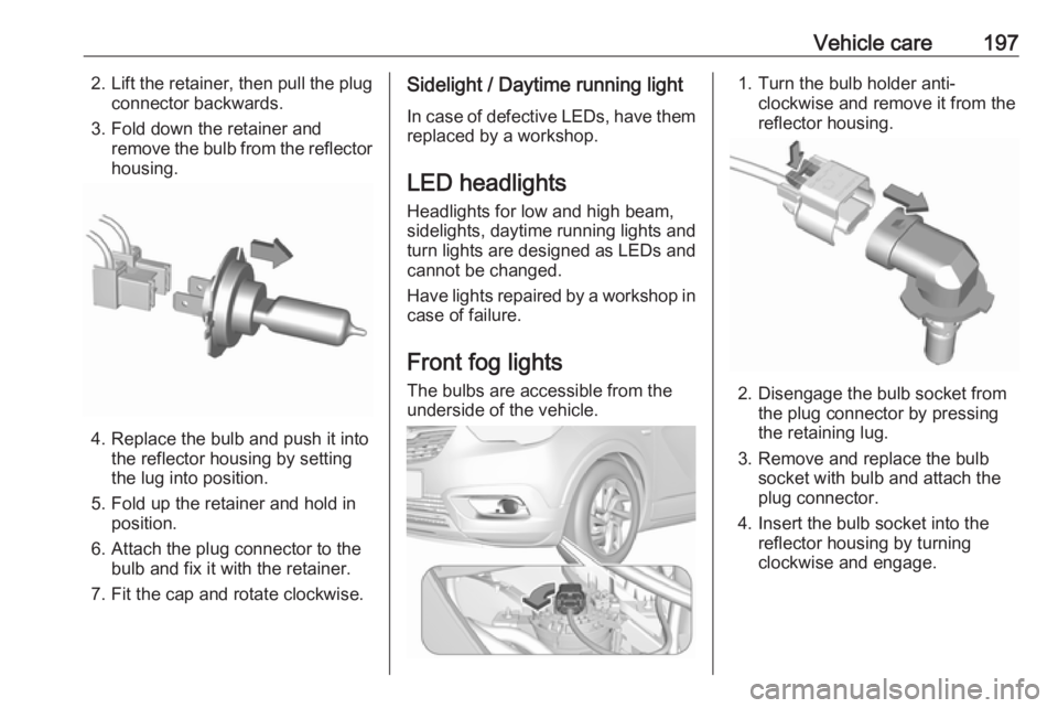
Vehicle care1972.Lift the retainer, then pull the plug
connector backwards.
3. Fold down the retainer and remove the bulb from the reflector
housing.
4. Replace the bulb and push it into the reflector housing by setting
the lug into position.
5. Fold up the retainer and hold in position.
6. Attach the plug connector to the bulb and fix it with the retainer.
7. Fit the cap and rotate clockwise.
Sidelight / Daytime running light
In case of defective LEDs, have them
replaced by a workshop.
LED headlights
Headlights for low and high beam,
sidelights, daytime running lights and turn lights are designed as LEDs and
cannot be changed.
Have lights repaired by a workshop in
case of failure.
Front fog lights
The bulbs are accessible from the
underside of the vehicle.1. Turn the bulb holder anti- clockwise and remove it from the
reflector housing.
2. Disengage the bulb socket from the plug connector by pressing
the retaining lug.
3. Remove and replace the bulb socket with bulb and attach the
plug connector.
4. Insert the bulb socket into the reflector housing by turning
clockwise and engage.
Page 200 of 263
198Vehicle careTail lightsDepending on version, tail lights and
brake lights are designed as LEDs. In case of failure, have LEDs replaced
by a workshop.
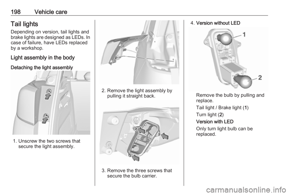
Light assembly in the body
Detaching the light assembly
1. Unscrew the two screws that secure the light assembly.
2. Remove the light assembly bypulling it straight back.
3. Remove the three screws that secure the bulb carrier.
4.Version without LED
Remove the bulb by pulling and
replace.
Tail light / Brake light ( 1)
Turn light ( 2)
Version with LED
Only turn light bulb can be
replaced.
Page 201 of 263
Vehicle care199
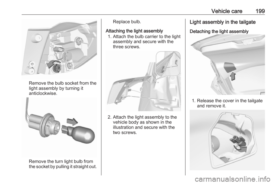
Remove the bulb socket from thelight assembly by turning it
anticlockwise.
Remove the turn light bulb from
the socket by pulling it straight out.
Replace bulb.
Attaching the light assembly 1. Attach the bulb carrier to the light assembly and secure with the
three screws.
2. Attach the light assembly to the vehicle body as shown in the
illustration and secure with the
two screws.
Light assembly in the tailgate
Detaching the light assembly
1. Release the cover in the tailgate and remove it.