remove OPEL CROSSLAND X 2019 Manual user
[x] Cancel search | Manufacturer: OPEL, Model Year: 2019, Model line: CROSSLAND X, Model: OPEL CROSSLAND X 2019Pages: 263, PDF Size: 8.11 MB
Page 69 of 263
Storage67The armrest can also be folded down
from the rear by pulling the loop.
Suitable for loading long, narrow
objects.
Ensure that the armrest engages
after folding up.
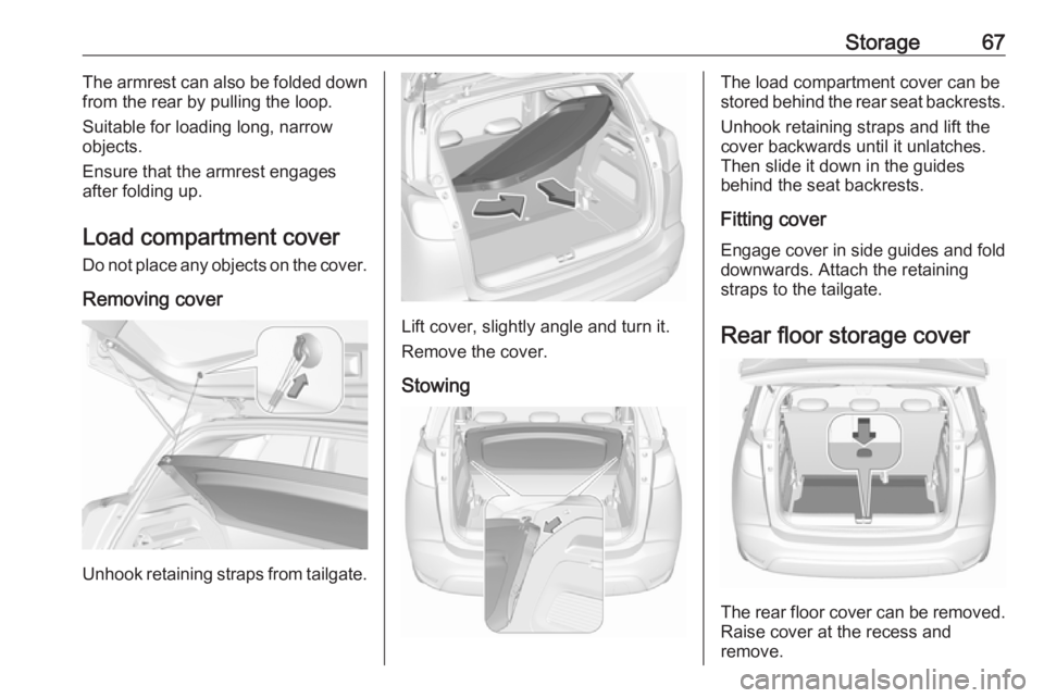
Load compartment cover Do not place any objects on the cover.
Removing cover
Unhook retaining straps from tailgate.
Lift cover, slightly angle and turn it.
Remove the cover.
Stowing
The load compartment cover can be
stored behind the rear seat backrests.
Unhook retaining straps and lift the
cover backwards until it unlatches.
Then slide it down in the guides
behind the seat backrests.
Fitting cover Engage cover in side guides and fold downwards. Attach the retainingstraps to the tailgate.
Rear floor storage cover
The rear floor cover can be removed.
Raise cover at the recess and
remove.
Page 70 of 263
68StorageThe cover can also be stored behind
the rear seats.
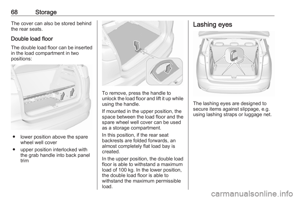
Double load floor
The double load floor can be inserted
in the load compartment in two
positions:
● lower position above the spare wheel well cover
● upper position interlocked with the grab handle into back panel
trim
To remove, press the handle to
unlock the load floor and lift it up while
using the handle.
If mounted in the upper position, the
space between the load floor and the spare wheel well cover can be used
as a storage compartment.
In this position, if the rear seat
backrests are folded forwards, an
almost completely flat load bay is
created.
In the upper position, the double load
floor is able to withstand a maximum
load of 100 kg. In the lower position,
the double load floor is able to
withstand the maximum permissible
load.
Lashing eyes
The lashing eyes are designed to
secure items against slippage, e.g.
using lashing straps or luggage net.
Page 72 of 263
70StorageRoof rack systemRoof rackFor safety reasons and to avoid
damage to the roof, the vehicle-
approved roof rack system is
recommended.
Follow the installation instructions and remove the roof rack when not in
use.
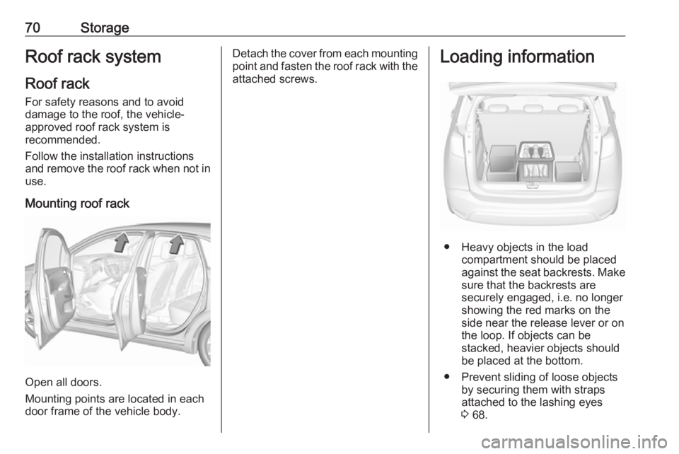
Mounting roof rack
Open all doors.
Mounting points are located in each
door frame of the vehicle body.
Detach the cover from each mounting
point and fasten the roof rack with the attached screws.Loading information
● Heavy objects in the load compartment should be placed
against the seat backrests. Make
sure that the backrests are
securely engaged, i.e. no longer
showing the red marks on the side near the release lever or on
the loop. If objects can be
stacked, heavier objects should
be placed at the bottom.
● Prevent sliding of loose objects by securing them with straps
attached to the lashing eyes
3 68.
Page 80 of 263
78Instruments and controlsNote
The sockets must always be kept
clean and dry.
Inductive charging9 Warning
Inductive charging can affect the
operation of implanted
pacemakers or other medical
devices. If applicable, seek
medical advice before using the
inductive charging device.
9 Warning
Remove any metal objects from
the charging device before
charging a mobile device, as these objects could become very hot.
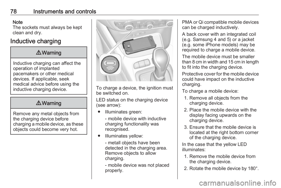
To charge a device, the ignition must
be switched on.
LED status on the charging device (see arrow):
● Illuminates green: - mobile device with inductivecharging functionality was
recognised.
● Illuminates yellow: - metall objects have been
detected in the charging area.
Remove objects to allow
charging.
- mobile device was not placed
properly.
PMA or Qi compatible mobile devices can be charged inductively.
A back cover with an integrated coil (e.g. Samsung 4 and 5) or a jacket
(e.g. some iPhone models) may be
required to charge a mobile device.
The mobile device must be smaller
than 8 cm in width and 15 cm in length
to fit into the charging device.
Protective cover for the mobile device could have impact on the inductive
charging.
To charge a mobile device: 1. Remove all objects from the charging device.
2. Place the mobile device with the display facing upwards on the
charging device.
3. Ensure that the mobile device is located at the right bottom corner
of the charging device.
In the case that the yellow LED
illuminates:
1. Remove the mobile device from the charging device.
2. Rotate the mobile device by 180°.
Page 95 of 263
Instruments and controls93Flashes yellowThe remaining driving range is
between 0 and 600 km.
AdBlue level is low. Refill AdBlue
soon to avoid prevention of the
engine start. Up to 10 l of AdBlue can
be added.
AdBlue 3 141.
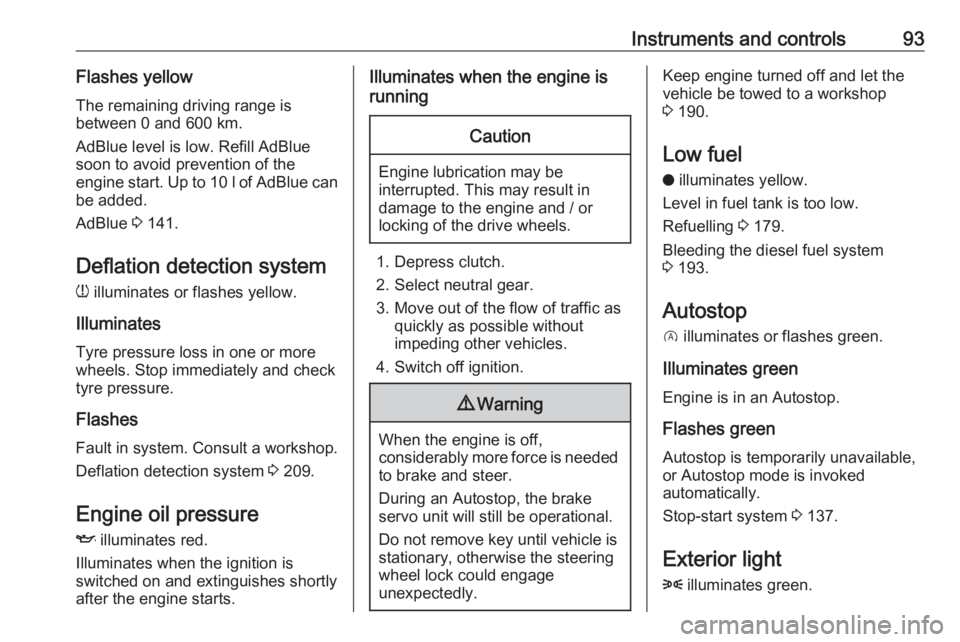
Deflation detection system w illuminates or flashes yellow.
Illuminates Tyre pressure loss in one or more
wheels. Stop immediately and check
tyre pressure.
Flashes
Fault in system. Consult a workshop.
Deflation detection system 3 209.
Engine oil pressure
I illuminates red.
Illuminates when the ignition is
switched on and extinguishes shortly
after the engine starts.Illuminates when the engine is
runningCaution
Engine lubrication may be
interrupted. This may result in
damage to the engine and / or
locking of the drive wheels.
1. Depress clutch.
2. Select neutral gear.
3. Move out of the flow of traffic as quickly as possible without
impeding other vehicles.
4. Switch off ignition.
9 Warning
When the engine is off,
considerably more force is needed
to brake and steer.
During an Autostop, the brake
servo unit will still be operational.
Do not remove key until vehicle is stationary, otherwise the steeringwheel lock could engage
unexpectedly.
Keep engine turned off and let the
vehicle be towed to a workshop
3 190.
Low fuel o illuminates yellow.
Level in fuel tank is too low.
Refuelling 3 179.
Bleeding the diesel fuel system
3 193.
Autostop D illuminates or flashes green.
Illuminates green
Engine is in an Autostop.
Flashes green
Autostop is temporarily unavailable,
or Autostop mode is invoked
automatically.
Stop-start system 3 137.
Exterior light 8 illuminates green.
Page 119 of 263
Lighting117
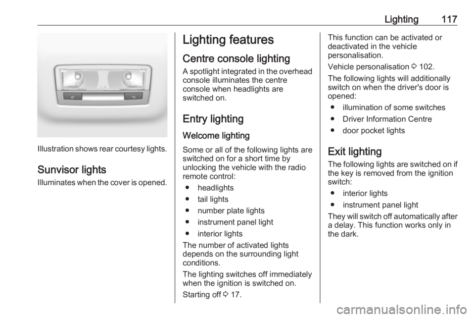
Illustration shows rear courtesy lights.
Sunvisor lights Illuminates when the cover is opened.
Lighting features
Centre console lighting A spotlight integrated in the overheadconsole illuminates the centre
console when headlights are
switched on.
Entry lighting
Welcome lighting Some or all of the following lights are
switched on for a short time by
unlocking the vehicle with the radio
remote control:
● headlights
● tail lights
● number plate lights
● instrument panel light
● interior lights
The number of activated lights
depends on the surrounding light
conditions.
The lighting switches off immediately
when the ignition is switched on.
Starting off 3 17.This function can be activated or
deactivated in the vehicle
personalisation.
Vehicle personalisation 3 102.
The following lights will additionally
switch on when the driver's door is
opened:
● illumination of some switches
● Driver Information Centre
● door pocket lights
Exit lighting The following lights are switched on if
the key is removed from the ignition
switch:
● interior lights
● instrument panel light
They will switch off automatically after
a delay. This function works only in
the dark.
Page 131 of 263
Climate control129Fixed air ventsAdditional air vents are located
beneath the windscreen and door windows and in the foot wells.Maintenance
Air intake
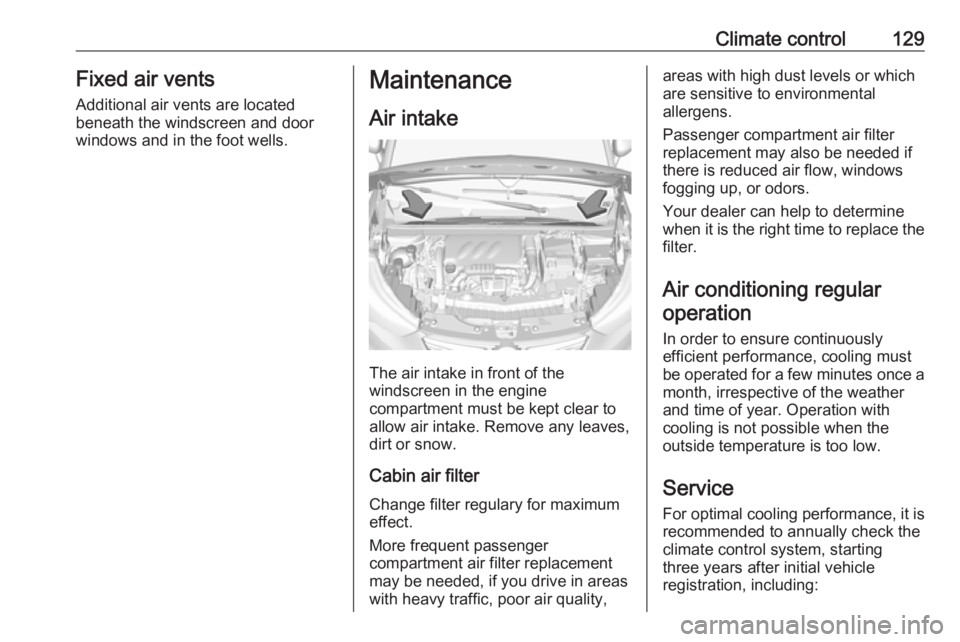
The air intake in front of the
windscreen in the engine
compartment must be kept clear to
allow air intake. Remove any leaves,
dirt or snow.
Cabin air filter
Change filter regulary for maximum
effect.
More frequent passenger
compartment air filter replacement
may be needed, if you drive in areas
with heavy traffic, poor air quality,
areas with high dust levels or which
are sensitive to environmental
allergens.
Passenger compartment air filter
replacement may also be needed if
there is reduced air flow, windows
fogging up, or odors.
Your dealer can help to determine
when it is the right time to replace the
filter.
Air conditioning regularoperation
In order to ensure continuously
efficient performance, cooling must
be operated for a few minutes once a month, irrespective of the weather
and time of year. Operation with
cooling is not possible when the
outside temperature is too low.
Service For optimal cooling performance, it is
recommended to annually check the
climate control system, starting
three years after initial vehicle
registration, including:
Page 135 of 263
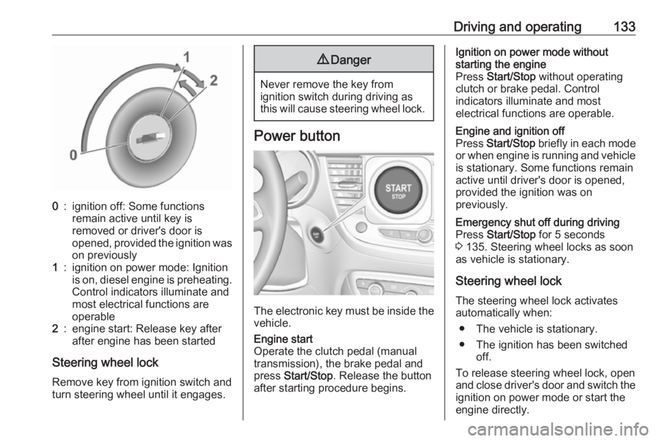
Driving and operating1330:ignition off: Some functions
remain active until key is
removed or driver's door is
opened, provided the ignition was
on previously1:ignition on power mode: Ignition
is on, diesel engine is preheating. Control indicators illuminate and
most electrical functions are
operable2:engine start: Release key after
after engine has been started
Steering wheel lock
Remove key from ignition switch and
turn steering wheel until it engages.
9 Danger
Never remove the key from
ignition switch during driving as
this will cause steering wheel lock.
Power button
The electronic key must be inside the
vehicle.
Engine start
Operate the clutch pedal (manual
transmission), the brake pedal and
press Start/Stop . Release the button
after starting procedure begins.Ignition on power mode without
starting the engine
Press Start/Stop without operating
clutch or brake pedal. Control
indicators illuminate and most
electrical functions are operable.Engine and ignition off
Press Start/Stop briefly in each mode
or when engine is running and vehicle
is stationary. Some functions remain
active until driver's door is opened,
provided the ignition was on
previously.Emergency shut off during driving
Press Start/Stop for 5 seconds
3 135. Steering wheel locks as soon
as vehicle is stationary.
Steering wheel lock
The steering wheel lock activates
automatically when:
● The vehicle is stationary.
● The ignition has been switched off.
To release steering wheel lock, open
and close driver's door and switch the ignition on power mode or start the
engine directly.
Page 141 of 263
Driving and operating139Parking9Warning
● Do not park the vehicle on an
easily ignitable surface. The
high temperature of the
exhaust system could ignite the
surface.
● Always apply the parking brake. Activate the manual
parking brake without pressing the release button. Apply as
firmly as possible on a downhill slope or uphill slope. Depress
brake pedal at the same time to
reduce operating force.
● Switch off the engine.
● If the vehicle is on a level surface or uphill slope, engage
first gear or set the selector
lever to position P before
removing the ignition key or
switching off ignition on
vehicles with power button. On an uphill slope, turn the front
wheels away from the kerb.
If the vehicle is on a downhill
slope, engage reverse gear or
set the selector lever to position
P before removing the ignition
key or switching off ignition on
vehicles with power button.
Turn the front wheels towards
the kerb.
● Close the windows.
● Remove the ignition key from the ignition switch or switch off
ignition on vehicles with power
button. Turn the steering wheel until the steering wheel lock is
felt to engage.
● Lock the vehicle.
● Activate the anti-theft alarm system.
● The engine cooling fans may run
after the engine has been
switched off 3 189.
Caution
After running at high engine
speeds or with high engine loads,
operate the engine briefly at a low
load or run in neutral for
approx. 30 seconds before
switching off, in order to protect
the turbocharger.
Note
In the event of an accident with
airbag deployment, the engine is
switched off automatically if the
vehicle comes to a standstill within a
certain time.
Page 145 of 263
Driving and operating143Note
When unscrewing the protective cap
from the filler neck, ammonia fumes may emerge. Do not inhale as the
fumes have a pungent smell. The
fumes are not harmful by inhalation.
It is recommended to fill the AdBlue
tank completely.
The vehicle must be parked on a level surface.
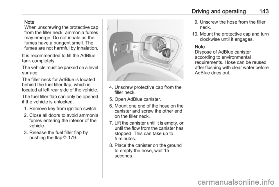
The filler neck for AdBlue is located
behind the fuel filler flap, which is located at left rear side of the vehicle.
The fuel filler flap can only be opened
if the vehicle is unlocked.
1. Remove key from ignition switch.
2. Close all doors to avoid ammonia fumes entering the interior of the
vehicle.
3. Release the fuel filler flap by pushing the flap 3 179.
4. Unscrew protective cap from the
filler neck.
5. Open AdBlue canister.
6. Mount one end of the hose on the
canister and screw the other end
on the filler neck.
7. Lift the canister until it is empty, or
until the flow from the canister has
stopped. This can take up to
5 minutes.
8. Place the canister on the ground to empty the hose, wait 15
seconds.
9. Unscrew the hose from the filler neck.
10. Mount the protective cap and turn
clockwise until it engages.
Note
Dispose of AdBlue canister
according to environmental
requirements. Hose can be reused
after flushing with clear water before AdBlue dries out.