engine OPEL FRONTERA 1998 Workshop Manual
[x] Cancel search | Manufacturer: OPEL, Model Year: 1998, Model line: FRONTERA, Model: OPEL FRONTERA 1998Pages: 6000, PDF Size: 97 MB
Page 2323 of 6000

MANUAL TRANSMISSION7B–5
Manual Transmission Assembly
Transmission and Associated Parts
220RW108
Legend
(1) Gear Control Lever and Knob
(2) Transfer Control Lever and Knob
(3) Front Console Assembly
(4) Grommet Assembly
(5) Transfer Protector
(6) Rear Propeller Shaft
(7) Front Propeller Shaft
(8) Exhaust Pipe
(9) Backup Lamp, 4WD Indicator, and 1–2
Indicator Switch Harness Connector
(10) Speedometer Sensor and 2WD–4WD Actuator
Harness Connector(11) Slave Cylinder Heat Protector
(12) Harness Heat Protector
(13) Slave Cylinder
(14) Dust Cover
(15) Engine Rear Mount Nut
(16) Engine Rear Mount Bolt
(17) Engine Rear Mount
(18) Third Crossmember
(19) Flywheel Under Cover
(20) Transmission Retaining Bolt
(21) Transmission Assembly with Transfer Case
Page 2324 of 6000

7B–6MANUAL TRANSMISSION
Removal
NOTE: Before remove the transmission and transfer
assembly from the vehicle, change the transfer mode to
2WD using push button on dash panel.
1. Remove engine hood.
2. Disconnect battery ground cable.
3. Remove the gear control lever knob.
4. Remove the front console assembly.
5. Remove the grommet assembly.
6. Remove the transmission control lever and transfer
control lever.
235RW014
7. Raise and support the vehicle with suitable jack
stand.
8. Remove transfer protector.
9. Remove the rear propeller shaft.
NOTE: Apply alignment marks on the flange at the both
front and rear side.
(4JX1)
401RW060
10. Remove the front propeller shaft.
NOTE: Apply alignment marks on the flange at both the
front and rear sides.
401RS003
11. Disconnect two oxygen sensor connectors from the
transmission harness (6VE1).
12.Remove the front and 3 way exhaust pipe (6VE1).
Remove the exhaust pipe with catalytic converter
(4JX1).
(4JX1)
150RW041
Page 2327 of 6000

MANUAL TRANSMISSION7B–9
16. Remove the slave cylinder heat protector.
17. Remove the harness heat protector (6VE1).
(6VE1)
225RW006
18. Remove two transmission harness clamps and
bracket (6VE1).
19. Remove the slave cylinder.
206RW002
20. Remove the two dust cover from transmission case.
21. Support the transfer case with a jack.22. Remove two engine rear mount nuts.
(6VE1)
022RT002
23. Remove third crossmember (6VE1).
24. Remove third crossmember with rear mount rubber
(4JX1).
(4JX1)
022RW013
25. Remove two engine rear mount bolts (6VE1).
26. Remove the rear mount from the transmission
(6VE1).
27. Remove three flywheel under cover (6VE1).
Page 2329 of 6000

MANUAL TRANSMISSION7B–11
220RW119
Legend
(1) Pressure Plate Assembly
(2) Release Bearing
(3) Wedge Collar
30. Remove the transmission retaining nuts and bolts.
31. Remove the transmission assembly with transfer
case from the vehicle.
NOTE: Remove the transfer case from the transmission
assembly if the transmission disassembly required.
Refer to Transfer Case in Drive Line/Axle section.
Installation
1. Apply a thin coat of molybdenum disulfide grease to
the top gear shaft spline.
2. Slowly operate the transmission jack until the front of
transmission is aligned with the rear of the engine.
The slope of the engine and the transmission must be
the same.
3. Align the top gear shaft spline with the clutch driven
plate spline.
220RS005
4. Install the transmission to the engine.
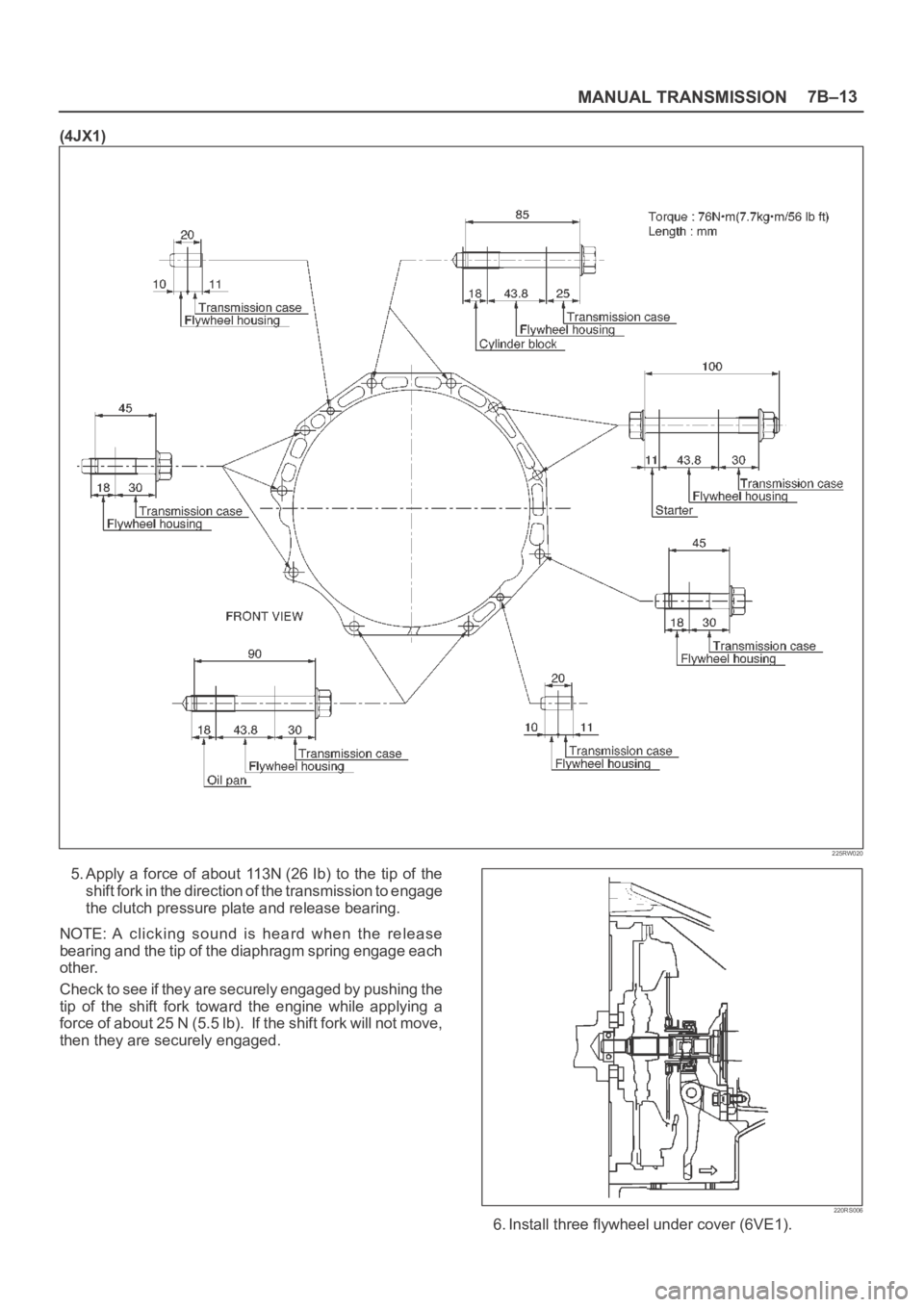
Tighten the transmission retaining nuts and bolts.
Page 2331 of 6000

MANUAL TRANSMISSION7B–13
(4JX1)
225RW020
5. Apply a force of about 113N (26 Ib) to the tip of the
shift fork in the direction of the transmission to engage
the clutch pressure plate and release bearing.
NOTE: A clicking sound is heard when the release
bearing and the tip of the diaphragm spring engage each
other.
Check to see if they are securely engaged by pushing the
tip of the shift fork toward the engine while applying a
force of about 25 N (5.5 lb). If the shift fork will not move,
then they are securely engaged.
220RS006
6. Install three flywheel under cover (6VE1).
Page 2332 of 6000

7B–14MANUAL TRANSMISSION
7. Install the engine rear mount to the transmission case
and tighten the fixing bolts specified torque (6VE1).
Torque: 41 Nꞏm (4.2kgꞏm/30 Ib ft)
8. Install the third crossmember to the frame and tighten
the fixing bolts specified torque.
Torque: 50 Nꞏm (5.1kgꞏm/37 Ib ft)
9. Tighten the engine rear mount nuts specified torque.
Torque: 50 Nꞏm (5.1kgꞏm/37 Ib ft)
10. Remove the transmission jack.
11. Apply the grease to top hole portion of the shift fork.
12. Install the slave cylinder and tighten the fixing bolts
specified torque.
Torque: 43 Nꞏm (4.4kgꞏm/32 Ib ft)
13. Install the clutch dust cover to the clutch housing and
tighten the fixing bolts specified torque.
Torque: 8 Nꞏm (0.8kgꞏm/69 Ib in)
220RS007
14. Install the slave cylinder heat protector to the slave
cylinder.
15. Install bracket and two transmission harness clamps
to the transmission case (6VE1).
16. Install harness heat protector (6VE1).(6VE1)
225RW006
17. Install four fuel pipe bracket (6VE1).
Page 2334 of 6000

7B–16MANUAL TRANSMISSION
19. Connect the backup lamp switch, 4WD indicator
switch, and 1-2 indicator switch harness connectors.
826RW023
20. Install the front and 3 way exhaust pipe (6VE1).
Install the exhaust pipe with catalytic converter
(4JX1).
Torque:
Exhaust pipe to exhaust manifold:
67 Nꞏm (6.8 kgꞏm/49 Ib ft)
Exhaust pipe flange bolt:
43 Nꞏm (4.4 kgꞏm/32 Ib ft)
(4JX1)
150RW041
21. Connect two oxygen sensor connectors to the
transmission harness (6VE1).
22. Install the front propeller shaft and tighten the fixing
bolts and nuts specified torque.
Torque: 63 Nꞏm (6.4 kgꞏm/46 Ib ft)
23. Install the rear propeller shaft and tighten the fixing
bolts and nuts specified torque.
Torque: 63 Nꞏm (6.4 kgꞏm/46 Ib ft)24. Install transfer protector and tighten the fixing bolts
specified torque.
Torque: 37 Nꞏm (3.8 kgꞏm/27 Ib ft)
25. Install the transmission control lever and transfer
control lever.
235RW014
26. Install the grommet assembly.
27. Install the front console assembly.
28. Install the gear control lever knob.
29. Connect battery ground cable.
30. Install engine hood.
Page 2360 of 6000

7B–42MANUAL TRANSMISSION
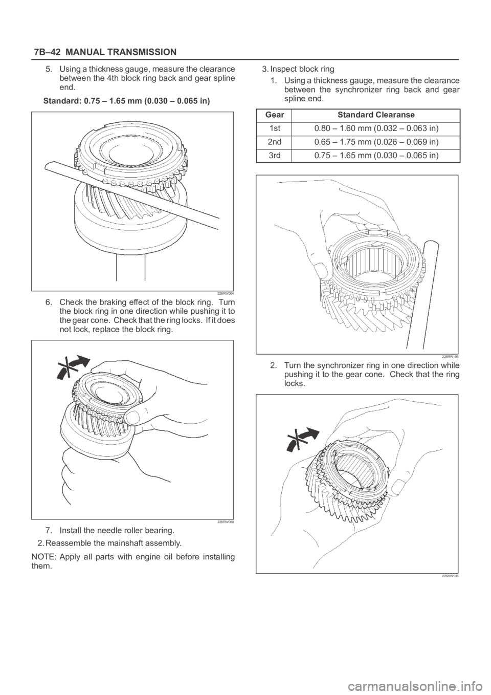
5. Using a thickness gauge, measure the clearance
between the 4th block ring back and gear spline
end.
Standard: 0.75 – 1.65 mm (0.030 – 0.065 in)
226RW064
6. Check the braking effect of the block ring. Turn
the block ring in one direction while pushing it to
the gear cone. Check that the ring locks. If it does
not lock, replace the block ring.
226RW060
7. Install the needle roller bearing.
2. Reassemble the mainshaft assembly.
NOTE: Apply all parts with engine oil before installing
them.3. Inspect block ring
1. Using a thickness gauge, measure the clearance
between the synchronizer ring back and gear
spline end.
Gear
Standard Clearanse
1st0.80–1.60mm (0.032–0.063in)
2nd0.65–1.75mm (0.026–0.069in)
3rd0.75–1.65mm (0.030–0.065in)
226RW105
2. Turn the synchronizer ring in one direction while
pushing it to the gear cone. Check that the ring
locks.
226RW106
Page 2386 of 6000

7B–68MANUAL TRANSMISSION
Main Data and Specifications
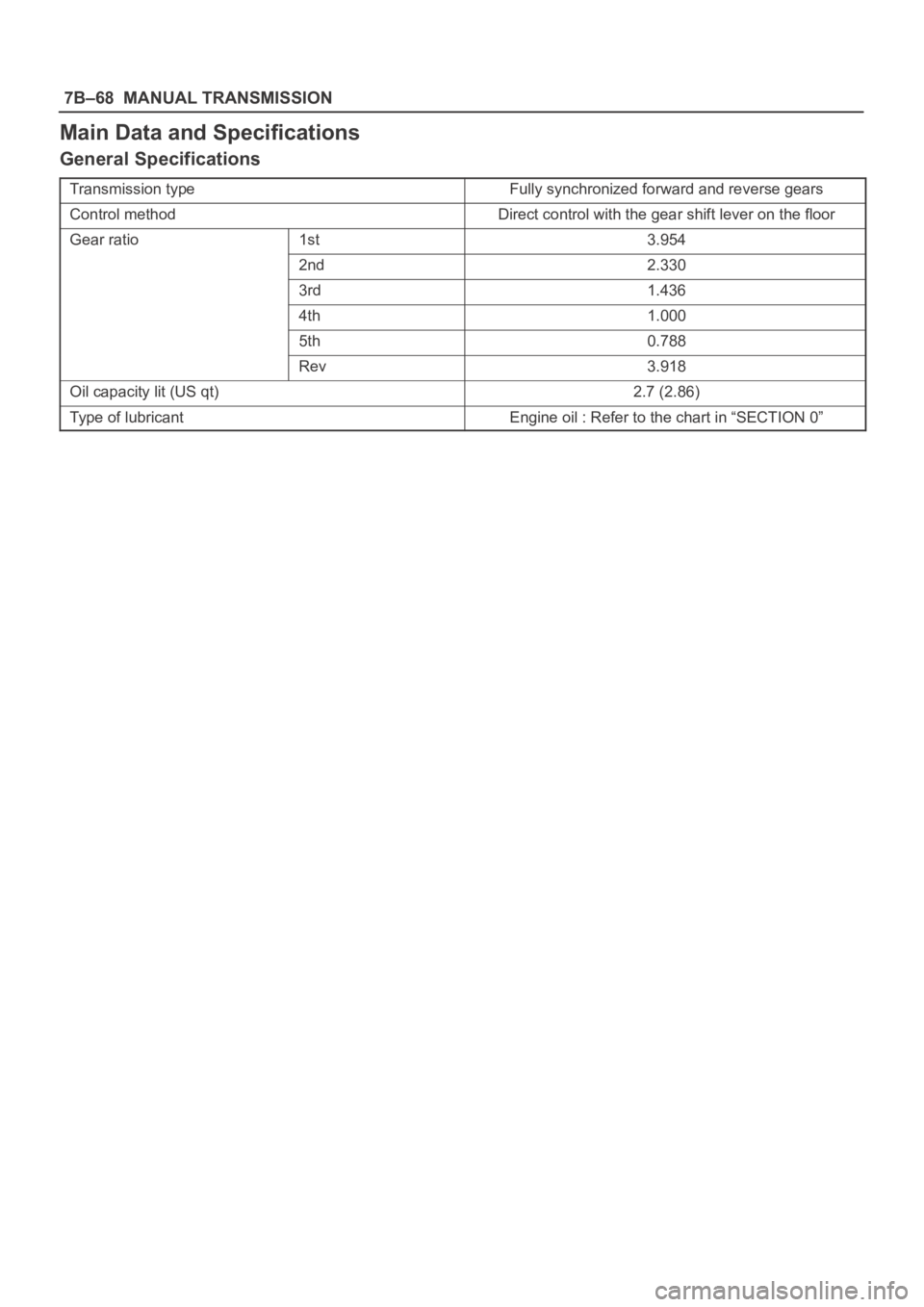
General Specifications
Transmission typeFully synchronized forward and reverse gears
Control methodDirect control with the gear shift lever on the floor
Gear ratio1st3.954
2nd2.330
3rd1.436
4th1.000
5th0.788
Rev3.918
Oil capacity lit (US qt)2.7 (2.86)
Type of lubricantEngine oil : Refer to the chart in “SECTION 0”
Page 2517 of 6000

7C–8CLUTCH
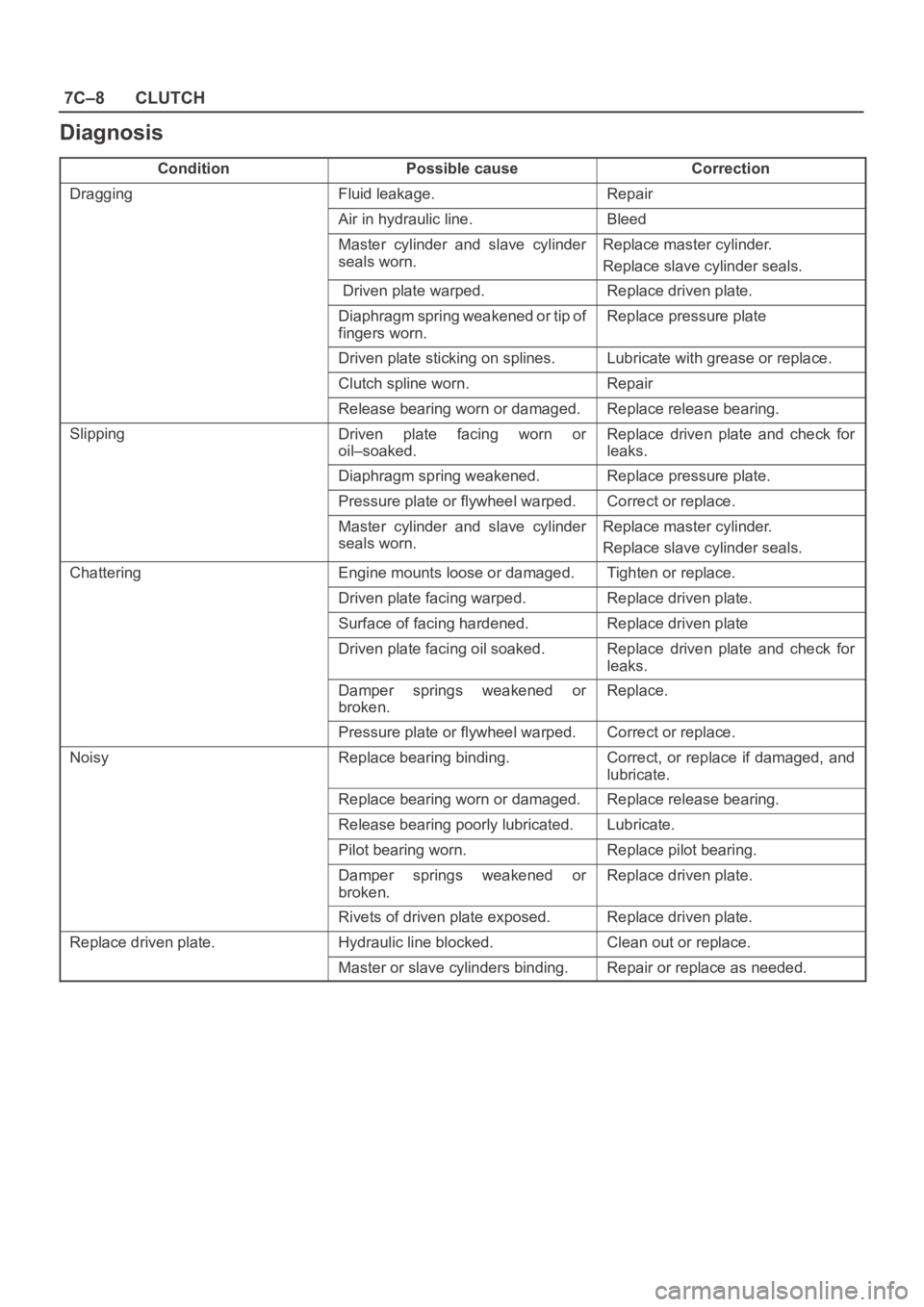
Diagnosis
ConditionPossible causeCorrection
DraggingFluid leakage.Repair
Air in hydraulic line.Bleed
Master cylinder and slave cylinder
seals worn. Replace master cylinder.
Replace slave cylinder seals.
Driven plate warped.Replace driven plate.
Diaphragm spring weakened or tip of
fingers worn. Replace pressure plate
Driven plate sticking on splines.Lubricate with grease or replace.
Clutch spline worn. Repair
Release bearing worn or damaged.Replace release bearing.
SlippingDriven plate facing worn or
oil–soaked.Replace driven plate and check for
leaks.
Diaphragm spring weakened.Replace pressure plate.
Pressure plate or flywheel warped.Correct or replace.
Master cylinder and slave cylinder
seals worn.Replace master cylinder.
Replace slave cylinder seals.
ChatteringEngine mounts loose or damaged.Tighten or replace.
Driven plate facing warped.Replace driven plate.
Surface of facing hardened.Replace driven plate
Driven plate facing oil soaked. Replace driven plate and check for
leaks.
Damper springs weakened or
broken. Replace.
Pressure plate or flywheel warped.Correct or replace.
NoisyReplace bearing binding.Correct, or replace if damaged, and
lubricate.
Replace bearing worn or damaged. Replace release bearing.
Release bearing poorly lubricated. Lubricate.
Pilot bearing worn.Replace pilot bearing.
Damper springs weakened or
broken.Replace driven plate.
Rivets of driven plate exposed.Replace driven plate.
Replace driven plate.Hydraulic line blocked.Clean out or replace.
Master or slave cylinders binding.Repair or replace as needed.