fuse diagram OPEL FRONTERA 1998 Workshop Manual
[x] Cancel search | Manufacturer: OPEL, Model Year: 1998, Model line: FRONTERA, Model: OPEL FRONTERA 1998Pages: 6000, PDF Size: 97 MB
Page 1118 of 6000
6E–1 ENGINE DRIVEABILITY AND EMISSIONS
ENGINE
ENGINE DRIVEABILITY AND EMISSIONS
CONTENTS
Specifications 6E–5. . . . . . . . . . . . . . . . . . . . . . . . .
Tightening Specifications 6E–5. . . . . . . . . . . . . . .
Vehicle Type Specifications 6E–5. . . . . . . . . . . . .
Diagrams and Schematics 6E–6. . . . . . . . . . . . . . . .
PCM Wiring Diagram (1 of 11) 6E–6. . . . . . . . . . .
PCM Wiring Diagram (2 of 11) For EC,
THAILAND, SOUTH EAST ASIA, LATIN
AMERICA, GULF, SAUDI, CHINA. 6E–7. . . . . .
PCM Wiring Diagram (3 of 11) For SOUTH
AFRICA and EXP. 6E–8. . . . . . . . . . . . . . . . . . . . .
PCM Wiring Diagram (4 of 11) 6E–9. . . . . . . . . . .
PCM Wiring Diagram (5 of 11) 6E–10. . . . . . . . . . .
PCM Wiring Diagram (6 of 11) For
AUSTRALIA, THAILAND, SOUTH EAST
ASIA, LATIN AMERICA, GULF, SAUDI,
LATIN AMERICA. 6E–11. . . . . . . . . . . . . . . . . . . . .
PCM Wiring Diagram (7 of 11) For EC. 6E–12. . .
PCM Wiring Diagram (8 of 11) For EXPORT
and SOUTH AFRICA. 6E–13. . . . . . . . . . . . . . . . .
PCM Wiring Diagram (9 of 11) Except EXP
and SOUTH AFRICA 6E–14. . . . . . . . . . . . . . . . . .
PCM Wiring Diagram (10 of 11) For
EXPORT and SOUTH AFRICA 6E–15. . . . . . . . .
PCM Wiring Diagram (11 of 11) 6E–16. . . . . . . . . .
PCM Pinouts 6E–17. . . . . . . . . . . . . . . . . . . . . . . . . . .
PCM Pinout Table, 32-Way Red
Connector – Row “A” 6E–17. . . . . . . . . . . . . . . . . .
PCM Pinout Table, 32-Way Red
Connector – Row “B” 6E–19. . . . . . . . . . . . . . . . . .
PCM Pinout Table, 32-Way White
Connector – Row “C” (For EC) 6E–20. . . . . . . . . .
PCM Pinout Table, 32-Way White
Connector – Row “C” (For except EC) 6E–21. . .
PCM Pinout Table, 32-Way White
Connector – Row “D”
(For except EXPORT and SOUTH
AFRICA) 6E–22. . . . . . . . . . . . . . . . . . . . . . . . . . . . .
PCM Pinout Table, 32-Way White
Connector – Row “D”
(For EXPORT and SOUTH AFRICA) 6E–23. . . . .
PCM Pinout Table, 32-Way Blue
Connector – Row “E”
(For except EXPORT and SOUTH
AFRICA) 6E–24. . . . . . . . . . . . . . . . . . . . . . . . . . . . .
PCM Pinout Table, 32-Way Blue
Connector – Row “E”
(For EXPORT and SOUTH AFRICA) 6E–26. . . . .
PCM Pinout Table, 32-Way Blue
Connector – Row “F” 6E–27. . . . . . . . . . . . . . . . . .
Component Locators 6E–28. . . . . . . . . . . . . . . . . . . .
Engine Component Locator (This illustration
is based on RHD model.) 6E–28. . . . . . . . . . . . . . Engine Component Locator Table 6E–29. . . . . . . .
Engine Component Locator Table 6E–31. . . . . . . .
Undercarriage Component Locator 6E–32. . . . . .
Undercarriage Component Locator Table
(Automatic Transmission) 6E–32. . . . . . . . . . . . . .
Undercarriage Component Locator Table
(Manual Transmission) 6E–33. . . . . . . . . . . . . . . .
Fuse and Relay Panel (Underhood
Electrical Center) 6E–33. . . . . . . . . . . . . . . . . . . . .
Sensors and Miscellaneous Component
Locators 6E–34. . . . . . . . . . . . . . . . . . . . . . . . . . . . .
Diagnosis 6E–37. . . . . . . . . . . . . . . . . . . . . . . . . . . . . .
Strategy-Based Diagnostics 6E–37. . . . . . . . . . . . .
Strategy-Based Diagnostics 6E–37. . . . . . . . . . . . .
DTC Stored 6E–37
. . . . . . . . . . . . . . . . . . . . . . . . . . .
No DTC 6E–37. . . . . . . . . . . . . . . . . . . . . . . . . . . . . .
No Matching Symptom 6E–37. . . . . . . . . . . . . . . . .
Intermittents 6E–37. . . . . . . . . . . . . . . . . . . . . . . . . .
No Trouble Found 6E–37. . . . . . . . . . . . . . . . . . . . .
Verifying Vehicle Repair 6E–37. . . . . . . . . . . . . . . .
General Service Information 6E–38. . . . . . . . . . . . . .
OBD Serviceablity Issues 6E–38. . . . . . . . . . . . . . .
Maintenance Schedule 6E–38. . . . . . . . . . . . . . . . .
Visual / Physical Engine Compartment
Inspection 6E–38. . . . . . . . . . . . . . . . . . . . . . . . . . . .
Basic Knowledge of Tools Required 6E–38. . . . . .
Serial Data Communications 6E–38. . . . . . . . . . . . . .
Class II Serial Data Communications 6E–38. . . . .
On-Board Diagnostic (OBD) 6E–39. . . . . . . . . . . . . .
On-Board Diagnostic Tests 6E–39. . . . . . . . . . . . .
Comprehensive Component Monitor
Diagnostic Operation 6E–39. . . . . . . . . . . . . . . . . .
Common OBD Terms 6E–40. . . . . . . . . . . . . . . . . .
The Diagnostic Executive 6E–40. . . . . . . . . . . . . . .
DTC Types 6E–41. . . . . . . . . . . . . . . . . . . . . . . . . . .
Verifying Vehicle Repair 6E–42. . . . . . . . . . . . . . . .
Reading Diagnostic Trouble Codes Using
A Tech 2 6E–42. . . . . . . . . . . . . . . . . . . . . . . . . . . . .
Tech 2 Tech 2 6E–43. . . . . . . . . . . . . . . . . . . . . . . . .
Tech 2 Features 6E–43. . . . . . . . . . . . . . . . . . . . . . .
Getting Started 6E–44. . . . . . . . . . . . . . . . . . . . . . . .
Operating Procedure (For Example) 6E–44. . . . .
DTC Modes 6E–45. . . . . . . . . . . . . . . . . . . . . . . . . . .
DTC Information Mode 6E–46. . . . . . . . . . . . . . . . .
Injector Balance Test 6E–46. . . . . . . . . . . . . . . . . . .
EGR Control Test 6E–47. . . . . . . . . . . . . . . . . . . . . .
Idle Air Control System Test 6E–48. . . . . . . . . . . . .
Page 1436 of 6000
6E–319 ENGINE DRIVEABILITY AND EMISSIONS
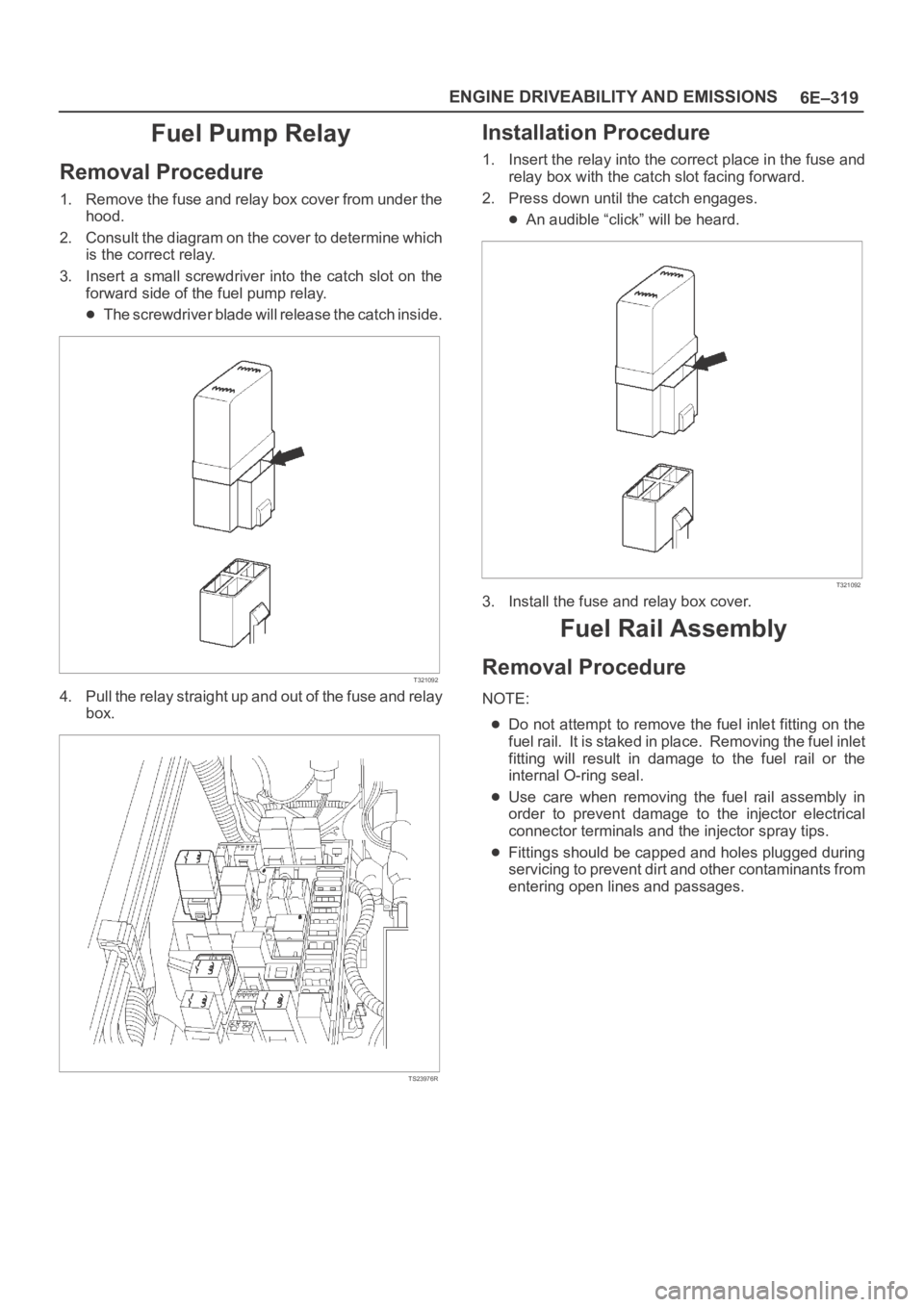
Fuel Pump Relay
Removal Procedure
1. Remove the fuse and relay box cover from under the
hood.
2. Consult the diagram on the cover to determine which
is the correct relay.
3. Insert a small screwdriver into the catch slot on the
forward side of the fuel pump relay.
The screwdriver blade will release the catch inside.
T321092
4. Pull the relay straight up and out of the fuse and relay
box.
TS23976R
Installation Procedure
1. Insert the relay into the correct place in the fuse and
relay box with the catch slot facing forward.
2. Press down until the catch engages.
An audible “click” will be heard.
T321092
3. Install the fuse and relay box cover.
Fuel Rail Assembly
Removal Procedure
NOTE:
Do not attempt to remove the fuel inlet fitting on the
fuel rail. It is staked in place. Removing the fuel inlet
fitting will result in damage to the fuel rail or the
internal O-ring seal.
Use care when removing the fuel rail assembly in
order to prevent damage to the injector electrical
connector terminals and the injector spray tips.
Fittings should be capped and holes plugged during
servicing to prevent dirt and other contaminants from
entering open lines and passages.
Page 1442 of 6000
6E–325 ENGINE DRIVEABILITY AND EMISSIONS
Spark Plug Gap Check
Check the gap of all spark plugs before installation.
Use a round wire feeler gauge to ensure an accurate
check.
Plugs installed with the wrong gap can cause poor
engine performance and excessive emissions.
Installation Procedure
NOTE: The plug must thread smoothly into the cylinder
head and be fully seated. Use a thread chaser if
necessary to clean the threads in the cylinder head.
Cross-threading or failure to fully seat the spark plug can
cause plug overheating, exhaust blow-by gas, or thread
damage. Do not overtighten the spark plugs. Over
tightening can cause aluminum threads to strip.
1. Install the spark plug in the engine. Use the
appropriate spark plug socket.
Tighten
Tighten the spark plug to 18 Nꞏm (13 lb ft.).
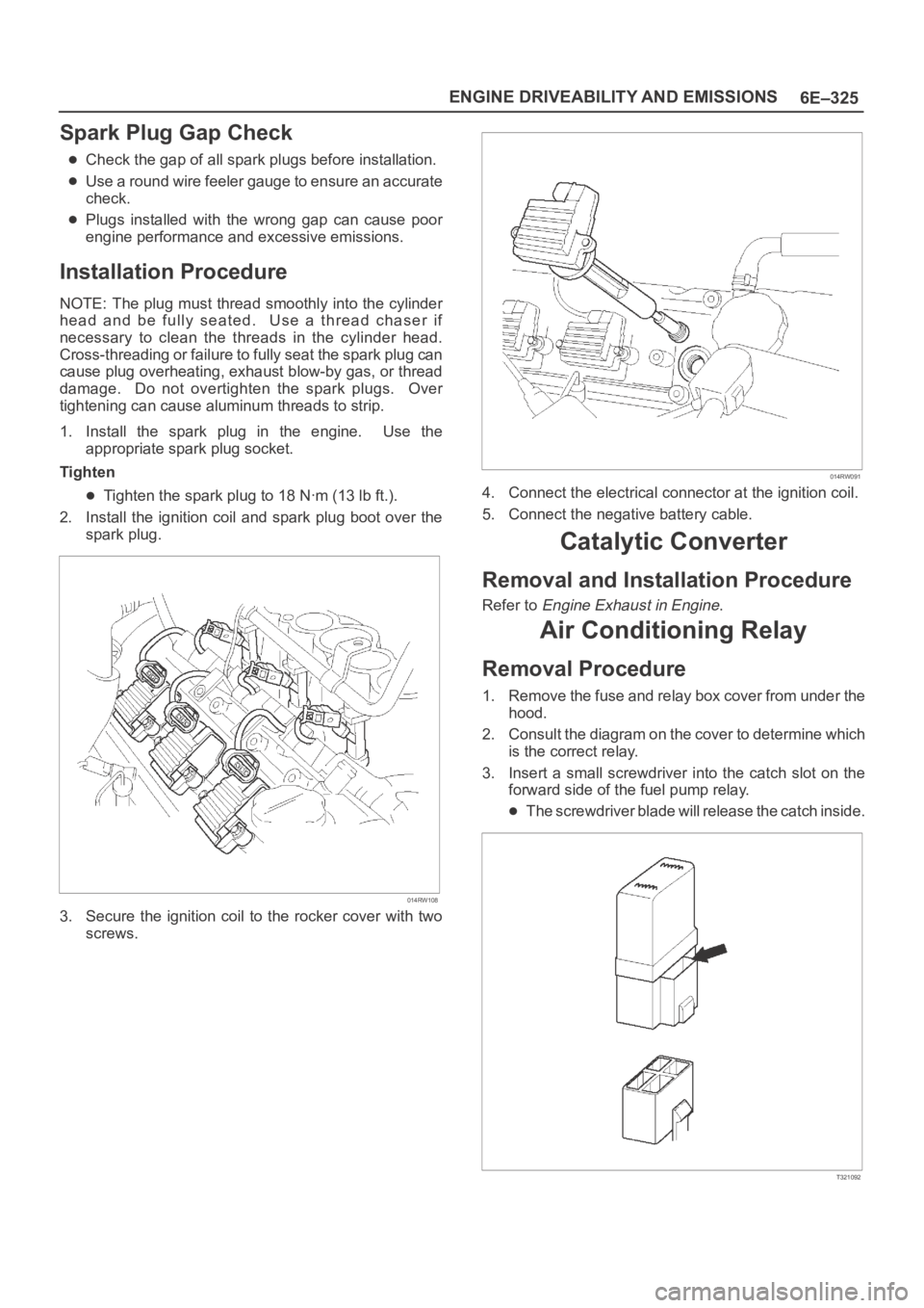
2. Install the ignition coil and spark plug boot over the
spark plug.
014RW108
3. Secure the ignition coil to the rocker cover with two
screws.
014RW091
4. Connect the electrical connector at the ignition coil.
5. Connect the negative battery cable.
Catalytic Converter
Removal and Installation Procedure
Refer to Engine Exhaust in Engine.
Air Conditioning Relay
Removal Procedure
1. Remove the fuse and relay box cover from under the
hood.
2. Consult the diagram on the cover to determine which
is the correct relay.
3. Insert a small screwdriver into the catch slot on the
forward side of the fuel pump relay.
The screwdriver blade will release the catch inside.
T321092
Page 1868 of 6000

ENGINE ELECTRICAL 6D – 1
ENGINE ELECTRICAL
CONTENTS
Battery . . . . . . . . . . . . . . . . . . . . . . . . . . . . 6D–1
General Description . . . . . . . . . . . . . . . . 6D–1
Diagnosis . . . . . . . . . . . . . . . . . . . . . . . . 6D–1
On Vehicle Service . . . . . . . . . . . . . . . . . 6D–3
Main Data and Specification . . . . . . . . . . 6D–4
Starting System . . . . . . . . . . . . . . . . . . . . . 6D–5
General Description . . . . . . . . . . . . . . . . 6D–5
On Vehicle Service . . . . . . . . . . . . . . . . . 6D–7
Starter . . . . . . . . . . . . . . . . . . . . . . . . . . 6D–7
Unit Repair . . . . . . . . . . . . . . . . . . . . . . . 6D–8Charging System . . . . . . . . . . . . . . . . . . . . 6D–15
General Description . . . . . . . . . . . . . . . . 6D–15
Diagnosis . . . . . . . . . . . . . . . . . . . . . . . . 6D–16
Unit Repair . . . . . . . . . . . . . . . . . . . . . . . 6D–17
Main Data and Specification . . . . . . . . . . 6D–22
QOS4 Preheating System . . . . . . . . . . . . . . 6D–23
General Description . . . . . . . . . . . . . . . . 6D–23
System Diagram . . . . . . . . . . . . . . . . . . . 6D–23
Inspection of QOS4 System Operation . . 6D–24
BATTERY
GENERAL DESCRIPTION
DIAGNOSIS
There are six battery fluid caps at the top of the battery.
These are covered by a paper label.
The battery is completely sealed except for the six
small vent holes at the side. These vent holes permit
the escape of small amounts of gas generated by the
battery.
This type of battery has the following advantages over
conventional batteries:1. There is no need to add water during the entire
service life of the battery.
2. The battery protects itself against overcharging.
The battery will refuse to accept an excessive
charge.
(A conventional battery will accept an excessive
charge, resulting in gassing and loss of battery
fluid.)
3. The battery is much less vulnerable to self-
discharge than a conventional type battery.
1. VISUAL INSPECTION (Step 1)
Inspect the battery for obvious physical damage, such
as a cracked or broken case, which would permit
electrolyte loss.
Replace the battery if obvious physical damage is
discovered during inspection.
Check for any other physical damage and correct it as
necessary. If not, proceed to Step 2.
2. HYDROMETER CHECK (Step 2)
There is a built-in hydrometer (Charge test indicator) at
the top of the battery. It is designed to be used during
diagnostic procedures.
Before trying to read the hydrometer, carefully clean the
upper battery surface.
If your work area is poorly lit, additional light may be
necessary to read the hydrometer.
a. BLUE RING OR DOT VISIBLE – Go to Step 4.
b. BLUE RING OR DOT NOT VISIBLE – Go to
Step 3.3. FLUID LEVEL CHECK (Step 3)
The fluid level should be between the upper level line
and lower level line on side of the battery.
a. CORRECT FLUID LEVEL – Charge the battery.
b. BELOW LOWER LEVEL – Replace battery.
4. VOLTAGE CHECK (Step 4)
(1) Put voltmeter test leads to battery terminals.
a. VOLTAGE IS 12.4V OR ABOVE – Go to Step 5.
b. VOLTAGE IS UNDER 12.4V – Go to procedure
(2) below.
(2) Determine fast charge amperage from
specification. (See Main Data and Specifications in
this section.)
Fast charge battery for 30 minutes at amperage
rate no higher than specified value.
Take voltage and amperage readings after charge.
a. VOLTAGE IS ABOVE 16V AT BELOW 1/3 OF
AMPERAGE RATE – Replace battery.
Page 2110 of 6000
6E–217 4JX1–TC ENGINE DRIVEABILITY AND EMISSIONS
Throttle Body (TB)
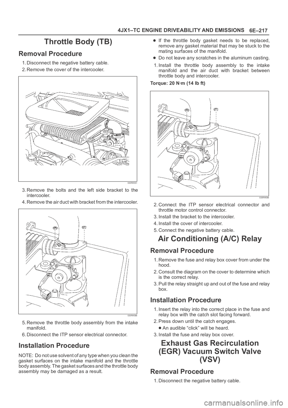
Removal Procedure
1. Disconnect the negative battery cable.
2. Remove the cover of the intercooler.
035RW051
3. Remove the bolts and the left side bracket to the
intercooler.
4 . R e m o v e t h e a i r d u c t w i t h b r a c k e t f r o m t h e i n t e r c o o l e r.
035RW086
5. Remove the throttle body assembly from the intake
manifold.
6. Disconnect the ITP sensor electrical connector.
Installation Procedure
NOTE: Do not use solvent of any type when you clean the
gasket surfaces on the intake manifold and the throttle
body assembly. The gasket surfaces and the throttle body
assembly may be damaged as a result.
If the throttle body gasket needs to be replaced,
remove any gasket material that may be stuck to the
mating surfaces of the manifold.
Do not leave any scratches in the aluminum casting.
1. Install the throttle body assembly to the intake
manifold and the air duct with bracket between
throttle body and intercooler.
Torque: 20 Nꞏm (14 Ib ft)
035RW086
2. Connect the ITP sensor electrical connector and
throttle motor control connector.
3. Install the bracket to the intercooler.
4. Install the cover of intercooler.
5. Connect the negative battery cable.
Air Conditioning (A/C) Relay
Removal Procedure
1. Remove the fuse and relay box cover from under the
hood.
2. Consult the diagram on the cover to determine which
is the correct relay.
3. Pull the relay straight up and out of the fuse and relay
box.
Installation Procedure
1. Insert the relay into the correct place in the fuse and
relay box with the catch slot facing forward.
2. Press down until the catch engages.
An audible “click” will be heard.
3. Install the fuse and relay box cover.
Exhaust Gas Recirculation
(EGR) Vacuum Switch Valve
(VSV)
Removal Procedure
1. Disconnect the negative battery cable.
Page 2597 of 6000
The chassis electrical system is a 12–volt system with a
negative ground polarity.
Wire size are appropriate to respective circuits, and
classified by color. (The classification of harnesses by
color is shown on the circuit diagram for ease of harness
identification.)
The wire size is determined by load capacity and the
length of wire required.
The vehicle harnesses are: body harness, chassis
harness, engine room harness, instrument harness,
transmission harness, engine ECGI harness, dome light
harness, door harness, rear body harness, tailgate
harness, SRS harness and battery cables.
The harnesses are protected either by tape or corrugated
tube, depending on harness location.
The circuit for each system consists of the power source,
wire, fuse, relay, switch, load parts and ground, all of
which are shown on the circuit diagram.
In this section, each electrical device is classified by
system.
For major parts shown on the circuit based on the circuit
diagram for each system, a summary, diagnosis of
troubles and inspection procedures are detailed.
Notes for Working on Electrical
Items
Disconnecting the Battery Cable
1. All switches should be in the “OFF” position.
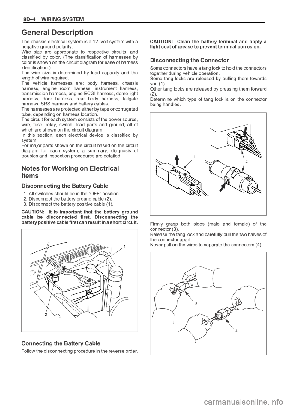
2. Disconnect the battery ground cable (2).
3. Disconnect the battery positive cable (1).
CAUTION: It is important that the battery ground
cable be disconnected first. Disconnecting the
battery positive cable first can result in a short circuit.
Connecting the Battery Cable
Follow the disconnecting procedure in the reverse order.CAUTION: Clean the battery terminal and apply a
light coat of grease to prevent terminal corrosion.
Disconnecting the Connector
Some connectors have a tang lock to hold the connectors
together during vehicle operation.
Some tang locks are released by pulling them towards
you (1).
Other tang locks are released by pressing them forward
(2).
Determine which type of tang lock is on the connector
being handled.
Firmly grasp both sides (male and female) of the
connector (3).
Release the tang lock and carefully pull the two halves of
the connector apart.
Never pull on the wires to separate the connectors (4).
2
1
General Description
1
2
3
4
Page 4658 of 6000
6E–1 ENGINE DRIVEABILITY AND EMISSIONS
ENGINE
ENGINE DRIVEABILITY AND EMISSIONS
CONTENTS
Specifications 6E–5. . . . . . . . . . . . . . . . . . . . . . . . .
Tightening Specifications 6E–5. . . . . . . . . . . . . . .
Vehicle Type Specifications 6E–5. . . . . . . . . . . . .
Diagrams and Schematics 6E–6. . . . . . . . . . . . . . . .
PCM Wiring Diagram (1 of 11) 6E–6. . . . . . . . . . .
PCM Wiring Diagram (2 of 11) For EC,
THAILAND, SOUTH EAST ASIA, LATIN
AMERICA, GULF, SAUDI, CHINA. 6E–7. . . . . .
PCM Wiring Diagram (3 of 11) For SOUTH
AFRICA and EXP. 6E–8. . . . . . . . . . . . . . . . . . . . .
PCM Wiring Diagram (4 of 11) 6E–9. . . . . . . . . . .
PCM Wiring Diagram (5 of 11) 6E–10. . . . . . . . . . .
PCM Wiring Diagram (6 of 11) For
AUSTRALIA, THAILAND, SOUTH EAST
ASIA, LATIN AMERICA, GULF, SAUDI,
LATIN AMERICA. 6E–11. . . . . . . . . . . . . . . . . . . . .
PCM Wiring Diagram (7 of 11) For EC. 6E–12. . .
PCM Wiring Diagram (8 of 11) For EXPORT
and SOUTH AFRICA. 6E–13. . . . . . . . . . . . . . . . .
PCM Wiring Diagram (9 of 11) Except EXP
and SOUTH AFRICA 6E–14. . . . . . . . . . . . . . . . . .
PCM Wiring Diagram (10 of 11) For
EXPORT and SOUTH AFRICA 6E–15. . . . . . . . .
PCM Wiring Diagram (11 of 11) 6E–16. . . . . . . . . .
PCM Pinouts 6E–17. . . . . . . . . . . . . . . . . . . . . . . . . . .
PCM Pinout Table, 32-Way Red
Connector – Row “A” 6E–17. . . . . . . . . . . . . . . . . .
PCM Pinout Table, 32-Way Red
Connector – Row “B” 6E–19. . . . . . . . . . . . . . . . . .
PCM Pinout Table, 32-Way White
Connector – Row “C” (For EC) 6E–20. . . . . . . . . .
PCM Pinout Table, 32-Way White
Connector – Row “C” (For except EC) 6E–21. . .
PCM Pinout Table, 32-Way White
Connector – Row “D”
(For except EXPORT and SOUTH
AFRICA) 6E–22. . . . . . . . . . . . . . . . . . . . . . . . . . . . .
PCM Pinout Table, 32-Way White
Connector – Row “D”
(For EXPORT and SOUTH AFRICA) 6E–23. . . . .
PCM Pinout Table, 32-Way Blue
Connector – Row “E”
(For except EXPORT and SOUTH
AFRICA) 6E–24. . . . . . . . . . . . . . . . . . . . . . . . . . . . .
PCM Pinout Table, 32-Way Blue
Connector – Row “E”
(For EXPORT and SOUTH AFRICA) 6E–26. . . . .
PCM Pinout Table, 32-Way Blue
Connector – Row “F” 6E–27. . . . . . . . . . . . . . . . . .
Component Locators 6E–28. . . . . . . . . . . . . . . . . . . .
Engine Component Locator (This illustration
is based on RHD model.) 6E–28. . . . . . . . . . . . . . Engine Component Locator Table 6E–29. . . . . . . .
Engine Component Locator Table 6E–31. . . . . . . .
Undercarriage Component Locator 6E–32. . . . . .
Undercarriage Component Locator Table
(Automatic Transmission) 6E–32. . . . . . . . . . . . . .
Undercarriage Component Locator Table
(Manual Transmission) 6E–33. . . . . . . . . . . . . . . .
Fuse and Relay Panel (Underhood
Electrical Center) 6E–33. . . . . . . . . . . . . . . . . . . . .
Sensors and Miscellaneous Component
Locators 6E–34. . . . . . . . . . . . . . . . . . . . . . . . . . . . .
Diagnosis 6E–37. . . . . . . . . . . . . . . . . . . . . . . . . . . . . .
Strategy-Based Diagnostics 6E–37. . . . . . . . . . . . .
Strategy-Based Diagnostics 6E–37. . . . . . . . . . . . .
DTC Stored 6E–37
. . . . . . . . . . . . . . . . . . . . . . . . . . .
No DTC 6E–37. . . . . . . . . . . . . . . . . . . . . . . . . . . . . .
No Matching Symptom 6E–37. . . . . . . . . . . . . . . . .
Intermittents 6E–37. . . . . . . . . . . . . . . . . . . . . . . . . .
No Trouble Found 6E–37. . . . . . . . . . . . . . . . . . . . .
Verifying Vehicle Repair 6E–37. . . . . . . . . . . . . . . .
General Service Information 6E–38. . . . . . . . . . . . . .
OBD Serviceablity Issues 6E–38. . . . . . . . . . . . . . .
Maintenance Schedule 6E–38. . . . . . . . . . . . . . . . .
Visual / Physical Engine Compartment
Inspection 6E–38. . . . . . . . . . . . . . . . . . . . . . . . . . . .
Basic Knowledge of Tools Required 6E–38. . . . . .
Serial Data Communications 6E–38. . . . . . . . . . . . . .
Class II Serial Data Communications 6E–38. . . . .
On-Board Diagnostic (OBD) 6E–39. . . . . . . . . . . . . .
On-Board Diagnostic Tests 6E–39. . . . . . . . . . . . .
Comprehensive Component Monitor
Diagnostic Operation 6E–39. . . . . . . . . . . . . . . . . .
Common OBD Terms 6E–40. . . . . . . . . . . . . . . . . .
The Diagnostic Executive 6E–40. . . . . . . . . . . . . . .
DTC Types 6E–41. . . . . . . . . . . . . . . . . . . . . . . . . . .
Verifying Vehicle Repair 6E–42. . . . . . . . . . . . . . . .
Reading Diagnostic Trouble Codes Using
A Tech 2 6E–42. . . . . . . . . . . . . . . . . . . . . . . . . . . . .
Tech 2 Tech 2 6E–43. . . . . . . . . . . . . . . . . . . . . . . . .
Tech 2 Features 6E–43. . . . . . . . . . . . . . . . . . . . . . .
Getting Started 6E–44. . . . . . . . . . . . . . . . . . . . . . . .
Operating Procedure (For Example) 6E–44. . . . .
DTC Modes 6E–45. . . . . . . . . . . . . . . . . . . . . . . . . . .
DTC Information Mode 6E–46. . . . . . . . . . . . . . . . .
Injector Balance Test 6E–46. . . . . . . . . . . . . . . . . . .
EGR Control Test 6E–47. . . . . . . . . . . . . . . . . . . . . .
Idle Air Control System Test 6E–48. . . . . . . . . . . . .
Page 4976 of 6000
6E–319 ENGINE DRIVEABILITY AND EMISSIONS
Fuel Pump Relay
Removal Procedure
1. Remove the fuse and relay box cover from under the
hood.
2. Consult the diagram on the cover to determine which
is the correct relay.
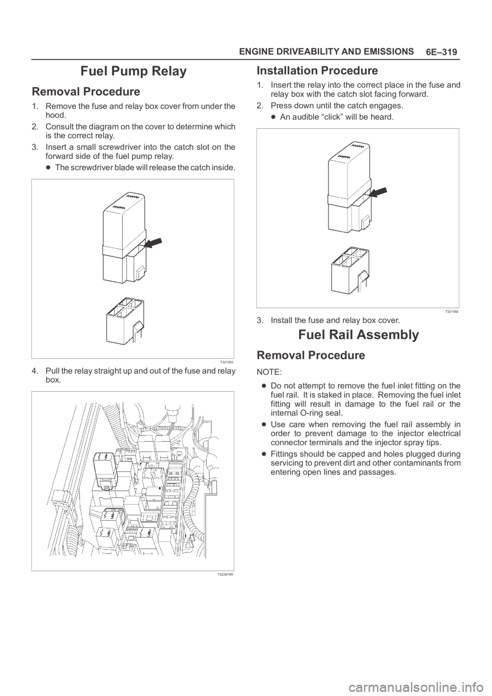
3. Insert a small screwdriver into the catch slot on the
forward side of the fuel pump relay.
The screwdriver blade will release the catch inside.
T321092
4. Pull the relay straight up and out of the fuse and relay
box.
TS23976R
Installation Procedure
1. Insert the relay into the correct place in the fuse and
relay box with the catch slot facing forward.
2. Press down until the catch engages.
An audible “click” will be heard.
T321092
3. Install the fuse and relay box cover.
Fuel Rail Assembly
Removal Procedure
NOTE:
Do not attempt to remove the fuel inlet fitting on the
fuel rail. It is staked in place. Removing the fuel inlet
fitting will result in damage to the fuel rail or the
internal O-ring seal.
Use care when removing the fuel rail assembly in
order to prevent damage to the injector electrical
connector terminals and the injector spray tips.
Fittings should be capped and holes plugged during
servicing to prevent dirt and other contaminants from
entering open lines and passages.
Page 4982 of 6000
6E–325 ENGINE DRIVEABILITY AND EMISSIONS
Spark Plug Gap Check
Check the gap of all spark plugs before installation.
Use a round wire feeler gauge to ensure an accurate
check.
Plugs installed with the wrong gap can cause poor
engine performance and excessive emissions.
Installation Procedure
NOTE: The plug must thread smoothly into the cylinder
head and be fully seated. Use a thread chaser if
necessary to clean the threads in the cylinder head.
Cross-threading or failure to fully seat the spark plug can
cause plug overheating, exhaust blow-by gas, or thread
damage. Do not overtighten the spark plugs. Over
tightening can cause aluminum threads to strip.
1. Install the spark plug in the engine. Use the
appropriate spark plug socket.
Tighten
Tighten the spark plug to 18 Nꞏm (13 lb ft.).
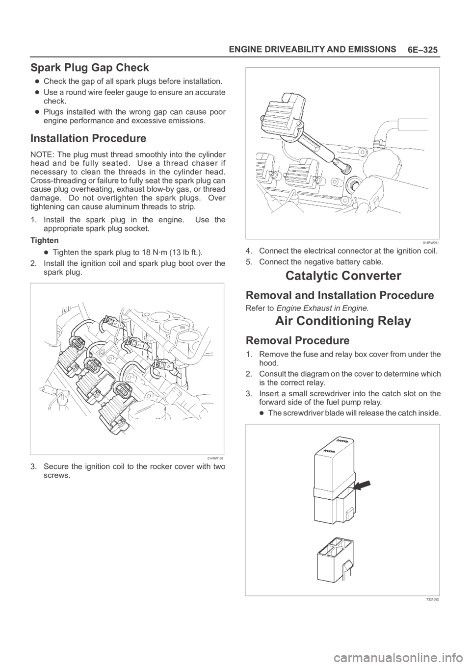
2. Install the ignition coil and spark plug boot over the
spark plug.
014RW108
3. Secure the ignition coil to the rocker cover with two
screws.
014RW091
4. Connect the electrical connector at the ignition coil.
5. Connect the negative battery cable.
Catalytic Converter
Removal and Installation Procedure
Refer to Engine Exhaust in Engine.
Air Conditioning Relay
Removal Procedure
1. Remove the fuse and relay box cover from under the
hood.
2. Consult the diagram on the cover to determine which
is the correct relay.
3. Insert a small screwdriver into the catch slot on the
forward side of the fuel pump relay.
The screwdriver blade will release the catch inside.
T321092
Page 5404 of 6000
ENGINE ELECTRICAL 6D – 1
ENGINE ELECTRICAL
CONTENTS
Battery . . . . . . . . . . . . . . . . . . . . . . . . . . . . 6D–1
General Description . . . . . . . . . . . . . . . . 6D–1
Diagnosis . . . . . . . . . . . . . . . . . . . . . . . . 6D–1
On Vehicle Service . . . . . . . . . . . . . . . . . 6D–3
Main Data and Specification . . . . . . . . . . 6D–4
Starting System . . . . . . . . . . . . . . . . . . . . . 6D–5
General Description . . . . . . . . . . . . . . . . 6D–5
On Vehicle Service . . . . . . . . . . . . . . . . . 6D–7
Starter . . . . . . . . . . . . . . . . . . . . . . . . . . 6D–7
Unit Repair . . . . . . . . . . . . . . . . . . . . . . . 6D–8Charging System . . . . . . . . . . . . . . . . . . . . 6D–15
General Description . . . . . . . . . . . . . . . . 6D–15
Diagnosis . . . . . . . . . . . . . . . . . . . . . . . . 6D–16
Unit Repair . . . . . . . . . . . . . . . . . . . . . . . 6D–17
Main Data and Specification . . . . . . . . . . 6D–22
QOS4 Preheating System . . . . . . . . . . . . . . 6D–23
General Description . . . . . . . . . . . . . . . . 6D–23
System Diagram . . . . . . . . . . . . . . . . . . . 6D–23
Inspection of QOS4 System Operation . . 6D–24
BATTERY
GENERAL DESCRIPTION
DIAGNOSIS
There are six battery fluid caps at the top of the battery.
These are covered by a paper label.
The battery is completely sealed except for the six
small vent holes at the side. These vent holes permit
the escape of small amounts of gas generated by the
battery.
This type of battery has the following advantages over
conventional batteries:1. There is no need to add water during the entire
service life of the battery.
2. The battery protects itself against overcharging.
The battery will refuse to accept an excessive
charge.
(A conventional battery will accept an excessive
charge, resulting in gassing and loss of battery
fluid.)
3. The battery is much less vulnerable to self-
discharge than a conventional type battery.
1. VISUAL INSPECTION (Step 1)
Inspect the battery for obvious physical damage, such
as a cracked or broken case, which would permit
electrolyte loss.
Replace the battery if obvious physical damage is
discovered during inspection.
Check for any other physical damage and correct it as
necessary. If not, proceed to Step 2.
2. HYDROMETER CHECK (Step 2)
There is a built-in hydrometer (Charge test indicator) at
the top of the battery. It is designed to be used during
diagnostic procedures.
Before trying to read the hydrometer, carefully clean the
upper battery surface.
If your work area is poorly lit, additional light may be
necessary to read the hydrometer.
a. BLUE RING OR DOT VISIBLE – Go to Step 4.
b. BLUE RING OR DOT NOT VISIBLE – Go to
Step 3.3. FLUID LEVEL CHECK (Step 3)
The fluid level should be between the upper level line
and lower level line on side of the battery.
a. CORRECT FLUID LEVEL – Charge the battery.
b. BELOW LOWER LEVEL – Replace battery.
4. VOLTAGE CHECK (Step 4)
(1) Put voltmeter test leads to battery terminals.
a. VOLTAGE IS 12.4V OR ABOVE – Go to Step 5.
b. VOLTAGE IS UNDER 12.4V – Go to procedure
(2) below.
(2) Determine fast charge amperage from
specification. (See Main Data and Specifications in
this section.)
Fast charge battery for 30 minutes at amperage
rate no higher than specified value.
Take voltage and amperage readings after charge.
a. VOLTAGE IS ABOVE 16V AT BELOW 1/3 OF
AMPERAGE RATE – Replace battery.