Seat OPEL FRONTERA 1998 User Guide
[x] Cancel search | Manufacturer: OPEL, Model Year: 1998, Model line: FRONTERA, Model: OPEL FRONTERA 1998Pages: 6000, PDF Size: 97 MB
Page 774 of 6000

4D2–7 TRANSFER CASE (TOD)
TOD ECU
Removal
1. Disconnect the ground cable.
2. Move the right-hand seat forward and remove the
second seat foot rest (1).
3. Disconnect the connector from the ECU (2).
4. Remove the bolts and detach the ECU (2) from the
bracket.
F07RW021
Installation
1. Perform the removal step in reverse order.
Page 815 of 6000
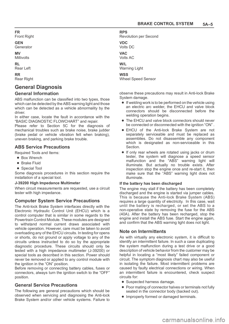
5A–5 BRAKE CONTROL SYSTEM
FR
Front Right
GEN
Generator
MV
Millivolts
RL
Rear Left
RR
Rear RightRPS
Revolution per Second
VDC
Vo l t s D C
VA C
Vo l t s A C
W/L
Warning Light
WSS
Wheel Speed Sensor
General Diagnosis
General Information
ABS malfunction can be classified into two types, those
which can be detected by the ABS warning light and those
which can be detected as a vehicle abnormality by the
driver.
In either case, locate the fault in accordance with the
“BASIC DIAGNOSTIC FLOWCHART” and repair.
Please refer to Section 5C for the diagnosis of
mechanical troubles such as brake noise, brake judder
(brake pedal or vehicle vibration felt when braking),
uneven braking, and parking brake trouble.
ABS Service Precautions
Required Tools and Items:
Box Wrench
Brake Fluid
Special Tool
Some diagnosis procedures in this section require the
installation of a special tool.
J-39200 High Impedance Multimeter
When circuit measurements are requested, use a circuit
tester with high impedance.
Computer System Service Precautions
The Anti-lock Brake System interfaces directly with the
Electronic Hydraulic Control Unit (EHCU) which is a
control computer that is similar in some regards to the
Powertrain Control Module. These modules are designed
to withstand normal current draws associated with
vehicle operation. However, care must be taken to avoid
overloading any of the EHCU circuits. In testing for opens
or shorts, do not ground or apply voltage to any of the
circuits unless instructed to do so by the appropriate
diagnostic procedure. These circuits should only be
tested with a high impedance multimeter (J-39200) or
special tools as described in this section. Power should
never be removed or applied to any control module with
the ignition in the “ON” position.
Before removing or connecting battery cables, fuses or
connectors, always turn the ignition switch to the “OFF”
position.
General Service Precautions
The following are general precautions which should be
observed when servicing and diagnosing the Anti-lock
Brake System and/or other vehicle systems. Failure toobserve these precautions may result in Anti-lock Brake
System damage.
If welding work is to be performed on the vehicle using
an electric arc welder, the EHCU and valve block
connectors should be disconnected before the
welding operation begins.
The EHCU and valve block connectors should never
be connected or disconnected with the ignition “ON” .
EHCU of the Anti-lock Brake System are not
separately serviceable and must be replaced as
assemblies. Do not disassemble any component
which is designated as non-serviceable in this
Section.
If only rear wheels are rotated using jacks or drum
tester, the system will diagnose a speed sensor
malfunction and the “ABS” warning light will
illuminate. But actually no trouble exists. After
inspection stop the engine once and re-start it, then
make sure that the “ABS” warning light does not
illuminate.
If the battery has been discharged
The engine may stall if the battery has been completely
discharged and the engine is started via jumper cables.
This is because the Anti-lock Brake System (ABS)
requires a large quantity of electricity. In this case, wait
until the battery is recharged, or set the ABS to a
non-operative state by removing the fuse for the ABS
(40A). After the battery has been recharged, stop the
engine and install the ABS fuse. Start the engine again,
and confirm that the ABS warning light does not light.
Note on Intermittents
As with virtually any electronic system, it is difficult to
identify an intermittent failure. In such a case duplicating
the system malfunction during a test drive or a good
description of vehicle behavior from the customer may be
helpful in locating a “most likely” failed component or
circuit. The symptom diagnosis chart may also be useful
in isolating the failure. Most intermittent problems are
caused by faulty electrical connections or wiring. When
an intermittent failure is encountered, check suspect
circuits for:
Suspected harness damage.
Poor mating of connector halves or terminals not fully
seated in the connector body (backed out).
Improperly formed or damaged terminals.
Page 961 of 6000
6A–5
ENGINE MECHANICAL
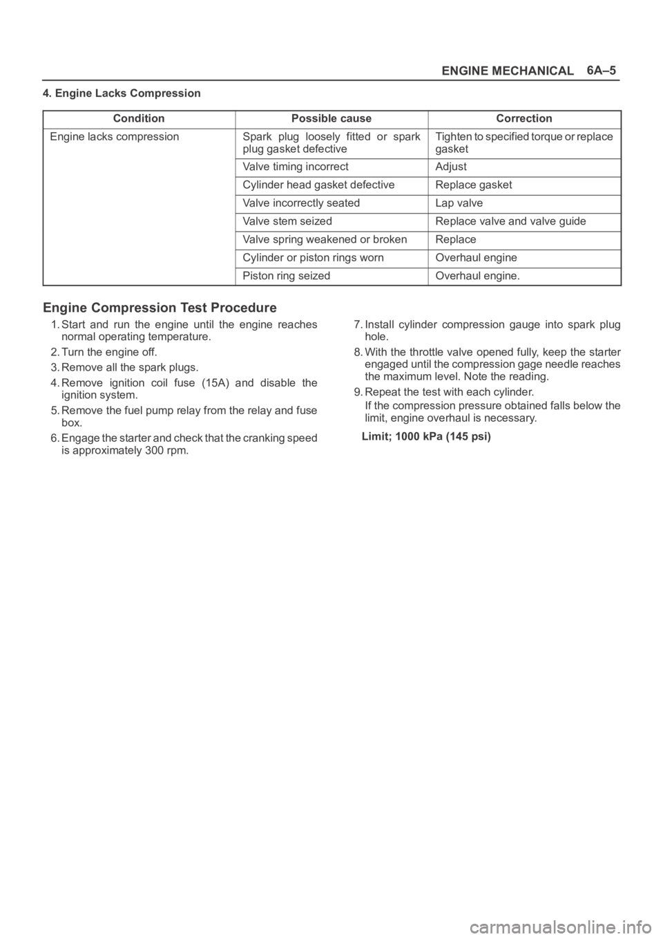
4. Engine Lacks Compression
Condition
Possible causeCorrection
Engine lacks compressionSpark plug loosely fitted or spark
plug gasket defectiveTighten to specified torque or replace
gasket
Valve timing incorrectAdjust
Cylinder head gasket defectiveReplace gasket
Valve incorrectly seatedLap valve
Valve stem seizedReplace valve and valve guide
Valve spring weakened or brokenReplace
Cylinder or piston rings wornOverhaul engine
Piston ring seizedOverhaul engine.
Engine Compression Test Procedure
1. Start and run the engine until the engine reaches
normal operating temperature.
2. Turn the engine off.
3. Remove all the spark plugs.
4. Remove ignition coil fuse (15A) and disable the
ignition system.
5. Remove the fuel pump relay from the relay and fuse
box.
6. Engage the starter and check that the cranking speed
is approximately 300 rpm.7. Install cylinder compression gauge into spark plug
hole.
8. With the throttle valve opened fully, keep the starter
engaged until the compression gage needle reaches
the maximum level. Note the reading.
9. Repeat the test with each cylinder.
If the compression pressure obtained falls below the
limit, engine overhaul is necessary.
Limit; 1000 kPa (145 psi)
Page 963 of 6000
6A–7
ENGINE MECHANICAL
Condition CorrectionPossible cause
OthersEngine lacks compressionRefer to “Hard Start”
Valve incorrectly seatedLap valve
Air Cleaner Filter cloggedReplace filter element
Valve timing incorrectReadjust
Idle air control valve brokenReplace
Fast idle solenoid defectiveReplace
Positive Crankcase Ventilation valve
defective or cloggedReplace
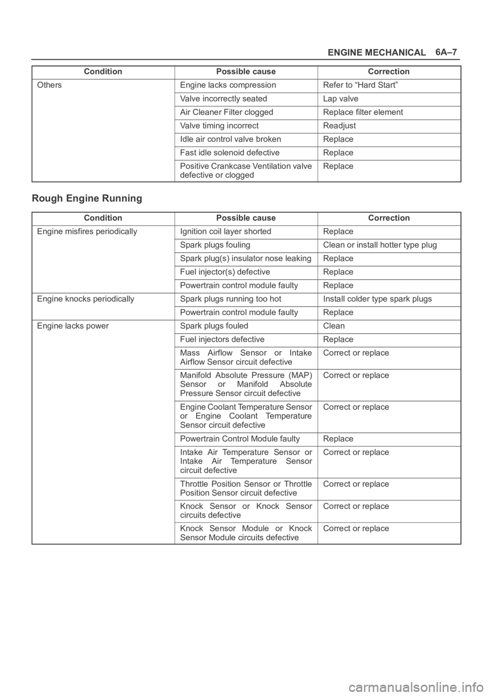
Rough Engine Running
ConditionPossible causeCorrection
Engine misfires periodicallyIgnition coil layer shortedReplace
Spark plugs foulingClean or install hotter type plug
Spark plug(s) insulator nose leakingReplace
Fuel injector(s) defectiveReplace
Powertrain control module faultyReplace
Engine knocks periodicallySpark plugs running too hotInstall colder type spark plugs
Powertrain control module faultyReplace
Engine lacks powerSpark plugs fouledClean
Fuel injectors defectiveReplace
Mass Airflow Sensor or Intake
Airflow Sensor circuit defectiveCorrect or replace
Manifold Absolute Pressure (MAP)
Sensor or Manifold Absolute
Pressure Sensor circuit defectiveCorrect or replace
Engine Coolant Temperature Sensor
or Engine Coolant Temperature
Sensor circuit defectiveCorrect or replace
Powertrain Control Module faultyReplace
Intake Air Temperature Sensor or
Intake Air Temperature Sensor
circuit defectiveCorrect or replace
Throttle Position Sensor or Throttle
Position Sensor circuit defectiveCorrect or replace
Knock Sensor or Knock Sensor
circuits defectiveCorrect or replace
Knock Sensor Module or Knock
Sensor Module circuits defectiveCorrect or replace
Page 968 of 6000

6A–12
ENGINE MECHANICAL
ConditionPossible causeCorrection
Noise from connecting rods or from
connecting rod bearings
(Faulty connecting rods orBearing or crankshaft pin wornReplace connecting rod bearings
and crankshaft or regrind crankshaft
pin and install the undersize bearing
yg
connecting rod bearings usually
make an abnormal noise slightly
higher than the crank bearing noise,
which becomes more evident when
Crankpin out of roundReplace connecting rod bearings
and crankshaft or regrind crankshaft
pin and install the undersize bearing
which becomes more evident when
engine is accelerated)Connecting rod bentCorrect or replaceg)
Connecting rod bearing seizedReplace connecting rod bearings
and crankshaft or regrind crankshaft
pin and install the undersize bearing
Troubleshooting Procedure
Abnormal noise stops when the spark plug on the cylinder
with defective part is shorted out.
Condition
Possible causeCorrection
Piston and cylinder noise
(Faulty piston or cylinder usually
kbidhil
Piston clearance increased due to
cylinder wearReplace piston and cylinder body
makes a combined mechanical
thumping noise which increasesPiston seizedReplace piston and cylinder bodyg
when engine is suddenly accelerated
but diminishes
gradually as thePiston ring brokenReplace piston and cylinder bodybut diminishes gradually as the
engine warms up)Piston defectiveReplace pistons and others
Troubleshooting Procedure
Short out each spark plug and listen for change in engine
noise.
Condition
Possible causeCorrection
Piston pin noise
(Piston makes noise each time it
goes up and down)Piston pin or piston pin hole wornReplace piston, piston pin and
connecting rod assy
Troubleshooting Procedure
The slapping sound stops when spark plug on bad
cylinder is shorted out.
Condition
Possible causeCorrection
Timing belt noiseTiming belt tension is incorrectReplace pusher or adjust the tension
pulley or replace timing belt
Tensioner bearing defectiveReplace
Timing belt defectiveReplace
Timing pulley defectiveReplace
Timing belt comes in contact with
timing coverReplace timing belt and timing cover
Valve noiseValve clearance incorrectReplace adjusting shim
Valve and valve guide seizedReplace valve and valve guide
Valve spring broken or weakenedReplace
Valve seat off–positionedCorrect
Camshaft worn outReplace
Crankshaft noiseCrankshaft end play excessive
(noise occurs when clutch is
engaged)Replace thrust bearing
Page 970 of 6000
6A–14
ENGINE MECHANICAL
Condition CorrectionPossible cause
Trouble in emission control systemHeated Oxygen Sensor circuit openCorrect or replace
Heated Oxygen Sensor defectiveReplace
Signal vacuum hose loosely fitted or
defectiveCorrect or replace
EGR Valve circuit open or shortedCorrect or replace
Exhaust Gas Recirculation Valve
defectiveReplace
ECT Sensor circuit open or shortedCorrect or replace
Canister Purge Valve circuit open or
shortedCorrect or replace
Canister Purge Valve defectiveReplace
ECT Sensor defectiveReplace
Positive Crankcase Ventilation
(PCV) valve and hose cloggedCorrect or replace
Evaporator systemRefer to Section 6E
Trouble in ignition system————Refer to “Engine Lacks Power”
Trouble in cylinder head partsCarbon deposits in combustion
chamberRemove carbon
Carbon deposit on valve, valve seat
and valve guideRemove carbon
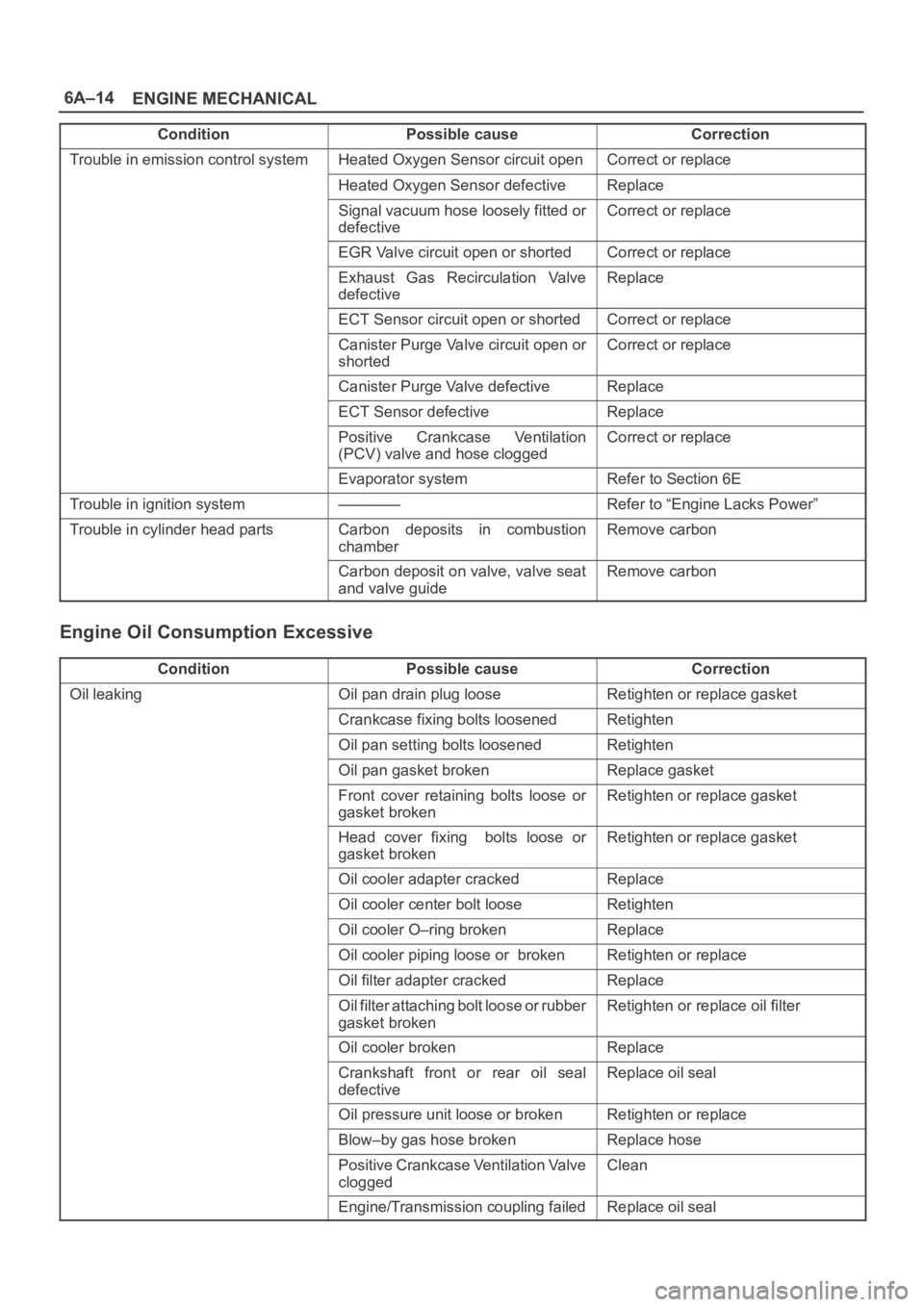
Engine Oil Consumption Excessive
ConditionPossible causeCorrection
Oil leakingOil pan drain plug looseRetighten or replace gasket
Crankcase fixing bolts loosenedRetighten
Oil pan setting bolts loosenedRetighten
Oil pan gasket brokenReplace gasket
Front cover retaining bolts loose or
gasket brokenRetighten or replace gasket
Head cover fixing bolts loose or
gasket brokenRetighten or replace gasket
Oil cooler adapter crackedReplace
Oil cooler center bolt looseRetighten
Oil cooler O–ring brokenReplace
Oil cooler piping loose or brokenRetighten or replace
Oil filter adapter crackedReplace
Oil filter attaching bolt loose or rubber
gasket brokenRetighten or replace oil filter
Oil cooler brokenReplace
Crankshaft front or rear oil seal
defectiveReplace oil seal
Oil pressure unit loose or brokenRetighten or replace
Blow–by gas hose brokenReplace hose
Positive Crankcase Ventilation Valve
cloggedClean
Engine/Transmission coupling failedReplace oil seal
Page 995 of 6000

6A–39
ENGINE MECHANICAL
Valve Stem Oil Controller , Valve Spring and Valve Guide
Removal
1. Disconnect battery ground cable.
2. Drain engine oil.
Drain engine coolant.
3. Remove cylinder head assembly.
Refer to removal procedure for Cylinder Head in
this manual.
4. Remove camshaft.
Refer to removal procedure for Camshaft in this
manual.
5. Remove tappets with shim.
NOTE: Do not damage shim surface.
6. Remove valve springs using 5–8840–2446–0 valve
spring compressor and 5–8840–2547–0 valve spring
compressor adapter then remove upper valve spring
seat and lower seat.
014RW042
7. Remove oil controller using 5–8840–0623–0 oil
controller remover, remove each valve stem oil
controller.
8. Remove valve guide using 5–8840–2549–0 valve
guide replacer.
Installation
1. Install valve guide using 5–8840–2442–0 valve guide
installer.
2. Install oil controller using 5–8840–0624–0 oil
controller installer.
3. Install lower valve spring seat, valve spring and upper
valve spring seat then put split collars on the upper
spring seat, using 5–8840–2446–0 valve spring
compressor and 5–8840–2547–0 valve spring
compressor adapter to install the split collars.
014RW042
4. Install tappet with shim.
5. Install camshaft assembly.
Refer to installation procedure for Camshaft in this
manual.
6. Install cylinder head assembly.
Refer to installation procedure for Cylinder Head in
this manual.
7. Fill engine oil until full level.
8. Fill engine coolant.
Page 997 of 6000
6A–41
ENGINE MECHANICAL
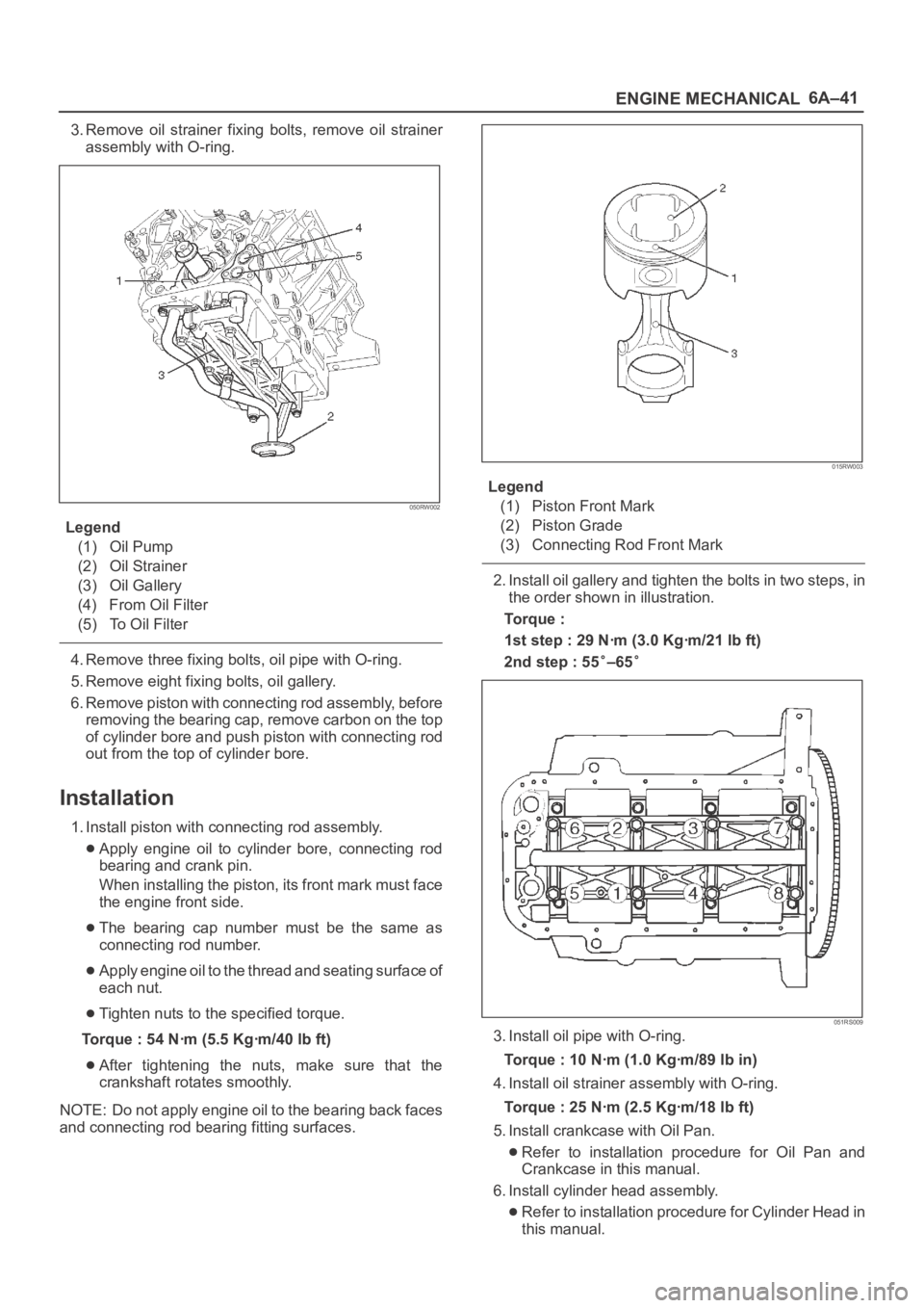
3. Remove oil strainer fixing bolts, remove oil strainer
assembly with O-ring.
050RW002
Legend
(1) Oil Pump
(2) Oil Strainer
(3) Oil Gallery
(4) From Oil Filter
(5) To Oil Filter
4. Remove three fixing bolts, oil pipe with O-ring.
5. Remove eight fixing bolts, oil gallery.
6. Remove piston with connecting rod assembly, before
removing the bearing cap, remove carbon on the top
of cylinder bore and push piston with connecting rod
out from the top of cylinder bore.
Installation
1. Install piston with connecting rod assembly.
Apply engine oil to cylinder bore, connecting rod
bearing and crank pin.
When installing the piston, its front mark must face
the engine front side.
The bearing cap number must be the same as
connecting rod number.
Apply engine oil to the thread and seating surface of
each nut.
Tighten nuts to the specified torque.
Torque : 54 Nꞏm (5.5 Kgꞏm/40 lb ft)
After tightening the nuts, make sure that the
crankshaft rotates smoothly.
NOTE: Do not apply engine oil to the bearing back faces
and connecting rod bearing fitting surfaces.
015RW003
Legend
(1) Piston Front Mark
(2) Piston Grade
(3) Connecting Rod Front Mark
2. Install oil gallery and tighten the bolts in two steps, in
the order shown in illustration.
To r q u e :
1st step : 29 Nꞏm (3.0 Kgꞏm/21 lb ft)
2nd step : 55
–65
051RS009
3. Install oil pipe with O-ring.
Torque : 10 Nꞏm (1.0 Kgꞏm/89 lb in)
4. Install oil strainer assembly with O-ring.
Torque : 25 Nꞏm (2.5 Kgꞏm/18 lb ft)
5. Install crankcase with Oil Pan.
Refer to installation procedure for Oil Pan and
Crankcase in this manual.
6. Install cylinder head assembly.
Refer to installation procedure for Cylinder Head in
this manual.
Page 999 of 6000
6A–43
ENGINE MECHANICAL
6. Remove oil pump assembly.
Refer to removal procedure for Oil Pump in this
manual.
7. Remove cylinder body side bolts.
8. Remove oil gallery.
9. Remove flywheel.
10. Remove rear oil seal retainer.
Refer to removal procedure for Rear Oil Seal in this
manual.
11. Remove connecting rod caps.
12. Remove crankshaft main bearing caps.
13. Remove crankshaft and main bearings.
Installation
1. Install crankshaft and main bearings.
Install main bearing in the cylinder block and main
bearing cap respectively.
Apply new engine oil to upper and lower main
bearings.
NOTE:
Do not apply engine oil to the bearing back faces.
Make sure that main bearings are in correct position.
Install crankshaft with care.
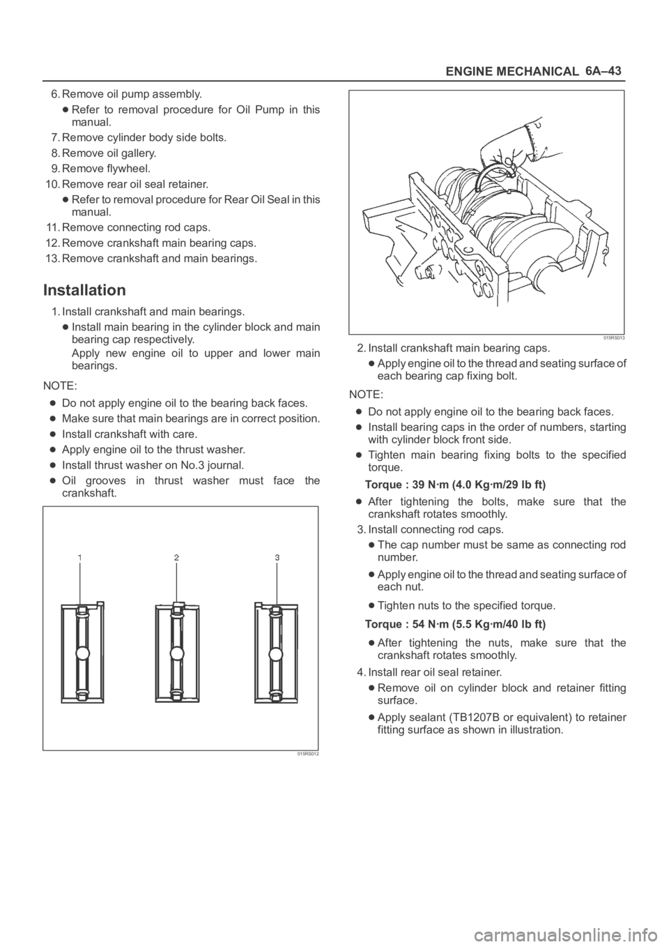
Apply engine oil to the thrust washer.
Install thrust washer on No.3 journal.
Oil grooves in thrust washer must face the
crankshaft.
015RS012
015RS013
2. Install crankshaft main bearing caps.
Apply engine oil to the thread and seating surface of
each bearing cap fixing bolt.
NOTE:
Do not apply engine oil to the bearing back faces.
Install bearing caps in the order of numbers, starting
with cylinder block front side.
Tighten main bearing fixing bolts to the specified
torque.
Torque : 39 Nꞏm (4.0 Kgꞏm/29 lb ft)
After tightening the bolts, make sure that the
crankshaft rotates smoothly.
3. Install connecting rod caps.
The cap number must be same as connecting rod
number.
Apply engine oil to the thread and seating surface of
each nut.
Tighten nuts to the specified torque.
Torque : 54 Nꞏm (5.5 Kgꞏm/40 lb ft)
After tightening the nuts, make sure that the
crankshaft rotates smoothly.
4. Install rear oil seal retainer.
Remove oil on cylinder block and retainer fitting
surface.
Apply sealant (TB1207B or equivalent) to retainer
fitting surface as shown in illustration.
Page 1008 of 6000

6A–52
ENGINE MECHANICAL
Cylinder Head
Cylinder Head and Associated Parts
011RW008
Legend
(1) Spark Plug
(2) Cylinder Head Bolt
(3) Camshaft Drive Gear Pulley Fixing Bolt
(4) Camshaft Drive Gear Pulley
(5) Camshaft Bracket Fixing Bolt
(6) Camshaft Bracket
(7) Camshaft Exhaust(8) Camshaft Intake
(9) Retainer Fixing Bolt
(10) Retainer Assembly
(11) Tappet with Shim
(12) Split Collar
(13) Valve Spring and Spring Upper Seat
(14) Valve
Disassembly
NOTE:
During disassembly, be sure that the valve train
components are kept together and identified so that
they can be reinstalled in their original locations.
Before removing the cylinder head from the engine
and before disassembling the valve mechanism,
perform a compression test and note the results.
1. Remove camshaft drive gear pulley fixing bolt (3),
then pulley (4).