Seat OPEL FRONTERA 1998 Service Manual
[x] Cancel search | Manufacturer: OPEL, Model Year: 1998, Model line: FRONTERA, Model: OPEL FRONTERA 1998Pages: 6000, PDF Size: 97 MB
Page 1416 of 6000

6E–299 ENGINE DRIVEABILITY AND EMISSIONS
damage, therefore, it is important to use care when
handling and testing electronic components.
NOTE: To prevent possible Electrostatic Discharge
damage, follow these guidelines:
Do not touch the control module connector pins or
soldered components on the control module circuit
board.
Do not open the replacement part package until the
part is ready to be installed.
Before removing the part from the package, ground
the package to a known good ground on the vehicle.
If the part has been handled while sliding across the
seat, or while sitting down from a standing position, or
while walking a distance, touch a known good ground
before installing the part.
NOTE: To prevent internal PCM damage, the ignition
must be in the “OFF” position in order to disconnect or
reconnect power to the PCM (for example: battery cable,
PCM pigtail, PCM fuse, jumper cables, etc.).
IMPORTANT:When replacing the production PCM
with a service PCM, it is important to transfer the
broadcast code and production PCM number to the
service PCM label. This will allow positive identification of
PCM parts throughout the service life of the vehicle. Do
not record this information on the metal PCM cover.
IMPORTANT:The ignition should always be in the
“OFF” position in order to install or remove the PCM
connectors.
Service of the PCM should normally consist of either re-
placement of the PCM or EEPROM programming. If the
diagnostic procedures call for the PCM to be replaced,
the PCM should be checked first to ensure it is the correct
part. If it is, remove the faulty PCM and install the new
service PCM.
The service PCM EEPROM will not be programmed.
DTC P0601 indicates the check sum error.
Removal Procedure
1. Disconnect the negative battery cable.
2. Block the wheels.
3. Remove the front console assembly.
1. Remove the four screws.
TS23755
2. Remove the transfer shift lever knob by
unscrewing the knob.
3. Move the transmission gear selector out of the
park position.
4. Lift up sharply on the back edge of the assembly.
5. Disconnect the seat heater switch connectors (if
equipped).
6. Disconnect the POWER and WINTER switch
connectors.
7. Lift out the front console assembly.
TS23756
Page 1421 of 6000

6E–304
ENGINE DRIVEABILITY AND EMISSIONS
2. Install the air filter element in the air cleaner housing.
TS23794
3. Install the air cleaner lid on the MAF sensor and the air
cleaner housing.
TS23973
4. Tighten the clamp and secure the four latches
between the lid and the air cleaner housing.
Idle Air Control (IAC) Valve
Removal Procedure
1. Disconnect the negative battery cable.
2. Disconnect the IAC electrical connector.
3. Remove the bolts and the IAC valve from the throttle
body.
NOTE: Do not clean the IAC valve by soaking it in
solvent. The valve will be damaged as a result.
TS23745
Cleaning, Inspection, and
Measurement Procedure
Clean the IAC valve O-ring sealing surface, pintle
valve seat and air passage.
– Use carburetor cleaner and a parts cleaning brush to
remove carbon deposits. Do not use a cleaner that
contains methyl ethyl ketone. This is an extremely
strong solvent and not necessary for this type of
deposit.
– Shiny spots on the pintle are normal and do not
indicate misalignment or a bent pintle shaft.
– If the air passage has heavy deposits, remove the
throttle body for complete cleaning.
TS23746
Inspect the IAC valve O-ring for cuts, cracks, or
distortion. Replace the O-ring if damaged.
Page 1442 of 6000

6E–325 ENGINE DRIVEABILITY AND EMISSIONS
Spark Plug Gap Check
Check the gap of all spark plugs before installation.
Use a round wire feeler gauge to ensure an accurate
check.
Plugs installed with the wrong gap can cause poor
engine performance and excessive emissions.
Installation Procedure
NOTE: The plug must thread smoothly into the cylinder
head and be fully seated. Use a thread chaser if
necessary to clean the threads in the cylinder head.
Cross-threading or failure to fully seat the spark plug can
cause plug overheating, exhaust blow-by gas, or thread
damage. Do not overtighten the spark plugs. Over
tightening can cause aluminum threads to strip.
1. Install the spark plug in the engine. Use the
appropriate spark plug socket.
Tighten
Tighten the spark plug to 18 Nꞏm (13 lb ft.).
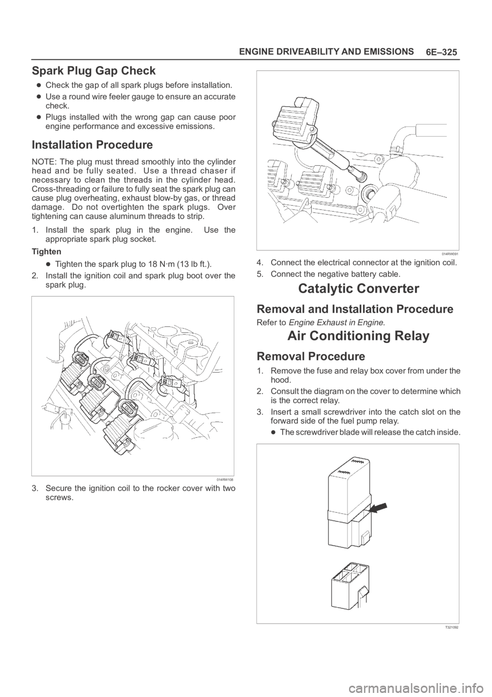
2. Install the ignition coil and spark plug boot over the
spark plug.
014RW108
3. Secure the ignition coil to the rocker cover with two
screws.
014RW091
4. Connect the electrical connector at the ignition coil.
5. Connect the negative battery cable.
Catalytic Converter
Removal and Installation Procedure
Refer to Engine Exhaust in Engine.
Air Conditioning Relay
Removal Procedure
1. Remove the fuse and relay box cover from under the
hood.
2. Consult the diagram on the cover to determine which
is the correct relay.
3. Insert a small screwdriver into the catch slot on the
forward side of the fuel pump relay.
The screwdriver blade will release the catch inside.
T321092
Page 1450 of 6000

6E–333 ENGINE DRIVEABILITY AND EMISSIONS
2. Use tool J 28742-A or the equivalent to remove the
pin and the sleeve terminals. Push on J 28742-A to
release.
NOTE: Do the use an ordinary pick or the terminal may
be bent or deformed. Unlike standard blade terminals,
these terminals cannot be straightened after they have
been improperly bent.
071
3. Cut the wire immediately behind the cable seal.
072
Installation Procedure
Make certain the connectors are properly seated and all
of the sealing rings are in place when you reconnect the
leads. The secondary lock hinge provides a backup
locking feature for the connector. The secondary lock
hinge is used for added reliability. This flap should retain
the terminals even if the small terminal lock tangs are not
positioned properly.
Do not replace the Weather-Pack connections with
standard connections. Read the instructions provided
with the Weather-Pack connector and terminal packages.
1. Replace the terminal.2. Slip the new seal onto the wire.
3. Strip 5 mm (0.2”) of insulation from the wire.
4. Crimp the terminal over the wire and the seal.
073
5. Push the terminal and the connector to engage the
locking tangs.
070
6. Close the secondary locking hinge.
Com-Pack III
General Information
The Com-Pack III terminal looks similar to some
Weather-Pack terminals. This terminal is not sealed and
is used where resistance to the environment is not
required. Use the standard method when repairing a
terminal. Do not use the Weather-Pack terminal tool J
28742-A or equivalent. These will damage the terminals.
Metri-Pack
Tools Required
J 35689 Terminal Remover
Page 1451 of 6000

6E–334
ENGINE DRIVEABILITY AND EMISSIONS
Removal Procedure
S o m e c o n n e c t o r s u s e t e r m i n a l s c a l l e d M e t r i - P a c k S e r i e s
150. These may be used at the engine coolant
temperature (ECT) sensor.
1. Slide the seal (1) back on the wire.
2. Insert the J 35689 tool or equivalent (3) in order to
release the terminal locking tang (2).
060
3. Push the wire and the terminal out through the
connector. If you reuse the terminal, reshape the
locking tang.
Installation Procedure
Metri-Pack terminals are also referred to as “pull-to-seat”
terminals.
1. In order to install a terminal on a wire, the wire must be
inserted through the seal (2) and through the
connector (3).
2. The terminal (1) is then crimped onto the wire.
061
3. Then the terminal is pulled back into the connector to
seat it in place.
Page 1458 of 6000

6E–341 ENGINE DRIVEABILITY AND EMISSIONS
this is done, if the problem still exists, it may be diagnosed
in the normal manner.
Electrostatic Discharge Damage
Electronic components used in the PCM are often
designed to carry very low voltage. Electronic
components are susceptible to damage caused by
electrostatic discharge. Less than 100 volts of static
electricity can cause damage to some electronic
components. By comparison, it takes as much as 4000
volts for a person to feel even the zap of a static
discharge.
TS23793
There are several ways for a person to become statically
charged. The most common methods of charging are by
friction and induction.
An example of charging by friction is a person sliding
across a vehicle seat.
Charge by induction occurs when a person with well
insulated shoes stands near a highly charged object
and momentary touches ground. Charges of the
same polarity are drained off leaving the person
highly charged with the opposite polarity. Static
charges can cause damage, therefore it is important
to use care when handling and testing electronic
components.
NOTE: To prevent possible electrostatic discharge
damage, follow these guidelines:
Do not touch the PCM connector pins or soldered
components on the PCM circuit board.
Do not touch the knock sensor module component
leads.
Do not open the replacement part package until the
part is ready to be installed.
Before removing the part from the package, ground
the package to a known good ground on the vehicle.
If the part has been handled while sliding across the
seat, while sitting down from a standing position, or
while walking a distance, touch a known good ground
before installing the part.
Upshift Lamp
Refer to Manual Transmission.
General Description (Air Induction)
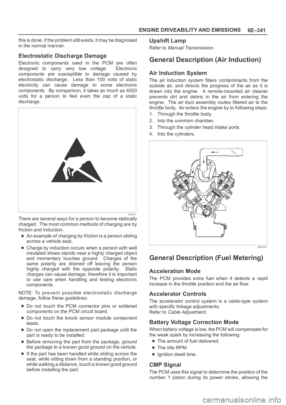
Air Induction System
The air induction system filters contaminants from the
outside air, and directs the progress of the air as it is
drawn into the engine. A remote-mounted air cleaner
prevents dirt and debris in the air from entering the
engine. The air duct assembly routes filtered air to the
throttle body. Air enters the engine by to following steps:
1. Through the throttle body.
2. Into the common chamber.
3. Through the cylinder head intake ports.
4. Into the cylinders.
055RV010
General Description (Fuel Metering)
Acceleration Mode
The PCM provides extra fuel when it detects a rapid
increase in the throttle position and the air flow.
Accelerator Controls
The accelerator control system is a cable-type system
with specific linkage adjustments.
Refer to
Cable Adjustment.
Battery Voltage Correction Mode
When battery voltage is low, the PCM will compensate for
the weak spark by increasing the following:
The amount of fuel delivered.
The idle RPM.
Ignition dwell time.
CMP Signal
The PCM uses this signal to determine the position of the
number 1 piston during its power stroke, allowing the
Page 1465 of 6000

6E–348
ENGINE DRIVEABILITY AND EMISSIONS
oil to enter the cylinder, particularly if the deposits are
heavier on the side of the spark plug facing the intake
valve.
TS23995
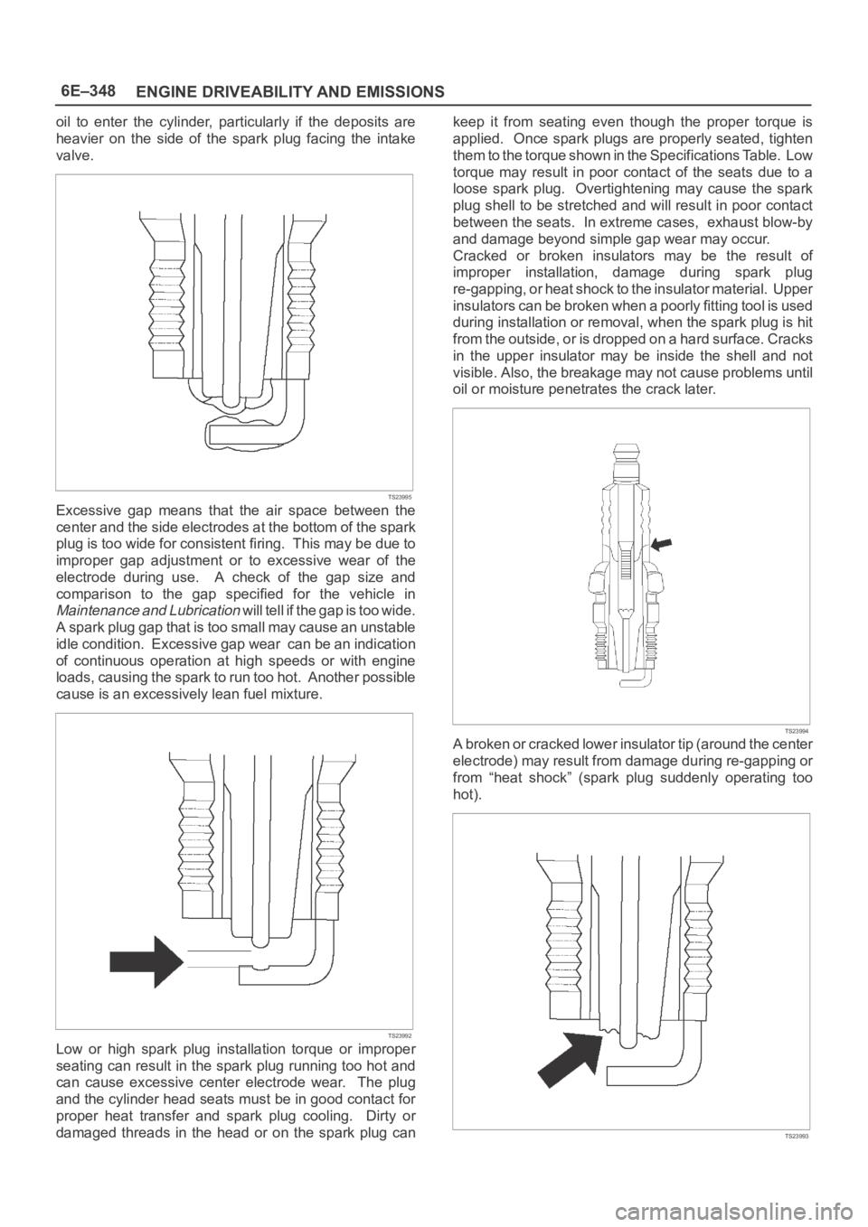
Excessive gap means that the air space between the
center and the side electrodes at the bottom of the spark
plug is too wide for consistent firing. This may be due to
improper gap adjustment or to excessive wear of the
electrode during use. A check of the gap size and
comparison to the gap specified for the vehicle in
Maintenance and Lubrication will tell if the gap is too wide.
A spark plug gap that is too small may cause an unstable
idle condition. Excessive gap wear can be an indication
of continuous operation at high speeds or with engine
loads, causing the spark to run too hot. Another possible
cause is an excessively lean fuel mixture.
TS23992
Low or high spark plug installation torque or improper
seating can result in the spark plug running too hot and
can cause excessive center electrode wear. The plug
and the cylinder head seats must be in good contact for
proper heat transfer and spark plug cooling. Dirty or
damaged threads in the head or on the spark plug cankeep it from seating even though the proper torque is
applied. Once spark plugs are properly seated, tighten
them to the torque shown in the Specifications Table. Low
torque may result in poor contact of the seats due to a
loose spark plug. Overtightening may cause the spark
plug shell to be stretched and will result in poor contact
between the seats. In extreme cases, exhaust blow-by
and damage beyond simple gap wear may occur.
Cracked or broken insulators may be the result of
improper installation, damage during spark plug
re-gapping, or heat shock to the insulator material. Upper
insulators can be broken when a poorly fitting tool is used
during installation or removal, when the spark plug is hit
from the outside, or is dropped on a hard surface. Cracks
in the upper insulator may be inside the shell and not
visible. Also, the breakage may not cause problems until
oil or moisture penetrates the crack later.
TS23994
A broken or cracked lower insulator tip (around the center
electrode) may result from damage during re-gapping or
from “heat shock” (spark plug suddenly operating too
hot).
TS23993
Page 1739 of 6000

6A – 6 ENGINE MECHANICAL
SERVICE STANDARD
Enginemm (in)
Parts Items Service standard Service limit Remarks
Cylinder Head
Va l v e S p r i n g
Va l v e a n d
Valve guide
Camshaft0.075 (0.0030) or less
95.0 (3.740)
45.7 (1.8)
—
241 (54.2)
6.959 – 6.977
(0.27 – 0.272)
6.692 – 6.970
(0.271 – 0.272)
0.023 – 0.056
(0.0009 – 0.0022)
0.03 – 0.063
(0.0011 – 0.0024)
8.0 (0.312)
1.1 (0.0433)
1.2 (0.0472)
1.2 (0.0472)
45°
2.1 (0.0827)
2.1 (0.0827)
0.08 (0.00314)
46.67 (1.8374)
46.77 (1.8413)
29.939 – 29.960
(1.167 – 1.168)
0.02 (0.0008) or less
0.40 – 0.082
(0.0016 – 0.0032)0.50 (0.0197)
—
44.8 (1.765)
1.6 (0.063)
210 (47.22)
6.92 (0.270)
6.90 (0.269)
0.19 (0.0074)
0.20 (0.0079)
—
1.6 (0.0630)
1.1 (0.0433)
1.1 (0.0433)
—
2.6 (0.1024)
2.6 (0.1024)
2.0 (0.00797)
46.57 (1.8335)
46.67 (1.8374)
29.84 (1.1748)
0.10 (0.0039)
0.12 (0.0047)Cannot be
reground Cylinder head lower surface for flatness
Cylinder head height
Free height
Squareness
Spring tension (when assembled) N(lb)
Diameter of Valve stem IN
EX
Valve and valve guide clearance IN
EX
Valve guide upper end height
(Measured from the Cylinder head upper
face)
Valve guide margin
Valve thickness IN
EX
Valve seat contact surface angle
Valve seat contact width IN
EX
End play
Cam lobe height IN
EX
Journal diameter
Runout
Camshaft oil clearance
Page 1742 of 6000

ENGINE MECHANICAL 6A – 9
SERVICING
Servicing refers to general maintenance procedures to
be performed by qualified service personnel.
MODEL IDENTIFICATION
Engine Serial Number
The engine number is stamped on the rear left hand
side of the cylinder body.
AIR CLEANER
Oil Wetted (Viscous) Type Paper Element.
The air cleaner has an oil wetted paper element. No
servicing is required until the replacement interval is
reached.
Never attempt to clean the element, no matter how dirty
it may appear. The element is designed to provide
normal filtering efficiency until it becomes due for
replacement.
Refer to the Item “Service and Maintenance” in the
Owner’s and Driver’s Manual for general service
information.
LUBRICATING SYSTEM
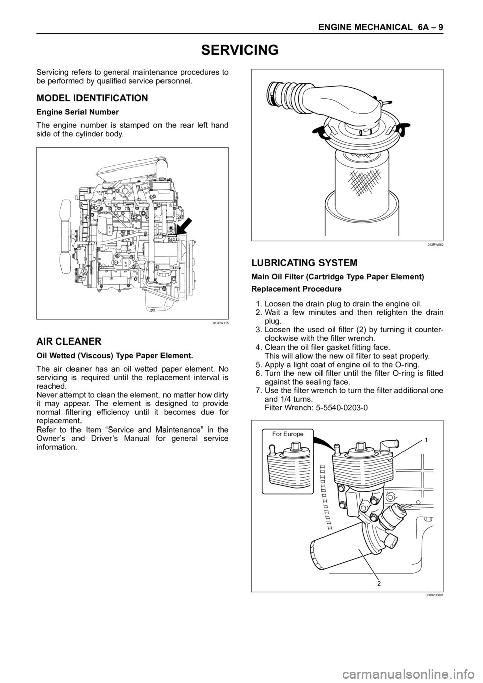
Main Oil Filter (Cartridge Type Paper Element)
Replacement Procedure
1. Loosen the drain plug to drain the engine oil.
2. Wait a few minutes and then retighten the drain
plug.
3. Loosen the used oil filter (2) by turning it counter-
clockwise with the filter wrench.
4. Clean the oil filer gasket fitting face.
This will allow the new oil filter to seat properly.
5. Apply a light coat of engine oil to the O-ring.
6. Turn the new oil filter until the filter O-ring is fitted
against the sealing face.
7. Use the filter wrench to turn the filter additional one
and 1/4 turns.
Filter Wrench: 5-5540-0203-0
012RW115
012RW062
For Europe1
2
050R200001
Page 1743 of 6000

6A – 10 ENGINE MECHANICAL
8. Check the engine oil level and replenish to the
specified level if required.
9. Start the engine and check for oil leakage from the
main oil filter.
FUEL SYSTEM
Fuel filter
Replacement Procedure
1. Loosen the used fuel filter by turning it
counterclockwise with the filter wrench.
Filter Wrench : 5-8840-0203-0
2. Clean the filter cover fitting faces.
This will allow the new fuel filter to seat properly.
3. Apply a light coat of engine oil to the O-ring.
4. Turn the fuel filter until the sealing face comes in
contact with the O-ring.
5. Turn the fuel filter with a filter wrench 2/3 of a turn
until sealed.
Filter Wrench: 5-8840-0203-0Legend
(1) Priming pump
6. Operate the priming pump until the air is discharged
completely from fuel system.
NOTE: The use of an Isuzu genuine fuel filter is
strongly recommended.
COOLING SYSTEM
Coolant Level
Check the coolant level and replenish the radiator
reserve tank as necessary.
If the coolant level falls below the “‘MIN” line, carefully
check the cooling system for leakage. Then add
enough coolant to bring the level up to the “MAX” line.
NOTE: Do not overfill the reserve tank.
012RW112
012RW078
1
012RW111
012RW080