charging OPEL FRONTERA 1998 User Guide
[x] Cancel search | Manufacturer: OPEL, Model Year: 1998, Model line: FRONTERA, Model: OPEL FRONTERA 1998Pages: 6000, PDF Size: 97 MB
Page 1093 of 6000
6D3–2STARTING AND CHARGING SYSTEM
Starting System
General Description
Cranking Circuit
The cranking system consists of a battery, starter, starter
switch, starter relay, etc. These main components are
connected.
Starter
The cranking system employs a magnetic type reduction
starter in which the motor shaft is also used as a pinion
shaft. When the starter switch is turned on, the contacts of
magnetic switch are closed, and the armature rotates. At
the same time, the plunger is attracted, and the pinion is
pushed forward by the shift lever to mesh with the ring
gear.
Then, the ring gear runs to start the engine. When the
engine starts and the starter switch is turned off, the
plunger returns, the pinion is disengaged from the ring
gear, and the armature stops rotation. When the engine
speed is higher than the pinion, the pinion idles, so that
the armature is not driven.
Page 1094 of 6000

6D3–3 STARTING AND CHARGING SYSTEM
C06RW005
Page 1095 of 6000
6D3–4STARTING AND CHARGING SYSTEM
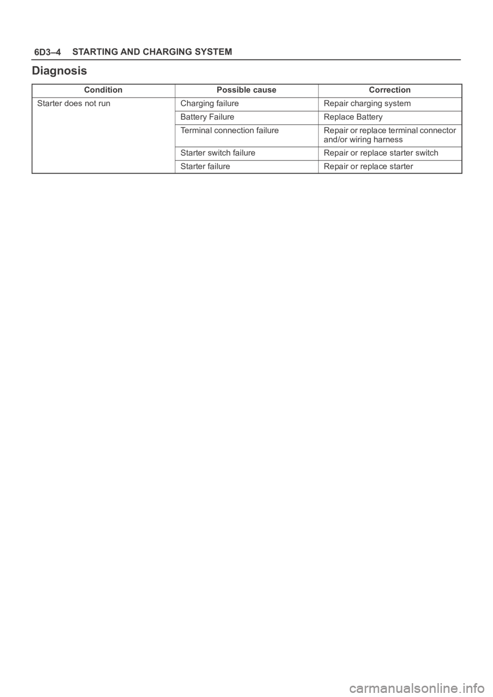
Diagnosis
ConditionPossible causeCorrection
Starter does not runCharging failureRepair charging system
Battery FailureReplace Battery
Terminal connection failureRepair or replace terminal connector
and/or wiring harness
Starter switch failureRepair or replace starter switch
Starter failureRepair or replace starter
Page 1096 of 6000
6D3–5 STARTING AND CHARGING SYSTEM
Starter
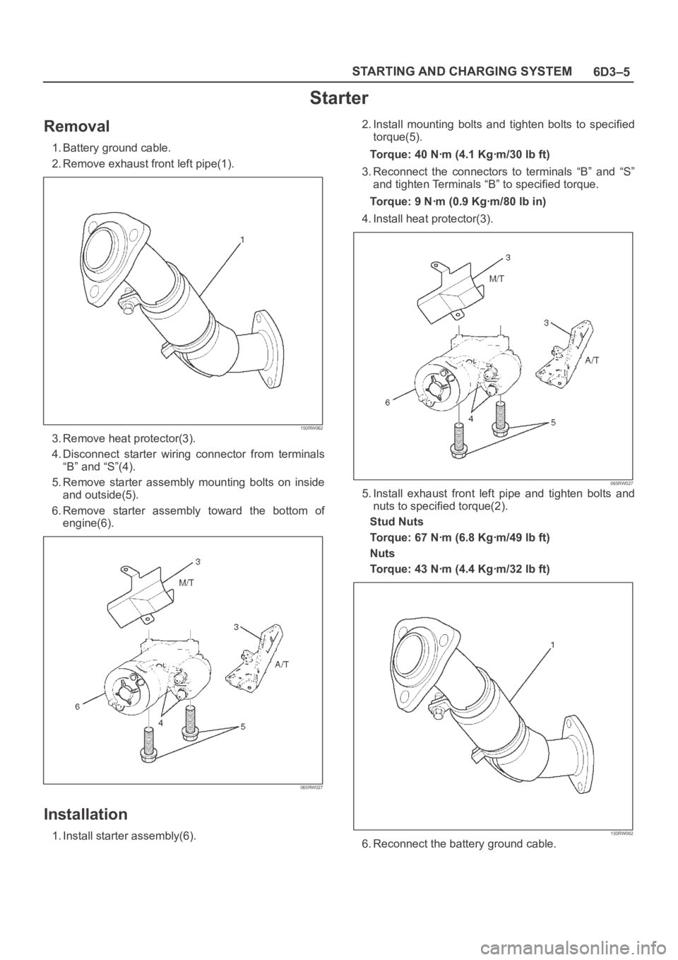
Removal
1. Battery ground cable.
2. Remove exhaust front left pipe(1).
150RW062
3. Remove heat protector(3).
4. Disconnect starter wiring connector from terminals
“B” and “S”(4).
5. Remove starter assembly mounting bolts on inside
and outside(5).
6. Remove starter assembly toward the bottom of
engine(6).
065RW027
Installation
1. Install starter assembly(6).2. Install mounting bolts and tighten bolts to specified
torque(5).
Torque: 40 Nꞏm (4.1 Kgꞏm/30 lb ft)
3. Reconnect the connectors to terminals “B” and “S”
and tighten Terminals “B” to specified torque.
Torque: 9 Nꞏm (0.9 Kgꞏm/80 lb in)
4. Install heat protector(3).
065RW027
5. Install exhaust front left pipe and tighten bolts and
nuts to specified torque(2).
Stud Nuts
Torque: 67 Nꞏm (6.8 Kgꞏm/49 lb ft)
Nuts
Torque: 43 Nꞏm (4.4 Kgꞏm/32 lb ft)
150RW062
6. Reconnect the battery ground cable.
Page 1097 of 6000

6D3–6STARTING AND CHARGING SYSTEM
Disassembled View
065RW002
Legend
(1) Bolt (2 pcs)
(2) Ball Bearing
(3) Pinion
(4) Shift Lever
(5) Dust Cover
(6) Torsion Spring
(7) Dust Cover
(8) Magnetic Switch
(9) Nut
(10) Gear Case
(11) Bearing Cover
(12) E–Ring
(13) Thrust Washer (2)(14) Center Bracket
(15) Pinion Shaft
(16) Planet Gear (3)
(17) Internal Gear
(18) Center Bracket (A)
(19) Yoke Assembly
(20) Armature
(21) Brush
(22) Brush Holder
(23) Thrust Washer
(24) Rear Cover
(25) Screw (2 pcs)
(26) Through Bolt (2 pcs)
Page 1098 of 6000

6D3–7 STARTING AND CHARGING SYSTEM
Disassembly
1. Loosen the nut(1) on terminal “M” of magnetic switch
and disconnect the connector cable.
2. Remove bolt (2 pcs) (2).
065RW003
3. Remove magnetic switch(5).
4. Remove dust cover(4).
5. Remove torsion spring bolts, then the magnetic
switch assembly.
6. Remove torsion spring(3) from magnetic switch
assembly(5).
065RW004
7. Remove screw (2 pcs) (8).
8. Remove through bolt (2 pcs) (7).9. Remove screws and through bolts, then the rear
cover(9) then remove thrust washer(10).
10. Remove brush holder(6).
065RW005
11. Raise a brush spring to detach brushes (4 pcs) from
the commutator face and pull off the brush holder(12)
and brush(11).
065RW006
12. Remove yoke assembly(14).
13. Remove armature(15).
14. Pull off the yoke assembly, then remove armature,
washer and center bracket.(A) (13).
Page 1099 of 6000

6D3–8STARTING AND CHARGING SYSTEM
NOTE: In disassembling the yoke assembly, hold the
armature and pull off slowly the yoke assembly. Because
of strong magnetic force, avoid placing a metallic part
near armature.
065RW007
15. Remove dust cover(17).
16. Remove a dust cover and shift lever(16) from the gear
case.
065RW008
17. Remove ball bearing(19).
18. Remove bearing cover(20).
19. Remove a ball bearing and bearing cover from the
gear case(18).
065RW021
20. Internal gear(21).
21. Remove internal gear and planet gear(3) (22).
065RW009
Page 1100 of 6000

6D3–9 STARTING AND CHARGING SYSTEM
22. Remove an E–ring(23) from the pinion shaft using a
flat blade screwdriver.
065RW010
23. Holding the pinion shaft, push pinion toward the
center bracket. and turn the pinion clockwise or
counterclockwise by one tooth of spline, then pull off
the pinion.
24. Remove thrust washer(24).
25. Remove center bracket
26. Remove pinion shaft.
065RW011
Inspection and Repair
Repair or replace necessary parts if extreme wear or
damage is found during inspection.
Armature
Measure the outer diameter of commutator, and replace
with a new one if it is out of the limit.
Standard: 33.0 mm (1.30 in)
Limit: 32.0 mm (1.26 in)
065RS014Check for continuity between commutator and segment.
Replace commutator if there is no continuity (i.e.,
disconnected).
065RS015
Page 1101 of 6000
6D3–10STARTING AND CHARGING SYSTEM
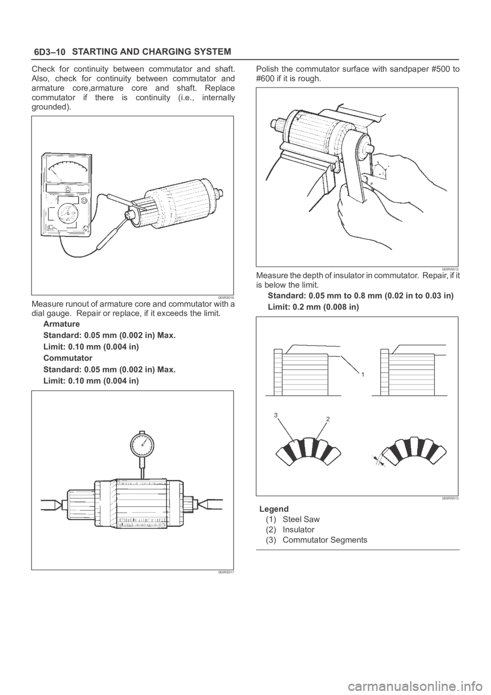
Check for continuity between commutator and shaft.
Also, check for continuity between commutator and
armature core,armature core and shaft. Replace
commutator if there is continuity (i.e., internally
grounded).
065RS016Measure runout of armature core and commutator with a
dial gauge. Repair or replace, if it exceeds the limit.
Armature
Standard: 0.05 mm (0.002 in) Max.
Limit: 0.10 mm (0.004 in)
Commutator
Standard: 0.05 mm (0.002 in) Max.
Limit: 0.10 mm (0.004 in)
065RS017
Polish the commutator surface with sandpaper #500 to
#600 if it is rough.
065RW012Measure the depth of insulator in commutator. Repair, if it
is below the limit.
Standard: 0.05 mm to 0.8 mm (0.02 in to 0.03 in)
Limit: 0.2 mm (0.008 in)
065RW013
Legend
(1) Steel Saw
(2) Insulator
(3) Commutator Segments
Page 1102 of 6000
6D3–11 STARTING AND CHARGING SYSTEM
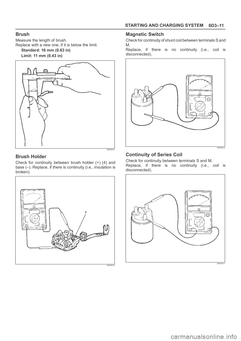
Brush
Measure the length of brush.
Replace with a new one, if it is below the limit.
Standard: 16 mm (0.63 in)
Limit: 11 mm (0.43 in)
065RW014
Brush Holder
Check for continuity between brush holder (+) (4) and
base (–). Replace, if there is continuity (i.e., insulation is
broken).
065RW015
Magnetic Switch
Check for continuity of shunt coil between terminals S and
M.
Replace, if there is no continuity (i.e., coil is
disconnected).
065RW016
Continuity of Series Coil
Check for continuity between terminals S and M.
Replace, if there is no continuity (i.e., coil is
disconnected).
065RW017