charging OPEL FRONTERA 1998 Owner's Guide
[x] Cancel search | Manufacturer: OPEL, Model Year: 1998, Model line: FRONTERA, Model: OPEL FRONTERA 1998Pages: 6000, PDF Size: 97 MB
Page 1113 of 6000
6D3–22STARTING AND CHARGING SYSTEM
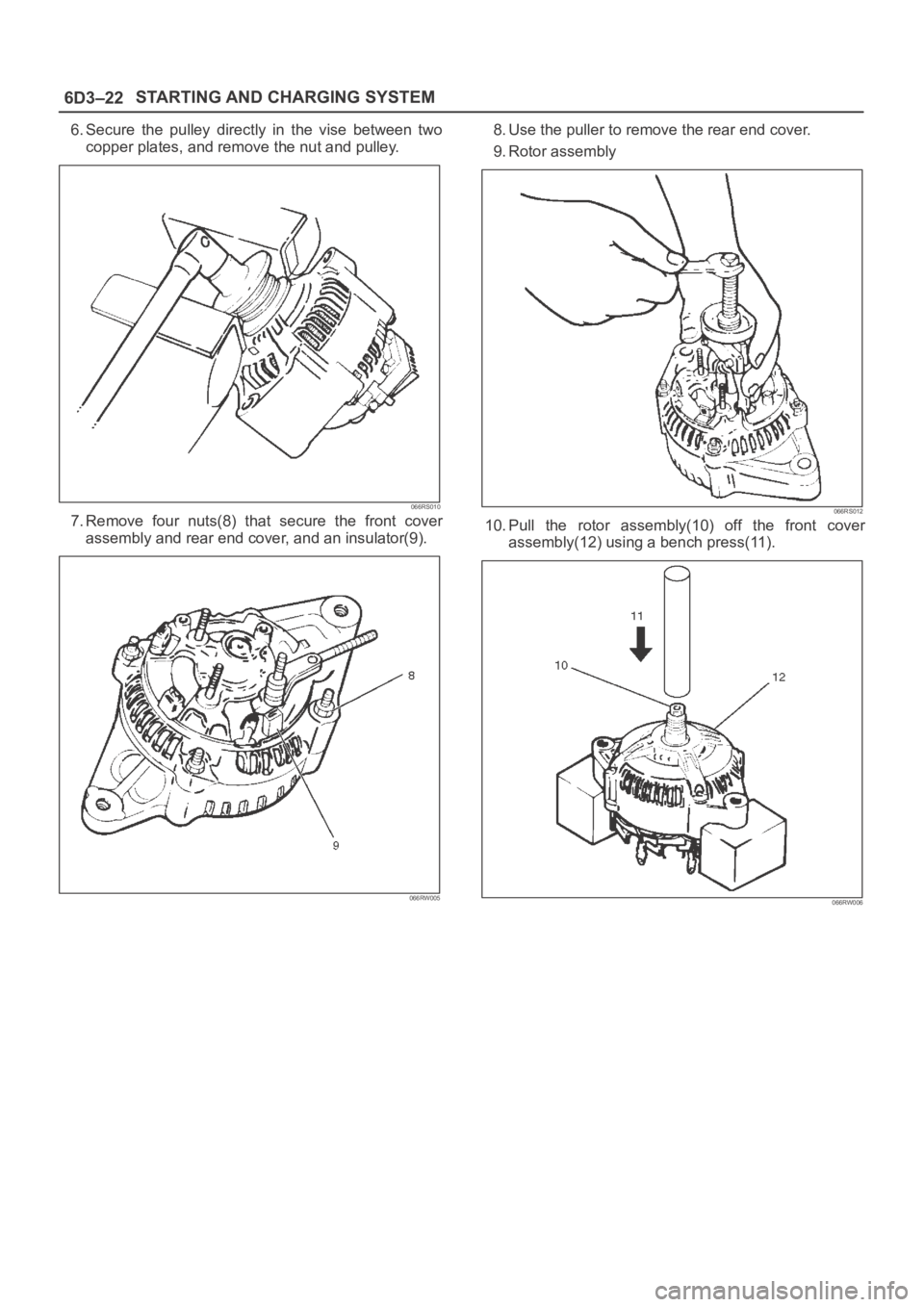
6. Secure the pulley directly in the vise between two
copper plates, and remove the nut and pulley.
066RS010
7. Remove four nuts(8) that secure the front cover
assembly and rear end cover, and an insulator(9).
066RW005
8. Use the puller to remove the rear end cover.
9. Rotor assembly
066RS012
10. Pull the rotor assembly(10) off the front cover
assembly(12) using a bench press(11).
066RW006
Page 1114 of 6000
6D3–23 STARTING AND CHARGING SYSTEM
Inspection and Repair
Repair or replace necessary parts if extreme wear or
damage is found during inspection.
Rotor Assembly
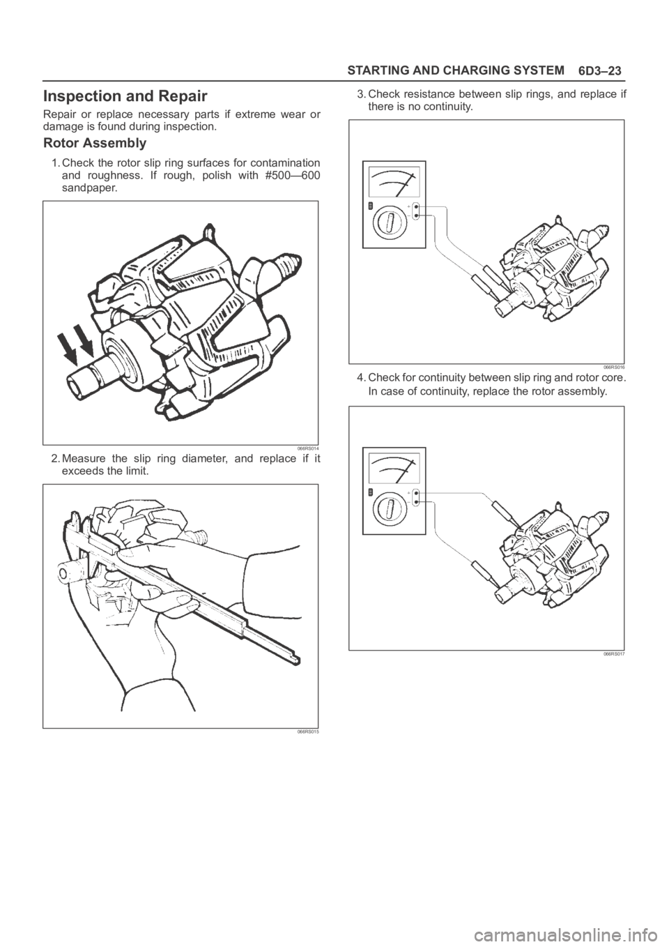
1. Check the rotor slip ring surfaces for contamination
and roughness. If rough, polish with #500—600
sandpaper.
066RS014
2. Measure the slip ring diameter, and replace if it
exceeds the limit.
066RS015
3. Check resistance between slip rings, and replace if
there is no continuity.
066RS016
4. Check for continuity between slip ring and rotor core.
In case of continuity, replace the rotor assembly.
066RS017
Page 1115 of 6000
6D3–24STARTING AND CHARGING SYSTEM
Stator Coil
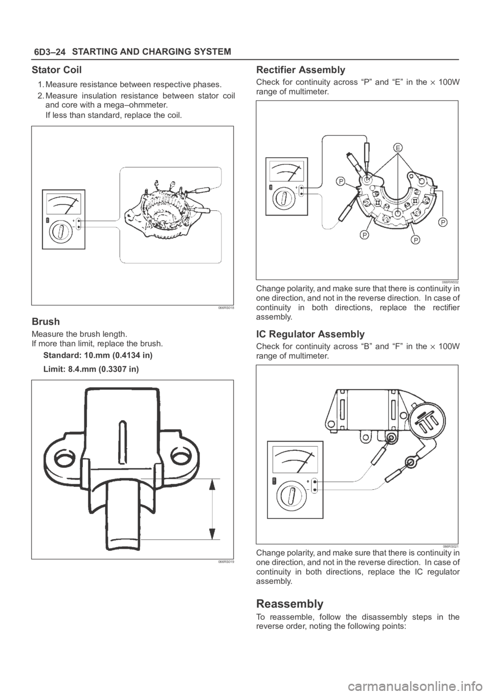
1. Measure resistance between respective phases.
2. Measure insulation resistance between stator coil
and core with a mega–ohmmeter.
If less than standard, replace the coil.
066RS018
Brush
Measure the brush length.
If more than limit, replace the brush.
Standard: 10.mm (0.4134 in)
Limit: 8.4.mm (0.3307 in)
066RS019
Rectifier Assembly
Check for continuity across “P” and “E” in the 100W
range of multimeter.
066RW002Change polarity, and make sure that there is continuity in
one direction, and not in the reverse direction. In case of
continuity in both directions, replace the rectifier
assembly.
IC Regulator Assembly
Check for continuity across “B” and “F” in the 100W
range of multimeter.
066RS021Change polarity, and make sure that there is continuity in
one direction, and not in the reverse direction. In case of
continuity in both directions, replace the IC regulator
assembly.
Reassembly
To reassemble, follow the disassembly steps in the
reverse order, noting the following points:
Page 1116 of 6000
6D3–25 STARTING AND CHARGING SYSTEM
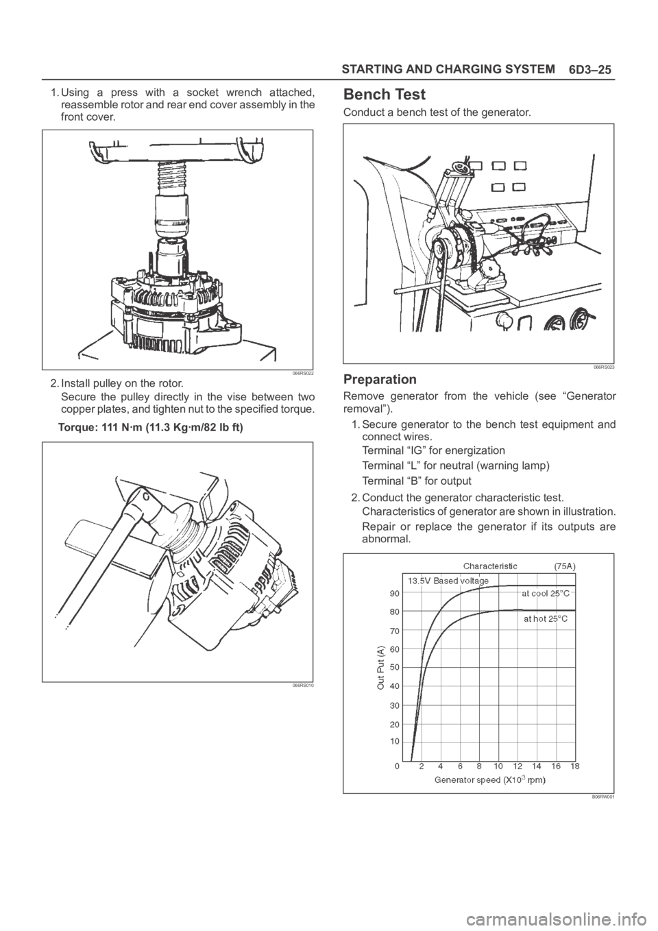
1. Using a press with a socket wrench attached,
reassemble rotor and rear end cover assembly in the
front cover.
066RS022
2. Install pulley on the rotor.
Secure the pulley directly in the vise between two
copper plates, and tighten nut to the specified torque.
Torque: 111 Nꞏm (11.3 Kgꞏm/82 lb ft)
066RS010
Bench Test
Conduct a bench test of the generator.
066RS023
Preparation
Remove generator from the vehicle (see “Generator
removal”).
1. Secure generator to the bench test equipment and
connect wires.
Terminal “IG” for energization
Terminal “L” for neutral (warning lamp)
Terminal “B” for output
2. Conduct the generator characteristic test.
Characteristics of generator are shown in illustration.
Repair or replace the generator if its outputs are
abnormal.
B06RW001
Page 1117 of 6000
6D3–26STARTING AND CHARGING SYSTEM
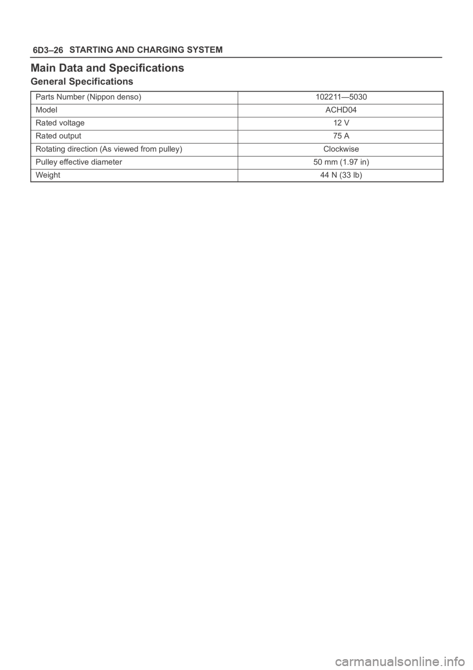
Main Data and Specifications
General Specifications
Parts Number (Nippon denso)102211—5030
ModelACHD04
Rated voltage12 V
Rated output75 A
Rotating direction (As viewed from pulley)Clockwise
Pulley effective diameter50 mm (1.97 in)
Weight44 N (33 lb)
Page 1415 of 6000
6E–298
ENGINE DRIVEABILITY AND EMISSIONS
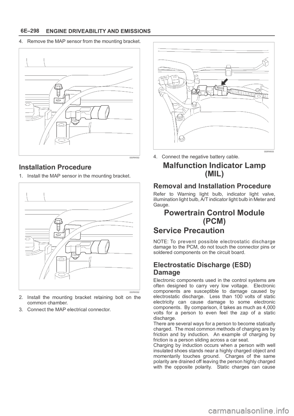
4. Remove the MAP sensor from the mounting bracket.
055RW002
Installation Procedure
1. Install the MAP sensor in the mounting bracket.
055RW002
2. Install the mounting bracket retaining bolt on the
common chamber.
3. Connect the MAP electrical connector.
055RW005
4. Connect the negative battery cable.
Malfunction Indicator Lamp
(MIL)
Removal and Installation Procedure
Refer to Warning light bulb, indicator light valve,
illumination light bulb, A/T indicator light bulb in Meter and
Gauge.
Powertrain Control Module
(PCM)
Service Precaution
NOTE: To prevent possible electrostatic discharge
damage to the PCM, do not touch the connector pins or
soldered components on the circuit board.
Electrostatic Discharge (ESD)
Damage
Electronic components used in the control systems are
often designed to carry very low voltage. Electronic
components are susceptible to damage caused by
electrostatic discharge. Less than 100 volts of static
electricity can cause damage to some electronic
components. By comparison, it takes as much as 4,000
volts for a person to even feel the zap of a static
discharge.
There are several ways for a person to become statically
charged. The most common methods of charging are by
friction and by induction. An example of charging by
friction is a person sliding across a car seat.
Charging by induction occurs when a person with well
insulated shoes stands near a highly charged object and
momentarily touches ground. Charges of the same
polarity are drained off leaving the person highly charged
with the opposite polarity. Static charges can cause
Page 1458 of 6000
6E–341 ENGINE DRIVEABILITY AND EMISSIONS
this is done, if the problem still exists, it may be diagnosed
in the normal manner.
Electrostatic Discharge Damage
Electronic components used in the PCM are often
designed to carry very low voltage. Electronic
components are susceptible to damage caused by
electrostatic discharge. Less than 100 volts of static
electricity can cause damage to some electronic
components. By comparison, it takes as much as 4000
volts for a person to feel even the zap of a static
discharge.
TS23793
There are several ways for a person to become statically
charged. The most common methods of charging are by
friction and induction.
An example of charging by friction is a person sliding
across a vehicle seat.
Charge by induction occurs when a person with well
insulated shoes stands near a highly charged object
and momentary touches ground. Charges of the
same polarity are drained off leaving the person
highly charged with the opposite polarity. Static
charges can cause damage, therefore it is important
to use care when handling and testing electronic
components.
NOTE: To prevent possible electrostatic discharge
damage, follow these guidelines:
Do not touch the PCM connector pins or soldered
components on the PCM circuit board.
Do not touch the knock sensor module component
leads.
Do not open the replacement part package until the
part is ready to be installed.
Before removing the part from the package, ground
the package to a known good ground on the vehicle.
If the part has been handled while sliding across the
seat, while sitting down from a standing position, or
while walking a distance, touch a known good ground
before installing the part.
Upshift Lamp
Refer to Manual Transmission.
General Description (Air Induction)
Air Induction System
The air induction system filters contaminants from the
outside air, and directs the progress of the air as it is
drawn into the engine. A remote-mounted air cleaner
prevents dirt and debris in the air from entering the
engine. The air duct assembly routes filtered air to the
throttle body. Air enters the engine by to following steps:
1. Through the throttle body.
2. Into the common chamber.
3. Through the cylinder head intake ports.
4. Into the cylinders.
055RV010
General Description (Fuel Metering)
Acceleration Mode
The PCM provides extra fuel when it detects a rapid
increase in the throttle position and the air flow.
Accelerator Controls
The accelerator control system is a cable-type system
with specific linkage adjustments.
Refer to
Cable Adjustment.
Battery Voltage Correction Mode
When battery voltage is low, the PCM will compensate for
the weak spark by increasing the following:
The amount of fuel delivered.
The idle RPM.
Ignition dwell time.
CMP Signal
The PCM uses this signal to determine the position of the
number 1 piston during its power stroke, allowing the
Page 1738 of 6000

ENGINE MECHANICAL 6A – 5
Charging System
Model (HITACHI) LR190-750B LR1100 – 731
Rated voltage V 12
Rated output A 90 100
Rotation direction
Clockwise
(As viewed from pulled)
Pulley effective diameter mm (in) 69 (2.72)
Weight N (kg/lb) 52 (5.3/11.7)
Page 1868 of 6000

ENGINE ELECTRICAL 6D – 1
ENGINE ELECTRICAL
CONTENTS
Battery . . . . . . . . . . . . . . . . . . . . . . . . . . . . 6D–1
General Description . . . . . . . . . . . . . . . . 6D–1
Diagnosis . . . . . . . . . . . . . . . . . . . . . . . . 6D–1
On Vehicle Service . . . . . . . . . . . . . . . . . 6D–3
Main Data and Specification . . . . . . . . . . 6D–4
Starting System . . . . . . . . . . . . . . . . . . . . . 6D–5
General Description . . . . . . . . . . . . . . . . 6D–5
On Vehicle Service . . . . . . . . . . . . . . . . . 6D–7
Starter . . . . . . . . . . . . . . . . . . . . . . . . . . 6D–7
Unit Repair . . . . . . . . . . . . . . . . . . . . . . . 6D–8Charging System . . . . . . . . . . . . . . . . . . . . 6D–15
General Description . . . . . . . . . . . . . . . . 6D–15
Diagnosis . . . . . . . . . . . . . . . . . . . . . . . . 6D–16
Unit Repair . . . . . . . . . . . . . . . . . . . . . . . 6D–17
Main Data and Specification . . . . . . . . . . 6D–22
QOS4 Preheating System . . . . . . . . . . . . . . 6D–23
General Description . . . . . . . . . . . . . . . . 6D–23
System Diagram . . . . . . . . . . . . . . . . . . . 6D–23
Inspection of QOS4 System Operation . . 6D–24
BATTERY
GENERAL DESCRIPTION
DIAGNOSIS
There are six battery fluid caps at the top of the battery.
These are covered by a paper label.
The battery is completely sealed except for the six
small vent holes at the side. These vent holes permit
the escape of small amounts of gas generated by the
battery.
This type of battery has the following advantages over
conventional batteries:1. There is no need to add water during the entire
service life of the battery.
2. The battery protects itself against overcharging.
The battery will refuse to accept an excessive
charge.
(A conventional battery will accept an excessive
charge, resulting in gassing and loss of battery
fluid.)
3. The battery is much less vulnerable to self-
discharge than a conventional type battery.
1. VISUAL INSPECTION (Step 1)
Inspect the battery for obvious physical damage, such
as a cracked or broken case, which would permit
electrolyte loss.
Replace the battery if obvious physical damage is
discovered during inspection.
Check for any other physical damage and correct it as
necessary. If not, proceed to Step 2.
2. HYDROMETER CHECK (Step 2)
There is a built-in hydrometer (Charge test indicator) at
the top of the battery. It is designed to be used during
diagnostic procedures.
Before trying to read the hydrometer, carefully clean the
upper battery surface.
If your work area is poorly lit, additional light may be
necessary to read the hydrometer.
a. BLUE RING OR DOT VISIBLE – Go to Step 4.
b. BLUE RING OR DOT NOT VISIBLE – Go to
Step 3.3. FLUID LEVEL CHECK (Step 3)
The fluid level should be between the upper level line
and lower level line on side of the battery.
a. CORRECT FLUID LEVEL – Charge the battery.
b. BELOW LOWER LEVEL – Replace battery.
4. VOLTAGE CHECK (Step 4)
(1) Put voltmeter test leads to battery terminals.
a. VOLTAGE IS 12.4V OR ABOVE – Go to Step 5.
b. VOLTAGE IS UNDER 12.4V – Go to procedure
(2) below.
(2) Determine fast charge amperage from
specification. (See Main Data and Specifications in
this section.)
Fast charge battery for 30 minutes at amperage
rate no higher than specified value.
Take voltage and amperage readings after charge.
a. VOLTAGE IS ABOVE 16V AT BELOW 1/3 OF
AMPERAGE RATE – Replace battery.
Page 1869 of 6000

6D – 2 ENGINE ELECTRICAL
b. VOLTAGE IS ABOVE 16V AT ABOVE 1/3 OF
AMPERAGE RATE – Drop charging voltage to
15V and charge for 10 – 15 hours.
Then go to Step 5.
c. VOLTAGE IS BETWEEN 12V AND 16V –
Continue charging at the same rate for an
additional 3-1/2 hours. Then go to Step 5.
d. VOLTAGE IS BELOW 12V – Replace battery.
5. LOAD TEST (Step 5)
(1) Connect a voltmeter and a battery load tester
across the battery terminals.
(2) Apply 300 ampere load for 15 seconds to remove
surface charge from the battery.
Remove load.
(3) Wait 15 seconds to let battery recover. Then apply
specified load from specifications (See Main Data
and Specifications in this section).
Read voltage after 15 seconds, then remove load.
a. VOLTAGE DOES NOT DROP BELOW THE
MINIMUM LISTED IN FOLLOWING TABLE –
The battery is good and should be returned to
service.
b. VOLTAGE IS LESS THAN MINIMUM LISTED –
Replace battery.
ESTIMATED
TEMPERATUREMINIMUM
°F °CVOLTAGE
70 21 9.6
60 16 9.5
50 10 9.4
40 4 9.3
30 –1 9.1
20 –7 8.9
10 –12 8.7
0 –18 8.5
The battery temperature must be estimated by feel
and by the temperature the battery has been
exposed to for the preceding few hours.