display OPEL FRONTERA 1998 User Guide
[x] Cancel search | Manufacturer: OPEL, Model Year: 1998, Model line: FRONTERA, Model: OPEL FRONTERA 1998Pages: 6000, PDF Size: 97 MB
Page 599 of 6000

DRIVE LINE CONTROL SYSTEM (TOD) 4B2–28
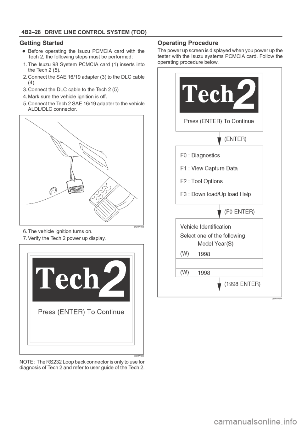
Getting Started
Before operating the Isuzu PCMCIA card with the
Tech 2, the following steps must be performed:
1. The Isuzu 98 System PCMCIA card (1) inserts into
the Tech 2 (5).
2. Connect the SAE 16/19 adapter (3) to the DLC cable
(4).
3. Connect the DLC cable to the Tech 2 (5)
4. Mark sure the vehicle ignition is off.
5. Connect the Tech 2 SAE 16/19 adapter to the vehicle
ALDL/DLC connector.
810RW308
6. The vehicle ignition turns on.
7. Verify the Tech 2 power up display.
060RW009
NOTE: The RS232 Loop back connector is only to use for
diagnosis of Tech 2 and refer to user guide of the Tech 2.
Operating Procedure
The power up screen is displayed when you power up the
tester with the Isuzu systems PCMCIA card. Follow the
operating procedure below.
060RW014
Page 636 of 6000

4B2–65 DRIVE LINE CONTROL SYSTEM (TOD)
Chart C–14H switch circuit wires are broken or the battery is short-circuited.
Function of circuit—
Fail conditionWhen the 4WD SW is 4WD mode.
When the lever is shifted from 4L to HIGH, the 4L mode remains on the indicator and the
TOD mode is displayed without turning off the previous mode.
Indicator lamp status
Transfer position4L <——> Neutral <——> TOD
D04RW062
Page 642 of 6000

4B2–71 DRIVE LINE CONTROL SYSTEM (TOD)
Chart D–14L switch circuit wires are broken or the battery is short-circuited.
Function of circuit—
Fail conditionThe TOD mode is displayed in the neutral position between high and 4L. When the lever
is shifted to the 4L position, the TOD mode is displayed.
Indicator lamp status
Transfer position4LNeutral
D04RW061
Page 644 of 6000

4B2–73 DRIVE LINE CONTROL SYSTEM (TOD)
Chart D–2The 4L switch circuit is short-circuited to GND.
Function of circuit—
Fail conditionThe 4L mode is displayed even in the 2H or TOD.
Indicator lamp status
Transfer positionHIGH (2H or TOD)
D04RW059
Page 653 of 6000

DRIVE LINE CONTROL SYSTEM (TOD) 4B2–82
Chart GThe trouble codes are displayed.
Function of circuit—
Fail condition
Indicator lamp status
Transfer position—
D04RW056
Page 819 of 6000

5A–9 BRAKE CONTROL SYSTEM
Getting Started
Before operating the Isuzu PCMCIA card with the
Tech 2, the following steps must be performed:
1. The Isuzu 98 System PCMCIA card (1) inserts into
the Tech 2 (4).
2. Connect the SAE 16/19 adapter (2) to the DLC cable
(3).
3. Connect the DLC cable to the Tech 2 (4).
4. Make sure the vehicle ignition is off.
5. Connect the Tech 2 SAE 16/19 adapter to the vehicle
DLC connector.
350RV014
6. The vehicle ignition turns on.
7. Power up the Tech 2.8. Verify the Tech 2 power up display.
060RW009
Page 820 of 6000

5A–10
BRAKE CONTROL SYSTEM
Operating Procedure
The power up screen is displayed when you power up the
tester with the Isuzu systems PCMCIA card. Follow the
operating procedure below.
060RW014
060RW020
Page 821 of 6000

5A–11 BRAKE CONTROL SYSTEM
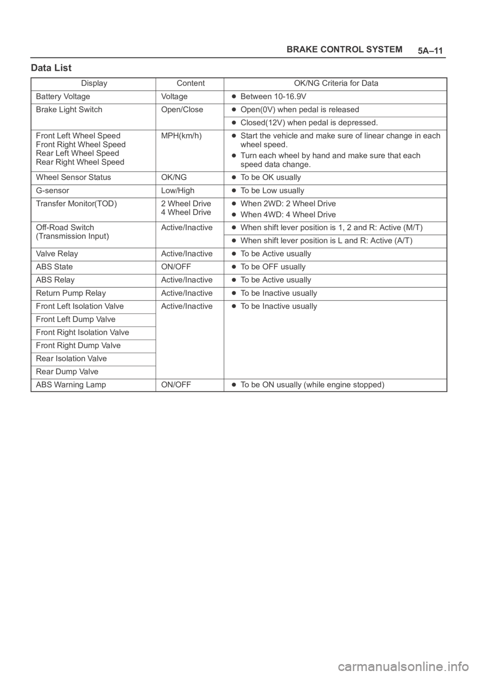
Data List
DisplayContentOK/NG Criteria for Data
Battery VoltageVo l t a g eBetween 10-16.9V
Brake Light SwitchOpen/CloseOpen(0V) when pedal is released
Closed(12V) when pedal is depressed.
Front Left Wheel Speed
Front Right Wheel Speed
Rear Left Wheel Speed
Rear Right Wheel SpeedMPH(km/h)Start the vehicle and make sure of linear change in each
wheel speed.
Turn each wheel by hand and make sure that each
speed data change.
Wheel Sensor StatusOK/NGTo be OK usually
G-sensorLow/HighTo be Low usually
Transfer Monitor(TOD)2 Wheel Drive
4 Wheel DriveWhen 2WD: 2 Wheel Drive
When 4WD: 4 Wheel Drive
Off-Road Switch
(Transmission Input)
Active/InactiveWhen shift lever position is 1, 2 and R: Active (M/T)
(Transmission Input)When shift lever position is L and R: Active (A/T)
Valve RelayActive/InactiveTo be Active usually
ABS StateON/OFFTo be OFF usually
ABS RelayActive/InactiveTo be Active usually
Return Pump RelayActive/InactiveTo be Inactive usually
Front Left Isolation ValveActive/InactiveTo be Inactive usually
Front Left Dump Valve
Front Right Isolation Valve
Front Right Dump Valve
Rear Isolation Valve
Rear Dump Valve
ABS Warning LampON/OFFTo be ON usually (while engine stopped)
Page 846 of 6000

5A–36
BRAKE CONTROL SYSTEM
StepNo Ye s
Action
10Is the input of 4WD controller normal?
Go to Step 11
Replace
controller or
repair harness.
Go to Step 11
11Reconnect all components and ensure all components are
properly mounted.
Was this step finished?Repeat the “Basic
diagnostic flow
chart.”
Go to Step 11
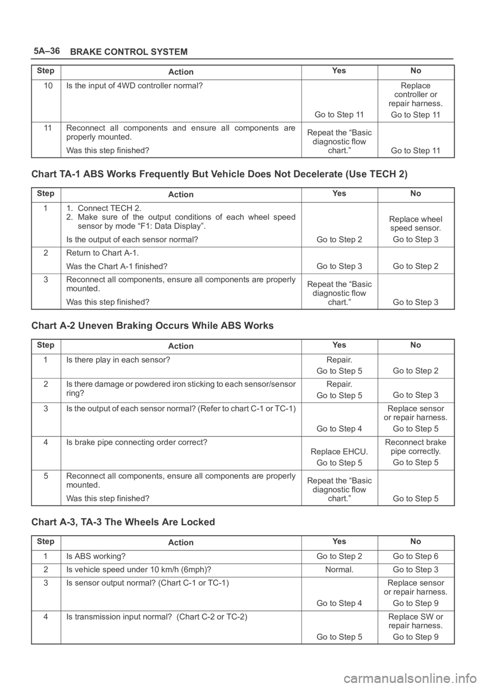
Chart TA-1 ABS Works Frequently But Vehicle Does Not Decelerate (Use TECH 2)
StepActionYe sNo
11. Connect TECH 2.
2. Make sure of the output conditions of each wheel speed
sensor by mode “F1: Data Display”.
Is the output of each sensor normal?
Go to Step 2
Replace wheel
speed sensor.
Go to Step 3
2Return to Chart A-1.
Was the Chart A-1 finished?
Go to Step 3Go to Step 2
3Reconnect all components, ensure all components are properly
mounted.
Was this step finished?Repeat the “Basic
diagnostic flow
chart.”
Go to Step 3
Chart A-2 Uneven Braking Occurs While ABS Works
StepActionYe sNo
1Is there play in each sensor?Repair.
Go to Step 5
Go to Step 2
2Is there damage or powdered iron sticking to each sensor/sensor
ring?Repair.
Go to Step 5
Go to Step 3
3Is the output of each sensor normal? (Refer to chart C-1 or TC-1)
Go to Step 4
Replace sensor
or repair harness.
Go to Step 5
4Is brake pipe connecting order correct?
Replace EHCU.
Go to Step 5
Reconnect brake
pipe correctly.
Go to Step 5
5Reconnect all components, ensure all components are properly
mounted.
Was this step finished?Repeat the “Basic
diagnostic flow
chart.”
Go to Step 5
Chart A-3, TA-3 The Wheels Are Locked
StepActionYe sNo
1Is ABS working?Go to Step 2Go to Step 6
2Is vehicle speed under 10 km/h (6mph)?Normal.Go to Step 3
3Is sensor output normal? (Chart C-1 or TC-1)
Go to Step 4
Replace sensor
or repair harness.
Go to Step 9
4Is transmission input normal? (Chart C-2 or TC-2)
Go to Step 5
Replace SW or
repair harness.
Go to Step 9
Page 850 of 6000

5A–40
BRAKE CONTROL SYSTEM
Diagnosis By “ABS” Warning Light
Illumination Pattern
In the event that there is abnormality in the “ABS” warning
light illumination pattern while the key is in the ON position
or if the warning light is actuated during driving, trouble
should be diagnosed on a illumination pattern basis as
follows:
No.
Condition“ABS” Warning Light Illumination PatternDiagnostic
1Warning light is actu-
ated normallyNormal
2Warning light is not litWarning light lighting circuit
trouble
Go to Chart B-1
3Warning light remains
ONDiagnostic trouble codes are
stored.
Display diagnostic trouble
codes and diagnose on a
code basis according to the
flow charts.
4Warning light is actu-
ated while drivingDiagnostic trouble codes are
stored.
Display diagnostic trouble
codes and diagnose on a
code basis according to the
flow charts.
Diagnostic Trouble Codes (DTCs)
When the warning light in the meter remains ON, the
EHCU stores the fault identification and disables the
ABS.
1. How to display and erase DTCs:
NOTE:
If DTCs are not displayed, harness C-4 connector
terminal 30 and I-10 connector terminal 2 may be
disconnected. Repair the harness and try DTC
display again.
DTCs can be displayed also by TECH 2. Select mode
“F0: Diagnostic Trouble Codes” from Application
Menu.
1. How to start DTC display:
Confirm that the vehicle has come to a complete
stop (with the wheels standing still) and that the
brake pedal is not depressed. (Unless these two
conditions are satisfied, DTC display cannot be
started.)
With IGN OFF, connect #12 terminal with #4
terminal or # 5 terminal (GND) . Then turn IGN ON.