fuse box OPEL FRONTERA 1998 User Guide
[x] Cancel search | Manufacturer: OPEL, Model Year: 1998, Model line: FRONTERA, Model: OPEL FRONTERA 1998Pages: 6000, PDF Size: 97 MB
Page 1148 of 6000
6E–31 ENGINE DRIVEABILITY AND EMISSIONS
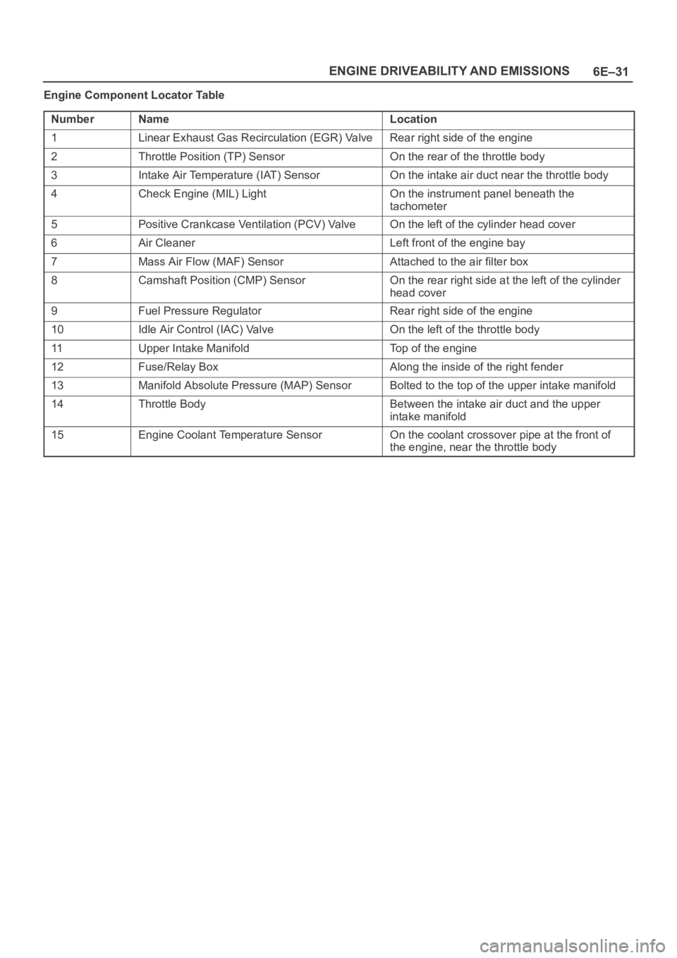
Engine Component Locator Table
Number
NameLocation
1Linear Exhaust Gas Recirculation (EGR) ValveRear right side of the engine
2Throttle Position (TP) SensorOn the rear of the throttle body
3Intake Air Temperature (IAT) SensorOn the intake air duct near the throttle body
4Check Engine (MIL) LightOn the instrument panel beneath the
tachometer
5Positive Crankcase Ventilation (PCV) ValveOn the left of the cylinder head cover
6Air CleanerLeft front of the engine bay
7Mass Air Flow (MAF) SensorAttached to the air filter box
8Camshaft Position (CMP) SensorOn the rear right side at the left of the cylinder
head cover
9Fuel Pressure RegulatorRear right side of the engine
10Idle Air Control (IAC) ValveOn the left of the throttle body
11Upper Intake ManifoldTop of the engine
12Fuse/Relay BoxAlong the inside of the right fender
13Manifold Absolute Pressure (MAP) SensorBolted to the top of the upper intake manifold
14Throttle BodyBetween the intake air duct and the upper
intake manifold
15Engine Coolant Temperature SensorOn the coolant crossover pipe at the front of
the engine, near the throttle body
Page 1173 of 6000
6E–56
ENGINE DRIVEABILITY AND EMISSIONS
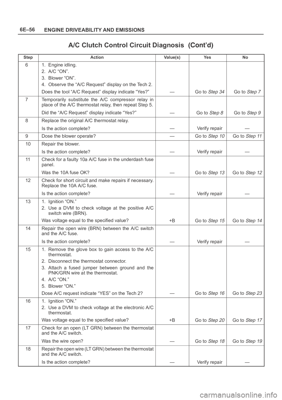
A/C Clutch Control Circuit Diagnosis
StepNo Ye s Va l u e ( s ) Action
61. Engine idling.
2. A/C “ON”.
3. Blower “ON”.
4. Observe the “A/C Request” display on the Tech 2.
Does the tool “A/C Request” display indicate “Yes?”
—Go to Step 34Go to Step 7
7Temporarily substitute the A/C compressor relay in
place of the A/C thermostat relay, then repeat Step 5.
Did the “A/C Request” display indicate “Yes?”
—Go to Step 8Go to Step 9
8Replace the original A/C thermostat relay.
Is the action complete?
—Verify repair—
9Dose the blower operate?—Go to Step 10Go to Step 11
10Repair the blower.
Is the action complete?
—Verify repair—
11Check for a faulty 10a A/C fuse in the underdash fuse
panel.
Was the 10A fuse OK?
—Go to Step 13Go to Step 12
12Check for short circuit and make repairs if necessary.
Replace the 10A A/C fuse.
Is the action complete?
—Verify repair—
131. Ignition “ON.”
2. Use a DVM to check voltage at the positive A/C
switch wire (BRN).
Was voltage equal to the specified value?
+BGo to Step 15Go to Step 14
14Repair the open wire (BRN) between the A/C switch
and the A/C fuse.
Is the action complete?
—Verify repair—
151. Remove the glove box to gain access to the A/C
thermostat.
2. Disconnect the thermostat connector.
3. Attach a fused jumper between ground and the
PNK/GRN wire at the thermostat.
4. A/C “ON.”
5. Blower “ON.”
Dose A/C request indicate “YES” on the Tech 2?
—Go to Step 16Go to Step 23
161. Ignition “ON.”
2. Use a DVM to check voltage at the electronic A/C
thermostat.
Was voltage equal to the specified value?
+BGo to Step 20Go to Step 17
17Check for an open (LT GRN) between the thermostat
and the A/C switch.
Was the wire open?
—Go to Step 18Go to Step 19
18Repair the open wire (LT GRN) between the thermostat
and the A/C switch.
Is the action complete?
—Verify repair—
Page 1198 of 6000
6E–81 ENGINE DRIVEABILITY AND EMISSIONS
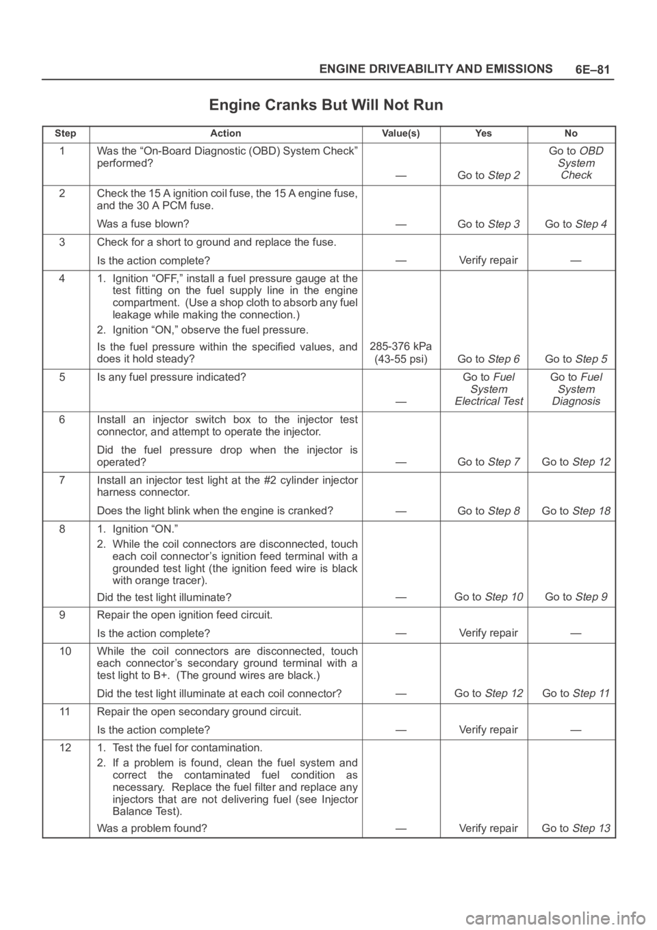
Engine Cranks But Will Not Run
StepActionVa l u e ( s )Ye sNo
1Was the “On-Board Diagnostic (OBD) System Check”
performed?
—Go to Step 2
Go to OBD
System
Check
2Check the 15 A ignition coil fuse, the 15 A engine fuse,
and the 30 A PCM fuse.
Was a fuse blown?
—Go to Step 3Go to Step 4
3Check for a short to ground and replace the fuse.
Is the action complete?
—Verify repair—
41. Ignition “OFF,” install a fuel pressure gauge at the
test fitting on the fuel supply line in the engine
compartment. (Use a shop cloth to absorb any fuel
leakage while making the connection.)
2. Ignition “ON,” observe the fuel pressure.
Is the fuel pressure within the specified values, and
does it hold steady?
285-376 kPa
(43-55 psi)
Go to Step 6Go to Step 5
5Is any fuel pressure indicated?
—
Go to Fuel
System
Electrical TestGo to Fuel
System
Diagnosis
6Install an injector switch box to the injector test
connector, and attempt to operate the injector.
Did the fuel pressure drop when the injector is
operated?
—Go to Step 7Go to Step 12
7Install an injector test light at the #2 cylinder injector
harness connector.
Does the light blink when the engine is cranked?
—Go to Step 8Go to Step 18
81. Ignition “ON.”
2. While the coil connectors are disconnected, touch
each coil connector’s ignition feed terminal with a
grounded test light (the ignition feed wire is black
with orange tracer).
Did the test light illuminate?
—Go to Step 10Go to Step 9
9Repair the open ignition feed circuit.
Is the action complete?
—Verify repair—
10While the coil connectors are disconnected, touch
each connector’s secondary ground terminal with a
test light to B+. (The ground wires are black.)
Did the test light illuminate at each coil connector?
—Go to Step 12Go to Step 11
11Repair the open secondary ground circuit.
Is the action complete?
—Verify repair—
121. Test the fuel for contamination.
2. If a problem is found, clean the fuel system and
correct the contaminated fuel condition as
necessary. Replace the fuel filter and replace any
injectors that are not delivering fuel (see Injector
Balance Test).
Was a problem found?
—Verify repairGo to Step 13
Page 1436 of 6000
6E–319 ENGINE DRIVEABILITY AND EMISSIONS
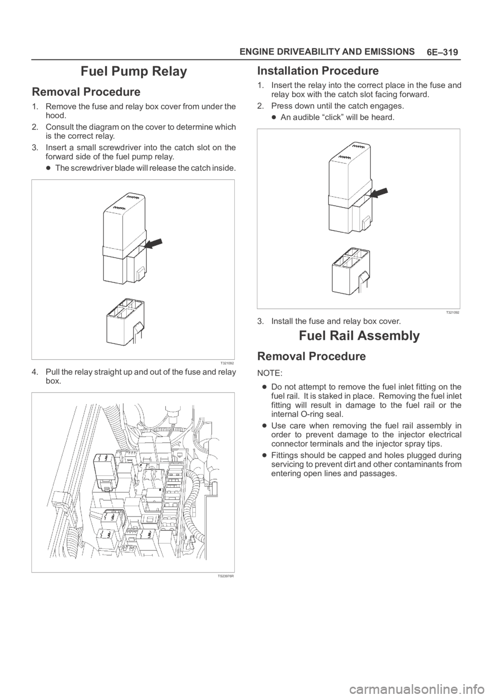
Fuel Pump Relay
Removal Procedure
1. Remove the fuse and relay box cover from under the
hood.
2. Consult the diagram on the cover to determine which
is the correct relay.
3. Insert a small screwdriver into the catch slot on the
forward side of the fuel pump relay.
The screwdriver blade will release the catch inside.
T321092
4. Pull the relay straight up and out of the fuse and relay
box.
TS23976R
Installation Procedure
1. Insert the relay into the correct place in the fuse and
relay box with the catch slot facing forward.
2. Press down until the catch engages.
An audible “click” will be heard.
T321092
3. Install the fuse and relay box cover.
Fuel Rail Assembly
Removal Procedure
NOTE:
Do not attempt to remove the fuel inlet fitting on the
fuel rail. It is staked in place. Removing the fuel inlet
fitting will result in damage to the fuel rail or the
internal O-ring seal.
Use care when removing the fuel rail assembly in
order to prevent damage to the injector electrical
connector terminals and the injector spray tips.
Fittings should be capped and holes plugged during
servicing to prevent dirt and other contaminants from
entering open lines and passages.
Page 1442 of 6000
6E–325 ENGINE DRIVEABILITY AND EMISSIONS
Spark Plug Gap Check
Check the gap of all spark plugs before installation.
Use a round wire feeler gauge to ensure an accurate
check.
Plugs installed with the wrong gap can cause poor
engine performance and excessive emissions.
Installation Procedure
NOTE: The plug must thread smoothly into the cylinder
head and be fully seated. Use a thread chaser if
necessary to clean the threads in the cylinder head.
Cross-threading or failure to fully seat the spark plug can
cause plug overheating, exhaust blow-by gas, or thread
damage. Do not overtighten the spark plugs. Over
tightening can cause aluminum threads to strip.
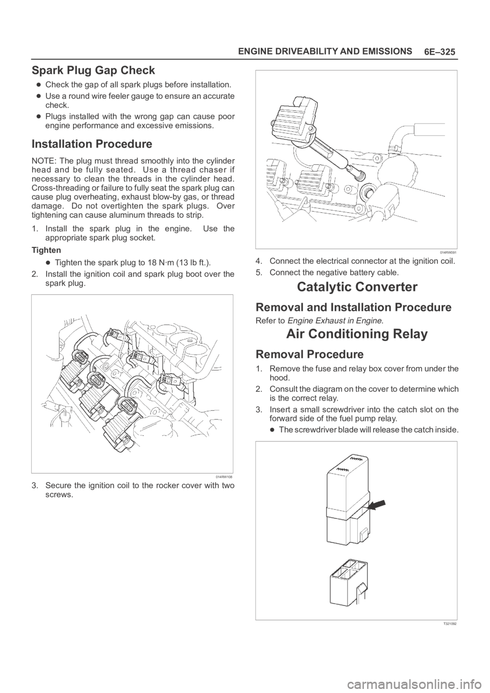
1. Install the spark plug in the engine. Use the
appropriate spark plug socket.
Tighten
Tighten the spark plug to 18 Nꞏm (13 lb ft.).
2. Install the ignition coil and spark plug boot over the
spark plug.
014RW108
3. Secure the ignition coil to the rocker cover with two
screws.
014RW091
4. Connect the electrical connector at the ignition coil.
5. Connect the negative battery cable.
Catalytic Converter
Removal and Installation Procedure
Refer to Engine Exhaust in Engine.
Air Conditioning Relay
Removal Procedure
1. Remove the fuse and relay box cover from under the
hood.
2. Consult the diagram on the cover to determine which
is the correct relay.
3. Insert a small screwdriver into the catch slot on the
forward side of the fuel pump relay.
The screwdriver blade will release the catch inside.
T321092
Page 1443 of 6000
6E–326
ENGINE DRIVEABILITY AND EMISSIONS
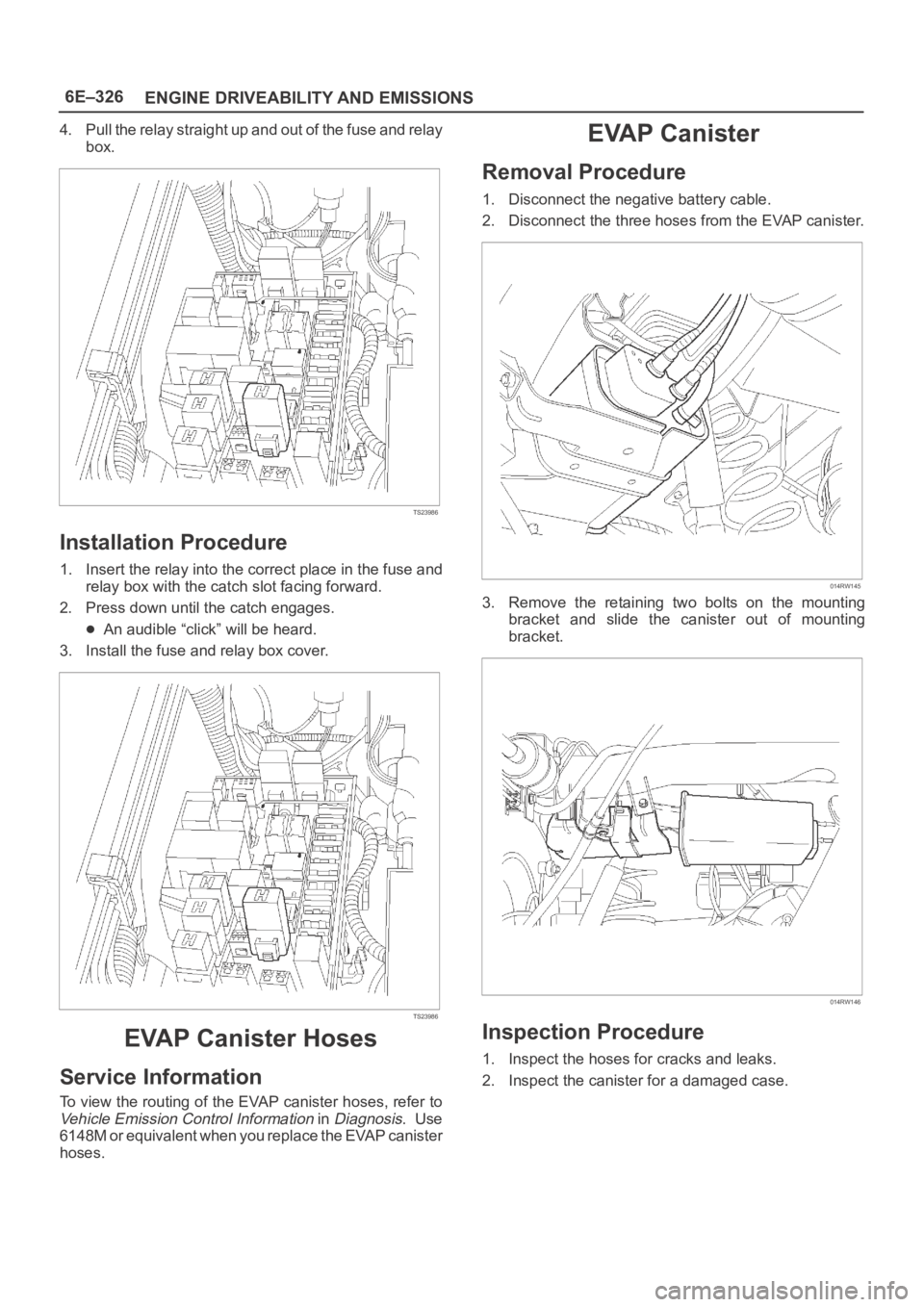
4. Pull the relay straight up and out of the fuse and relay
box.
TS23986
Installation Procedure
1. Insert the relay into the correct place in the fuse and
relay box with the catch slot facing forward.
2. Press down until the catch engages.
An audible “click” will be heard.
3. Install the fuse and relay box cover.
TS23986
EVAP Canister Hoses
Service Information
To view the routing of the EVAP canister hoses, refer to
Vehicle Emission Control Information in Diagnosis. Use
6148M or equivalent when you replace the EVAP canister
hoses.
EVAP Canister
Removal Procedure
1. Disconnect the negative battery cable.
2. Disconnect the three hoses from the EVAP canister.
014RW145
3. Remove the retaining two bolts on the mounting
bracket and slide the canister out of mounting
bracket.
014RW146
Inspection Procedure
1. Inspect the hoses for cracks and leaks.
2. Inspect the canister for a damaged case.
Page 1746 of 6000

ENGINE MECHANICAL 6A – 13
VALVE CLEARANCE ADJUSTMENT
1. Install 2.80 mm valve adjuster (shim) first when
reassembling the engine.
Thickness mark faces down.
2. Measure the valve clearance after installing cam
carrier assy with camshafts.
3. Change the adjuster using a special tool when the
clearance is out of tolerance.
Valve Clearance Adjusting Tool: 5-8840-2590-0
VALVE CLEARANCE (When cold condition)
Inlet 0.15 ± 0.05 mm
Exh 0.25 ± 0.05 mm
COMPRESSION PRESSURE
MEASUREMENT
1. Start the engine and allow it to idle until the coolant
temperature reaches 70 – 80°C (158 – 176°F).
2. Remove the following parts.
Glow plugs
Fuel cut solenoid connector
QOS (Quick-On Start System) fuse in the fuse
box.
3. Set the adapter and compression gauge to the No.
1 cylinder glow plug hole.
Compression Gauge
(with Adapter): 5-8840-2008-0
4. Turn the engine over with the starter motor and take
the compression gauge reading.
Compression Pressure at 200 rpm
Standard: 3040 kPa (31 kg/cm
2/441 psi)
Limit: 2160 kPa (22 kg/cm
2/313 psi)
5. Repeat the procedure (Steps 3 and 4) for the
remaining cylinders.
QUICK-ON START 4 SYSTEM
Quick-On Start System Inspection Procedure
1. Disconnect the ECT-sensor connection around the
thermostat outlet pipe.
2. Turn the starter switch to the “ON” position.
If the Quick-On Start 4 System is operating
properly, the glow relay will make a clicking sound
within seven seconds after the starter switch is
turned on.
3. Measure the glow plug terminal voltage with a
circuit tester immediately after turning the starter
switch to the “ON” position.
Glow Plug Terminal Voltage: approx. 12V
NOTE: Electrical power to the quick-on start system will
be cut after the starter has remained in the “ON”
position for twenty seconds.
Turn the starter switch to the “OFF” position and back
to the “ON” position.
This will reset the Quick-On Start 4 System.
014RW150
Page 2110 of 6000
6E–217 4JX1–TC ENGINE DRIVEABILITY AND EMISSIONS
Throttle Body (TB)
Removal Procedure
1. Disconnect the negative battery cable.
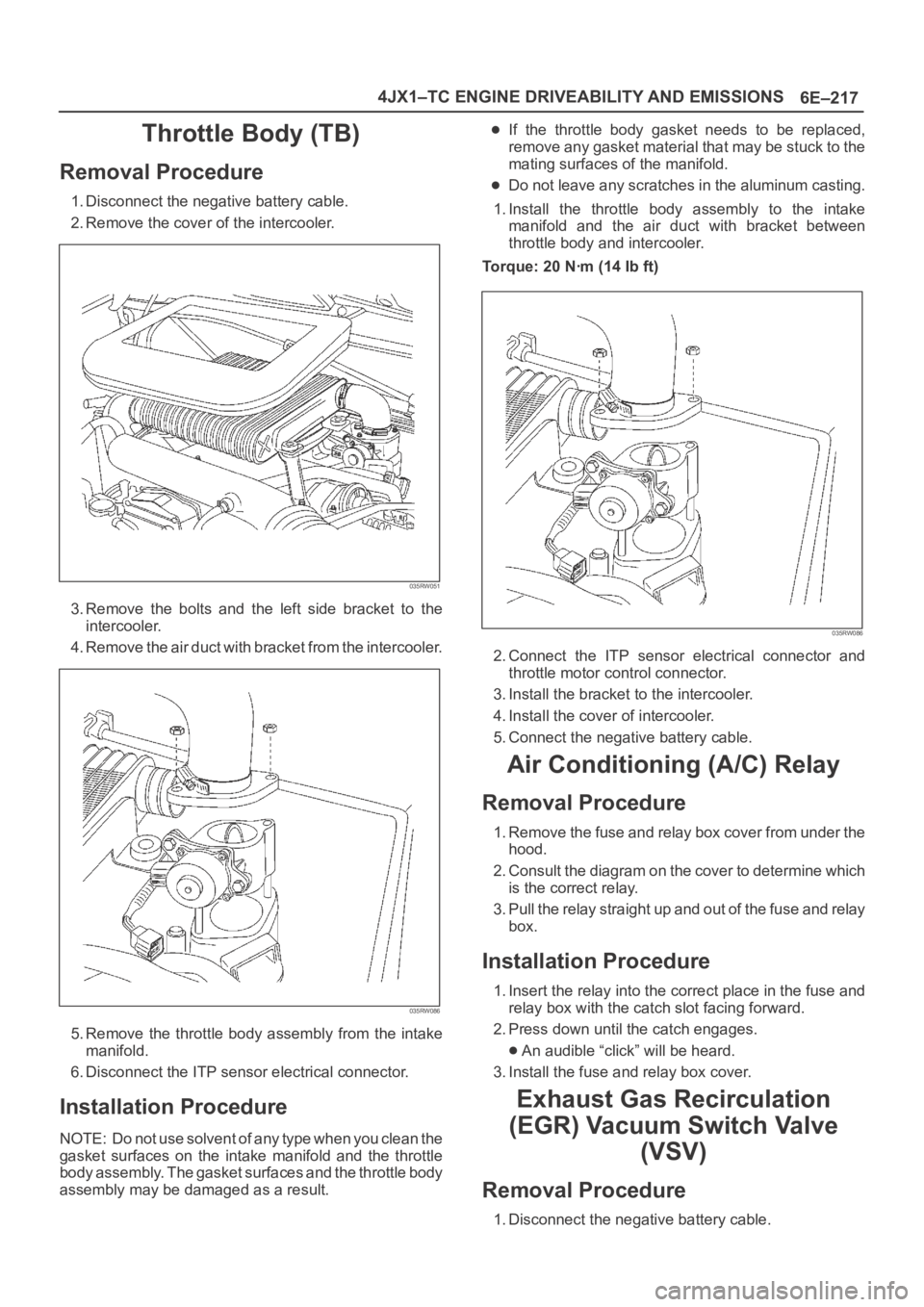
2. Remove the cover of the intercooler.
035RW051
3. Remove the bolts and the left side bracket to the
intercooler.
4 . R e m o v e t h e a i r d u c t w i t h b r a c k e t f r o m t h e i n t e r c o o l e r.
035RW086
5. Remove the throttle body assembly from the intake
manifold.
6. Disconnect the ITP sensor electrical connector.
Installation Procedure
NOTE: Do not use solvent of any type when you clean the
gasket surfaces on the intake manifold and the throttle
body assembly. The gasket surfaces and the throttle body
assembly may be damaged as a result.
If the throttle body gasket needs to be replaced,
remove any gasket material that may be stuck to the
mating surfaces of the manifold.
Do not leave any scratches in the aluminum casting.
1. Install the throttle body assembly to the intake
manifold and the air duct with bracket between
throttle body and intercooler.
Torque: 20 Nꞏm (14 Ib ft)
035RW086
2. Connect the ITP sensor electrical connector and
throttle motor control connector.
3. Install the bracket to the intercooler.
4. Install the cover of intercooler.
5. Connect the negative battery cable.
Air Conditioning (A/C) Relay
Removal Procedure
1. Remove the fuse and relay box cover from under the
hood.
2. Consult the diagram on the cover to determine which
is the correct relay.
3. Pull the relay straight up and out of the fuse and relay
box.
Installation Procedure
1. Insert the relay into the correct place in the fuse and
relay box with the catch slot facing forward.
2. Press down until the catch engages.
An audible “click” will be heard.
3. Install the fuse and relay box cover.
Exhaust Gas Recirculation
(EGR) Vacuum Switch Valve
(VSV)
Removal Procedure
1. Disconnect the negative battery cable.
Page 2617 of 6000
12
D08RWA03
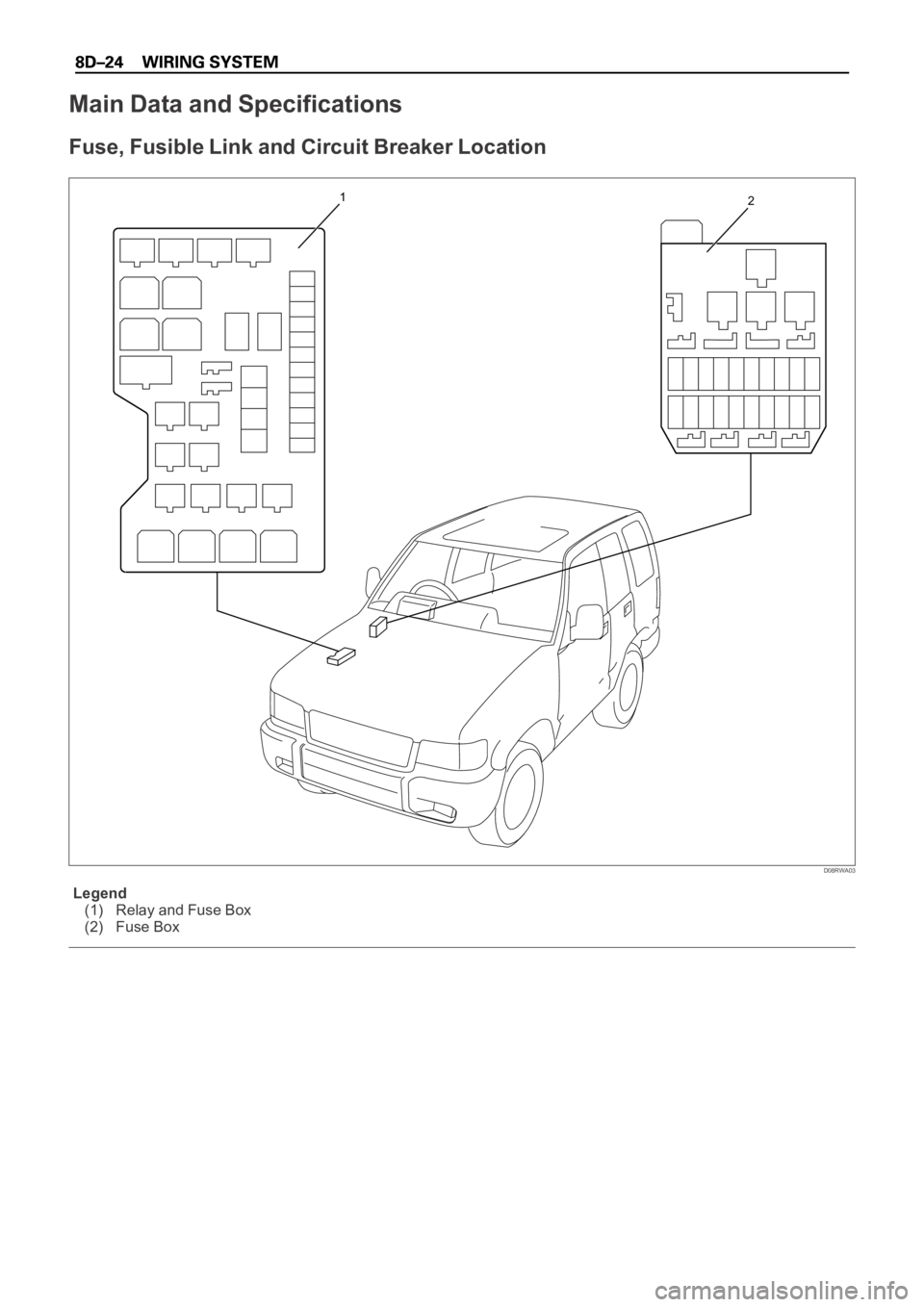
Legend
(1) Relay and Fuse Box
(2) Fuse Box
Main Data and Specifications
Fuse, Fusible Link and Circuit Breaker Location
Page 2647 of 6000
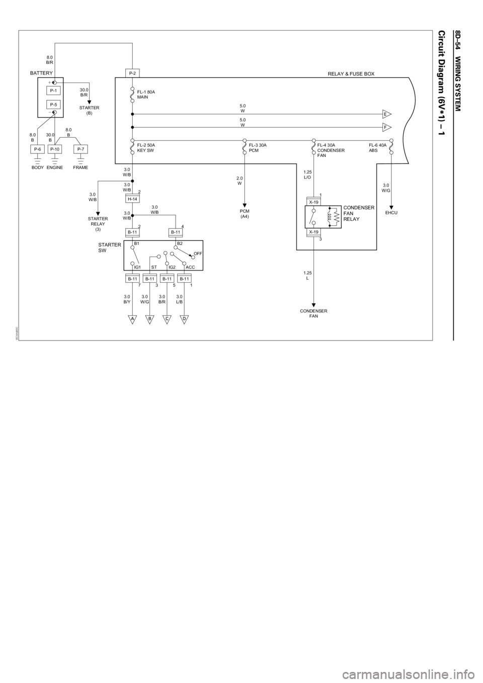
3
P-2
H-142
2
B-11
P-10P-7
PCM
(A4)
CONDENSER
FANEHCU STARTER
(B)
STARTER
RELAY
(3)
P-6
BODY ENGINE FRAME
BATTERY
STARTER
SWRELAY & FUSE BOX
CONDENSER
FAN
RELAY
FL-2 50A
KEY SWFL-3 30A
PCMFL-4 30A
CONDENSER
FANFL-6 40A
ABS FL-1 80A
MAIN 8.0
B/R
8.0
B30.0
B8.0
B30.0
B/R
3.0
W/B
3.0
W/B
3.0
W/B
3.0
B/Y3.0
W/G3.0
B/R3.0
L/B2.0
W1.25
L/O
1.25
L3.0
W/G
3.0
W/B5.0
W
5.0
W
3.0
W/B
B-11IG1 ST IG2 ACC B1
7B-11
3B-11
5B-11
1
B2
OFF 4
B-11
P-5
P-1�+
�−
X-191
X-19
D08RWC56.