engine OPEL FRONTERA 1998 Workshop Manual
[x] Cancel search | Manufacturer: OPEL, Model Year: 1998, Model line: FRONTERA, Model: OPEL FRONTERA 1998Pages: 6000, PDF Size: 97 MB
Page 1090 of 6000
6D2–5
IGNITION SYSTEM
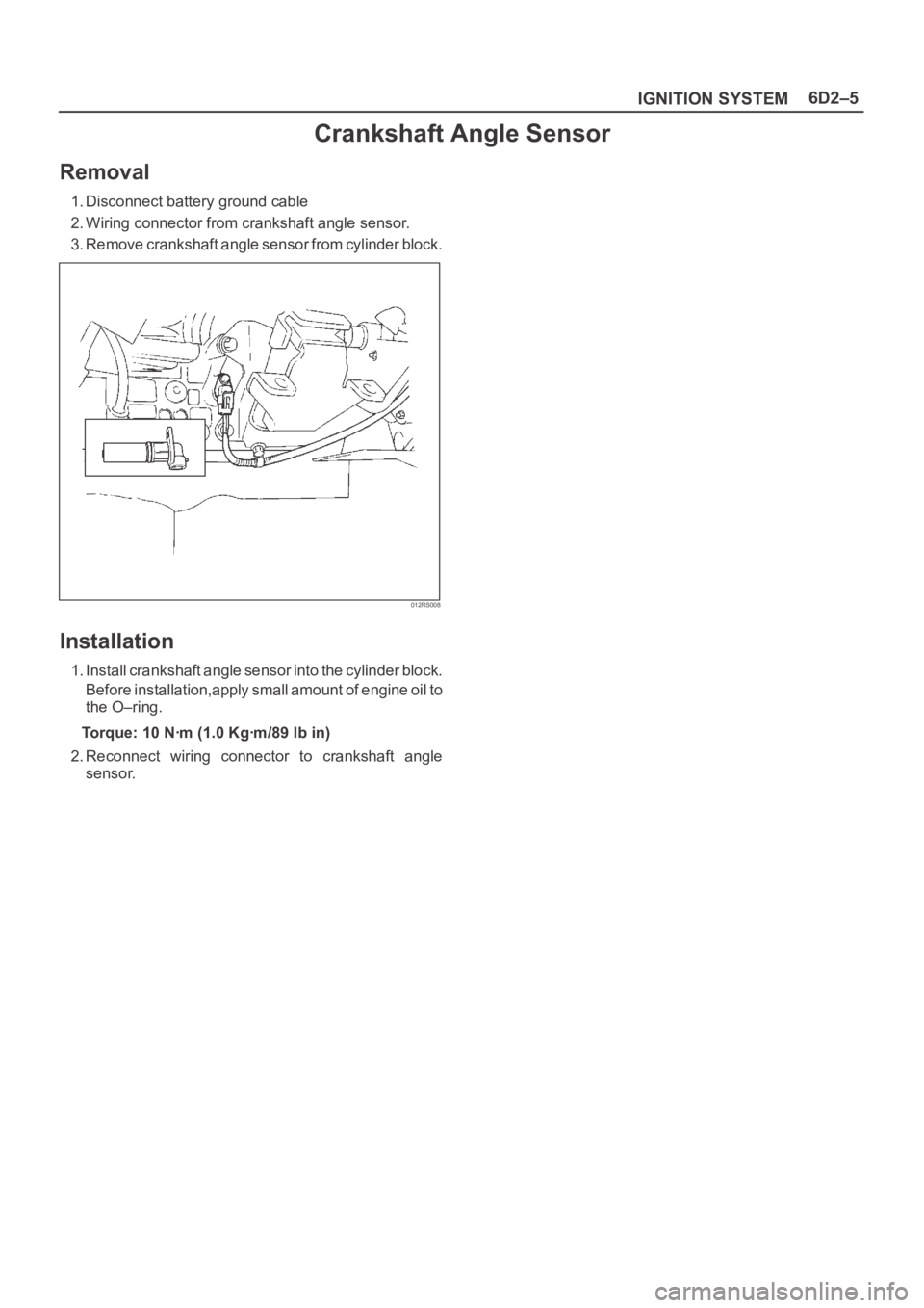
Crankshaft Angle Sensor
Removal
1. Disconnect battery ground cable
2. Wiring connector from crankshaft angle sensor.
3. Remove crankshaft angle sensor from cylinder block.
012RS008
Installation
1. Install crankshaft angle sensor into the cylinder block.
Before installation,apply small amount of engine oil to
the O–ring.
Torque: 10 Nꞏm (1.0 Kgꞏm/89 lb in)
2. Reconnect wiring connector to crankshaft angle
sensor.
Page 1092 of 6000
6D3–1 STARTING AND CHARGING SYSTEM
ENGINE
STARTING AND CHARGING SYSTEM
CONTENTS
Service Precaution 6D3–1. . . . . . . . . . . . . . . . . . . . . .
Starting System 6D3–2. . . . . . . . . . . . . . . . . . . . . . . . .
General Description 6D3–2. . . . . . . . . . . . . . . . . . . . .
Diagnosis 6D3–4. . . . . . . . . . . . . . . . . . . . . . . . . . . . . .
Starter 6D3–5. . . . . . . . . . . . . . . . . . . . . . . . . . . . . . . . .
Removal 6D3–5. . . . . . . . . . . . . . . . . . . . . . . . . . . . .
Installation 6D3–5. . . . . . . . . . . . . . . . . . . . . . . . . . . .
Disassembled View 6D3–6. . . . . . . . . . . . . . . . . . . .
Disassembly 6D3–7. . . . . . . . . . . . . . . . . . . . . . . . . .
Inspection and Repair 6D3–9. . . . . . . . . . . . . . . . . .
Reassembly 6D3–13. . . . . . . . . . . . . . . . . . . . . . . . . .
Main Data and Specifications 6D3–15. . . . . . . . . . .
Charging System 6D3–18. . . . . . . . . . . . . . . . . . . . . . . . General Description 6D3–18. . . . . . . . . . . . . . . . . . . . .
General On–Vehicle Inspection 6D3–18. . . . . . . . . . .
Generator 6D3–19. . . . . . . . . . . . . . . . . . . . . . . . . . . . . .
Removal 6D3–19. . . . . . . . . . . . . . . . . . . . . . . . . . . . .
Inspection 6D3–19. . . . . . . . . . . . . . . . . . . . . . . . . . . .
Installation 6D3–19. . . . . . . . . . . . . . . . . . . . . . . . . . . .
Disassembled View 6D3–20. . . . . . . . . . . . . . . . . . . .
Disassembly 6D3–21. . . . . . . . . . . . . . . . . . . . . . . . . .
Inspection and Repair 6D3–23. . . . . . . . . . . . . . . . . .
Reassembly 6D3–24. . . . . . . . . . . . . . . . . . . . . . . . . .
Bench Test 6D3–25. . . . . . . . . . . . . . . . . . . . . . . . . . .
Main Data and Specifications 6D3–26. . . . . . . . . . .
Service Precaution
WARNING: IF SO EQUIPPED WITH A
SUPPLEMENTAL RESTRAINT SYSTEM (SRS),
REFER TO THE SRS COMPONENT AND WIRING
LOCATION VIEW IN ORDER TO DETERMINE
WHETHER YOU ARE PERFORMING SERVICE ON OR
NEAR THE SRS COMPONENTS OR THE SRS
WIRING. WHEN YOU ARE PERFORMING SERVICE
ON OR NEAR THE SRS COMPONENTS OR THE SRS
WIRING, REFER TO THE SRS SERVICE
INFORMATION. FAILURE TO FOLLOW WARNINGS
COULD RESULT IN POSSIBLE AIR BAG
DEPLOYMENT, PERSONAL INJURY, OR
OTHERWISE UNNEEDED SRS SYSTEM REPAIRS.
CAUTION: Always use the correct fastener in the
proper location. When you replace a fastener, use
ONLY the exact part number for that application.
ISUZU will call out those fasteners that require a
replacement after removal. ISUZU will also call out
the fasteners that require thread lockers or thread
sealant. UNLESS OTHERWISE SPECIFIED, do not
use supplemental coatings (Paints, greases, or other
corrosion inhibitors) on threaded fasteners or
fastener joint interfaces. Generally, such coatings
adversely affect the fastener torque and the joint
clamping force, and may damage the fastener. When
you install fasteners, use the correct tightening
sequence and specifications. Following these
instructions can help you avoid damage to parts and
systems.
Page 1093 of 6000
6D3–2STARTING AND CHARGING SYSTEM
Starting System
General Description
Cranking Circuit
The cranking system consists of a battery, starter, starter
switch, starter relay, etc. These main components are
connected.
Starter
The cranking system employs a magnetic type reduction
starter in which the motor shaft is also used as a pinion
shaft. When the starter switch is turned on, the contacts of
magnetic switch are closed, and the armature rotates. At
the same time, the plunger is attracted, and the pinion is
pushed forward by the shift lever to mesh with the ring
gear.
Then, the ring gear runs to start the engine. When the
engine starts and the starter switch is turned off, the
plunger returns, the pinion is disengaged from the ring
gear, and the armature stops rotation. When the engine
speed is higher than the pinion, the pinion idles, so that
the armature is not driven.
Page 1096 of 6000
6D3–5 STARTING AND CHARGING SYSTEM
Starter
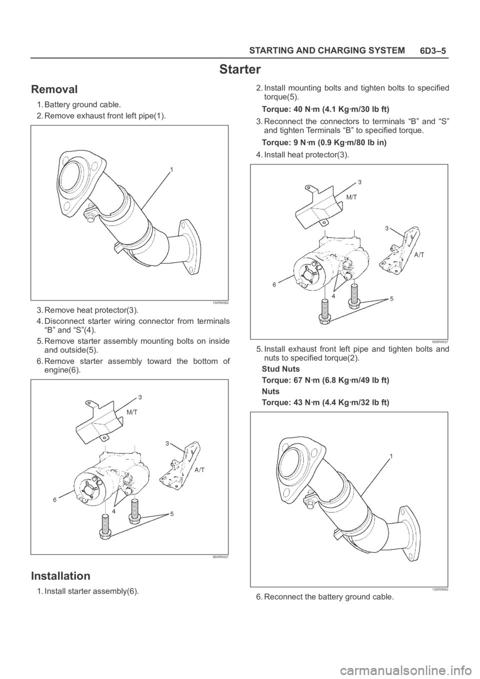
Removal
1. Battery ground cable.
2. Remove exhaust front left pipe(1).
150RW062
3. Remove heat protector(3).
4. Disconnect starter wiring connector from terminals
“B” and “S”(4).
5. Remove starter assembly mounting bolts on inside
and outside(5).
6. Remove starter assembly toward the bottom of
engine(6).
065RW027
Installation
1. Install starter assembly(6).2. Install mounting bolts and tighten bolts to specified
torque(5).
Torque: 40 Nꞏm (4.1 Kgꞏm/30 lb ft)
3. Reconnect the connectors to terminals “B” and “S”
and tighten Terminals “B” to specified torque.
Torque: 9 Nꞏm (0.9 Kgꞏm/80 lb in)
4. Install heat protector(3).
065RW027
5. Install exhaust front left pipe and tighten bolts and
nuts to specified torque(2).
Stud Nuts
Torque: 67 Nꞏm (6.8 Kgꞏm/49 lb ft)
Nuts
Torque: 43 Nꞏm (4.4 Kgꞏm/32 lb ft)
150RW062
6. Reconnect the battery ground cable.
Page 1109 of 6000
6D3–18STARTING AND CHARGING SYSTEM
Charging System
General Description
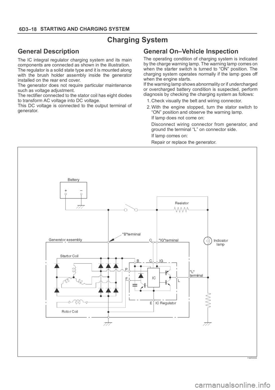
The IC integral regulator charging system and its main
components are connected as shown in the illustration.
The regulator is a solid state type and it is mounted along
with the brush holder assembly inside the generator
installed on the rear end cover.
The generator does not require particular maintenance
such as voltage adjustment.
The rectifier connected to the stator coil has eight diodes
to transform AC voltage into DC voltage.
This DC voltage is connected to the output terminal of
generator.
General On–Vehicle Inspection
The operating condition of charging system is indicated
by the charge warning lamp. The warning lamp comes on
when the starter switch is turned to “ON” position. The
charging system operates normally if the lamp goes off
when the engine starts.
If the warning lamp shows abnormality or if undercharged
or overcharged battery condition is suspected, perform
diagnosis by checking the charging system as follows:
1. Check visually the belt and wiring connector.
2. With the engine stopped, turn the stator switch to
“ON” position and observe the warning lamp.
If lamp does not come on:
Disconnect wiring connector from generator, and
ground the terminal “L” on connector side.
If lamp comes on:
Repair or replace the generator.
F06RW009
Page 1110 of 6000
6D3–19 STARTING AND CHARGING SYSTEM
Generator
Removal
1. Disconnect battery ground cable.
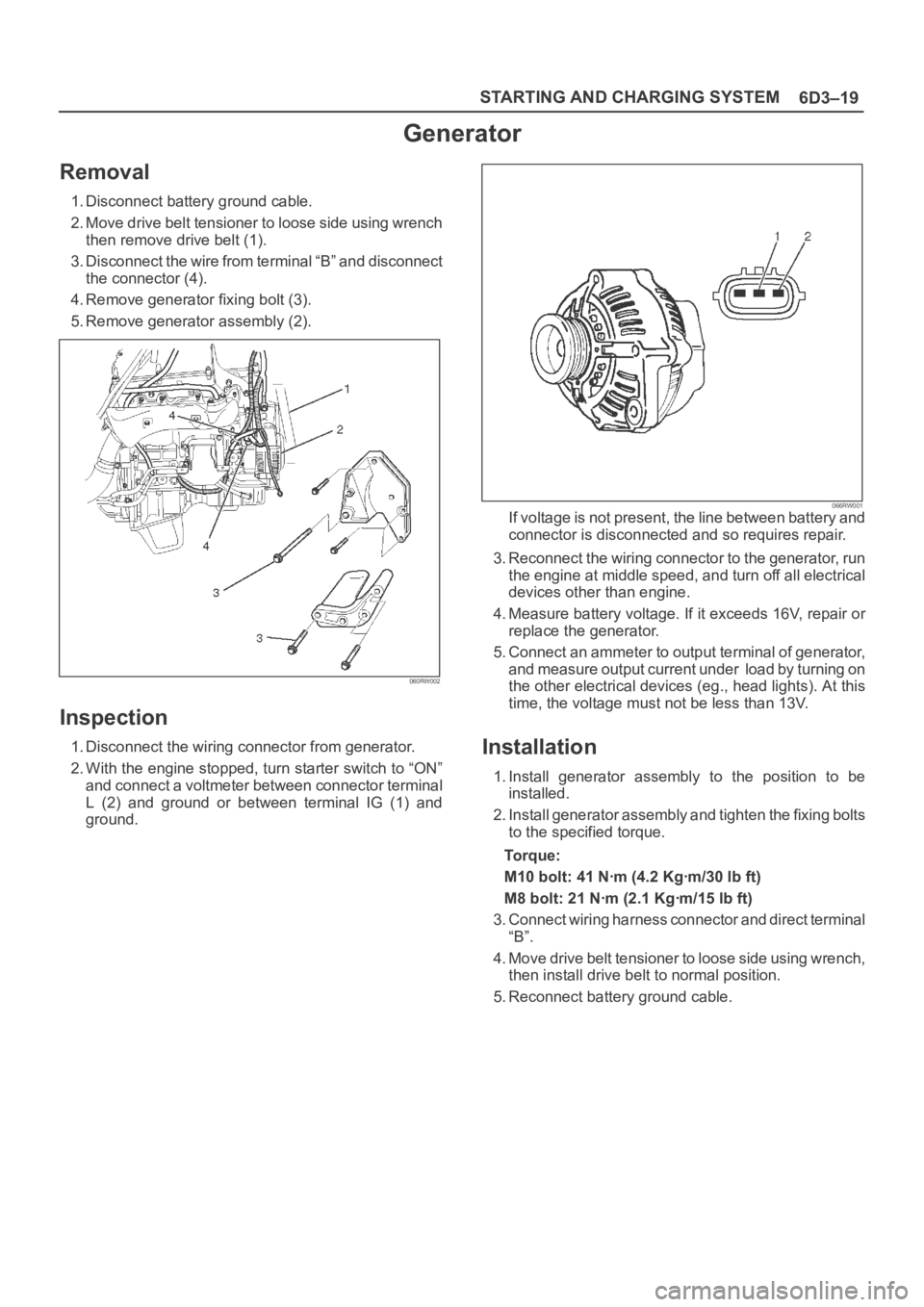
2. Move drive belt tensioner to loose side using wrench
then remove drive belt (1).
3. Disconnect the wire from terminal “B” and disconnect
the connector (4).
4. Remove generator fixing bolt (3).
5. Remove generator assembly (2).
060RW002
Inspection
1. Disconnect the wiring connector from generator.
2. With the engine stopped, turn starter switch to “ON”
and connect a voltmeter between connector terminal
L (2) and ground or between terminal IG (1) and
ground.
066RW001If voltage is not present, the line between battery and
connector is disconnected and so requires repair.
3. Reconnect the wiring connector to the generator, run
the engine at middle speed, and turn off all electrical
devices other than engine.
4. Measure battery voltage. If it exceeds 16V, repair or
replace the generator.
5. Connect an ammeter to output terminal of generator,
and measure output current under load by turning on
the other electrical devices (eg., head lights). At this
time, the voltage must not be less than 13V.
Installation
1. Install generator assembly to the position to be
installed.
2. Install generator assembly and tighten the fixing bolts
to the specified torque.
To r q u e :
M10 bolt: 41 Nꞏm (4.2 Kgꞏm/30 lb ft)
M8 bolt: 21 Nꞏm (2.1 Kgꞏm/15 lb ft)
3. Connect wiring harness connector and direct terminal
“B”.
4. Move drive belt tensioner to loose side using wrench,
then install drive belt to normal position.
5. Reconnect battery ground cable.
Page 1118 of 6000
6E–1 ENGINE DRIVEABILITY AND EMISSIONS
ENGINE
ENGINE DRIVEABILITY AND EMISSIONS
CONTENTS
Specifications 6E–5. . . . . . . . . . . . . . . . . . . . . . . . .
Tightening Specifications 6E–5. . . . . . . . . . . . . . .
Vehicle Type Specifications 6E–5. . . . . . . . . . . . .
Diagrams and Schematics 6E–6. . . . . . . . . . . . . . . .
PCM Wiring Diagram (1 of 11) 6E–6. . . . . . . . . . .
PCM Wiring Diagram (2 of 11) For EC,
THAILAND, SOUTH EAST ASIA, LATIN
AMERICA, GULF, SAUDI, CHINA. 6E–7. . . . . .
PCM Wiring Diagram (3 of 11) For SOUTH
AFRICA and EXP. 6E–8. . . . . . . . . . . . . . . . . . . . .
PCM Wiring Diagram (4 of 11) 6E–9. . . . . . . . . . .
PCM Wiring Diagram (5 of 11) 6E–10. . . . . . . . . . .
PCM Wiring Diagram (6 of 11) For
AUSTRALIA, THAILAND, SOUTH EAST
ASIA, LATIN AMERICA, GULF, SAUDI,
LATIN AMERICA. 6E–11. . . . . . . . . . . . . . . . . . . . .
PCM Wiring Diagram (7 of 11) For EC. 6E–12. . .
PCM Wiring Diagram (8 of 11) For EXPORT
and SOUTH AFRICA. 6E–13. . . . . . . . . . . . . . . . .
PCM Wiring Diagram (9 of 11) Except EXP
and SOUTH AFRICA 6E–14. . . . . . . . . . . . . . . . . .
PCM Wiring Diagram (10 of 11) For
EXPORT and SOUTH AFRICA 6E–15. . . . . . . . .
PCM Wiring Diagram (11 of 11) 6E–16. . . . . . . . . .
PCM Pinouts 6E–17. . . . . . . . . . . . . . . . . . . . . . . . . . .
PCM Pinout Table, 32-Way Red
Connector – Row “A” 6E–17. . . . . . . . . . . . . . . . . .
PCM Pinout Table, 32-Way Red
Connector – Row “B” 6E–19. . . . . . . . . . . . . . . . . .
PCM Pinout Table, 32-Way White
Connector – Row “C” (For EC) 6E–20. . . . . . . . . .
PCM Pinout Table, 32-Way White
Connector – Row “C” (For except EC) 6E–21. . .
PCM Pinout Table, 32-Way White
Connector – Row “D”
(For except EXPORT and SOUTH
AFRICA) 6E–22. . . . . . . . . . . . . . . . . . . . . . . . . . . . .
PCM Pinout Table, 32-Way White
Connector – Row “D”
(For EXPORT and SOUTH AFRICA) 6E–23. . . . .
PCM Pinout Table, 32-Way Blue
Connector – Row “E”
(For except EXPORT and SOUTH
AFRICA) 6E–24. . . . . . . . . . . . . . . . . . . . . . . . . . . . .
PCM Pinout Table, 32-Way Blue
Connector – Row “E”
(For EXPORT and SOUTH AFRICA) 6E–26. . . . .
PCM Pinout Table, 32-Way Blue
Connector – Row “F” 6E–27. . . . . . . . . . . . . . . . . .
Component Locators 6E–28. . . . . . . . . . . . . . . . . . . .
Engine Component Locator (This illustration
is based on RHD model.) 6E–28. . . . . . . . . . . . . . Engine Component Locator Table 6E–29. . . . . . . .
Engine Component Locator Table 6E–31. . . . . . . .
Undercarriage Component Locator 6E–32. . . . . .
Undercarriage Component Locator Table
(Automatic Transmission) 6E–32. . . . . . . . . . . . . .
Undercarriage Component Locator Table
(Manual Transmission) 6E–33. . . . . . . . . . . . . . . .
Fuse and Relay Panel (Underhood
Electrical Center) 6E–33. . . . . . . . . . . . . . . . . . . . .
Sensors and Miscellaneous Component
Locators 6E–34. . . . . . . . . . . . . . . . . . . . . . . . . . . . .
Diagnosis 6E–37. . . . . . . . . . . . . . . . . . . . . . . . . . . . . .
Strategy-Based Diagnostics 6E–37. . . . . . . . . . . . .
Strategy-Based Diagnostics 6E–37. . . . . . . . . . . . .
DTC Stored 6E–37
. . . . . . . . . . . . . . . . . . . . . . . . . . .
No DTC 6E–37. . . . . . . . . . . . . . . . . . . . . . . . . . . . . .
No Matching Symptom 6E–37. . . . . . . . . . . . . . . . .
Intermittents 6E–37. . . . . . . . . . . . . . . . . . . . . . . . . .
No Trouble Found 6E–37. . . . . . . . . . . . . . . . . . . . .
Verifying Vehicle Repair 6E–37. . . . . . . . . . . . . . . .
General Service Information 6E–38. . . . . . . . . . . . . .
OBD Serviceablity Issues 6E–38. . . . . . . . . . . . . . .
Maintenance Schedule 6E–38. . . . . . . . . . . . . . . . .
Visual / Physical Engine Compartment
Inspection 6E–38. . . . . . . . . . . . . . . . . . . . . . . . . . . .
Basic Knowledge of Tools Required 6E–38. . . . . .
Serial Data Communications 6E–38. . . . . . . . . . . . . .
Class II Serial Data Communications 6E–38. . . . .
On-Board Diagnostic (OBD) 6E–39. . . . . . . . . . . . . .
On-Board Diagnostic Tests 6E–39. . . . . . . . . . . . .
Comprehensive Component Monitor
Diagnostic Operation 6E–39. . . . . . . . . . . . . . . . . .
Common OBD Terms 6E–40. . . . . . . . . . . . . . . . . .
The Diagnostic Executive 6E–40. . . . . . . . . . . . . . .
DTC Types 6E–41. . . . . . . . . . . . . . . . . . . . . . . . . . .
Verifying Vehicle Repair 6E–42. . . . . . . . . . . . . . . .
Reading Diagnostic Trouble Codes Using
A Tech 2 6E–42. . . . . . . . . . . . . . . . . . . . . . . . . . . . .
Tech 2 Tech 2 6E–43. . . . . . . . . . . . . . . . . . . . . . . . .
Tech 2 Features 6E–43. . . . . . . . . . . . . . . . . . . . . . .
Getting Started 6E–44. . . . . . . . . . . . . . . . . . . . . . . .
Operating Procedure (For Example) 6E–44. . . . .
DTC Modes 6E–45. . . . . . . . . . . . . . . . . . . . . . . . . . .
DTC Information Mode 6E–46. . . . . . . . . . . . . . . . .
Injector Balance Test 6E–46. . . . . . . . . . . . . . . . . . .
EGR Control Test 6E–47. . . . . . . . . . . . . . . . . . . . . .
Idle Air Control System Test 6E–48. . . . . . . . . . . . .
Page 1119 of 6000
6E–2
ENGINE DRIVEABILITY AND EMISSIONS
Primary System-Based Diagnostic 6E–50. . . . . . . . .
Primary System-Based Diagnostic 6E–50. . . . . . .
Fuel Control Heated Oxygen Sensor 6E–50. . . . .
HO2S Heater 6E–50. . . . . . . . . . . . . . . . . . . . . . . . .
Fuel Trim System Monitor Diagnostic
Operation 6E–50. . . . . . . . . . . . . . . . . . . . . . . . . . . . . .
Fuel Trim System Monitor Diagnostic
Operation 6E–50. . . . . . . . . . . . . . . . . . . . . . . . . . . .
Fuel Trim Cell Diagnostic Weights 6E–50. . . . . . .
On-Board Diagnostic (OBD) System Check 6E–51.
A/C Clutch Control Circuit Diagnosis 6E–54. . . . . . .
Electronic Ignition System Diagnosis 6E–60. . . . . . .
Fuel Metering System Check 6E–60. . . . . . . . . . . . .
Idle Air Control (IAC) Valve 6E–60. . . . . . . . . . . . . . .
Fuel System Pressure Test 6E–60. . . . . . . . . . . . . . .
Fuel Injector Coil Test Procedure and Fuel
Injector Balance Test Procedure 6E–60. . . . . . . . . .
Knock Sensor Diagnosis 6E–65. . . . . . . . . . . . . . . . .
Powertrain Control Module (PCM) Diagnosis 6E–65
Multiple PCM Information Sensor DTCS Set 6E–65
Exhaust Gas Recirculation (EGR) Diagnosis
(For except EXPORT and
SOUTH AFRICA) 6E–68. . . . . . . . . . . . . . . . . . . . . . .
Engine Tech 2 Data Definitions and Ranges 6E–68
Typical Scan Data Values 6E–70. . . . . . . . . . . . . . . .
No Malfunction Indicator Lamp (MIL) 6E–74. . . . . . .
Malfunction Indicator Lamp (MIL) “ON”
Steady 6E–77. . . . . . . . . . . . . . . . . . . . . . . . . . . . . . . .
Engine Cranks But Will Not Run 6E–79. . . . . . . . . . .
Fuel System Electrical Test 6E–85. . . . . . . . . . . . . . .
Fuel System Diagnosis 6E–88. . . . . . . . . . . . . . . . . . .
Idle Air Control (IAC) System Check 6E–93. . . . . . .
Knock Sensor (KS) System Check
(Engine Knock, Poor Performance, or Poor
Economy) 6E–95. . . . . . . . . . . . . . . . . . . . . . . . . . . . .
Exhaust Gas Recirculation (EGR) System
Check 6E–97. . . . . . . . . . . . . . . . . . . . . . . . . . . . . . . . .
Manifold Absolute Pressure (MAP) Output
Check 6E–99. . . . . . . . . . . . . . . . . . . . . . . . . . . . . . . . .
PCM Diagnostic Trouble Codes 6E–101. . . . . . . . . . .
Diagnostic Trouble Code (DTC) P0101
MAF System Performance 6E–104. . . . . . . . . . . . . . .
Diagnostic Trouble Code (DTC) P0102
MAF Sensor Circuit Low Frequency 6E–107. . . . . .
Diagnostic Trouble Code (DTC) P0103
MAF Sensor Circuit High Frequency 6E–110. . . . . .
Diagnostic Trouble Code (DTC) P0107
MAP Sensor Circuit Low Voltage 6E–112. . . . . . . . . .
Diagnostic Trouble Code (DTC) P0108
MAP Sensor Circuit High Voltage 6E–115. . . . . . . . .
Diagnostic Trouble Code (DTC) P0112
IAT Sensor Circuit Low Voltage 6E–118. . . . . . . . . . .
Diagnostic Trouble Code (DTC) P0113
IAT Sensor Circuit High Voltage 6E–121. . . . . . . . . . Diagnostic Trouble Code (DTC) P0117
ECT Sensor Circuit Low Voltage 6E–124. . . . . . . . . .
Diagnostic Trouble Code (DTC) P0118
ECT Sensor Circuit High Voltage 6E–127. . . . . . . . .
Diagnostic Trouble Code (DTC) P0121
TP System Performance 6E–130. . . . . . . . . . . . . . . . .
Diagnostic Trouble Code (DTC) P0122
TP Sensor Circuit Low Voltage 6E–133. . . . . . . . . . .
Diagnostic Trouble Code (DTC) P0123
TP Sensor Circuit High Voltage 6E–136. . . . . . . . . .
Diagnostic Trouble Code (DTC) P0131
HO2S Circuit Low Voltage Bank 1
Sensor 1 6E–139. . . . . . . . . . . . . . . . . . . . . . . . . . . . . . .
Diagnostic Trouble Code (DTC) P0132
HO2S Circuit High Voltage Bank 1
Sensor 1 6E–142. . . . . . . . . . . . . . . . . . . . . . . . . . . . . . .
Diagnostic Trouble Code (DTC) P0134
HO2S Circuit Insufficient Activity Bank 1
Sensor 1 6E–145. . . . . . . . . . . . . . . . . . . . . . . . . . . . . .
Diagnostic Trouble Code (DTC) P0151
HO2S Circuit Low Voltage Bank 2
Sensor 1 6E–148. . . . . . . . . . . . . . . . . . . . . . . . . . . . . . .
Diagnostic Trouble Code (DTC) P0152
HO2S Circuit HIGH Voltage Bank 2
Sensor 1 6E–151. . . . . . . . . . . . . . . . . . . . . . . . . . . . . . .
Diagnostic Trouble Code (DTC) P0171
Fuel Trim System Lean Bank 1 6E–154. . . . . . . . . . .
Diagnostic Trouble Code (DTC) P0172
Fuel Trim System Rich Bank 1 6E–158. . . . . . . . . . .
Diagnostic Trouble Code (DTC) P0174
Fuel Trim System Lean Bank 2 6E–162. . . . . . . . . . .
Diagnostic Trouble Code (DTC) P0175
Fuel Trim System Rich Bank 2 6E–166. . . . . . . . . . .
Diagnostic Trouble Code (DTC) P0201
Injector 1 Control Circuit 6E–170. . . . . . . . . . . . . . . . .
Diagnostic Trouble Code (DTC) P0202
Injector 2 Control Circuit 6E–173. . . . . . . . . . . . . . . . .
Diagnostic Trouble Code (DTC) P0203
Injector 3 Control Circuit 6E–176. . . . . . . . . . . . . . . . .
Diagnostic Trouble Code (DTC) P0204
Injector 4 Control Circuit 6E–179. . . . . . . . . . . . . . . . .
Diagnostic Trouble Code (DTC) P0205
Injector 5 Control Circuit 6E–182. . . . . . . . . . . . . . . . .
Diagnostic Trouble Code (DTC) P0206
Injector 6 Control Circuit 6E–185. . . . . . . . . . . . . . . . .
Diagnostic Trouble Code (DTC) P0325
KS Module Circuit 6E–188. . . . . . . . . . . . . . . . . . . . . .
Diagnostic Trouble Code (DTC) P0327
KS Sensor Circuit 6E–190. . . . . . . . . . . . . . . . . . . . . . .
Diagnostic Trouble Code (DTC) P0336
58X Reference Signal Circuit 6E–193. . . . . . . . . . . . .
Diagnostic Trouble Code (DTC) P0337
CKP Sensor Circuit Low Frequency 6E–195. . . . . . .
Diagnostic Trouble Code (DTC) P0341
CMP Sensor Circuit Performance 6E–198. . . . . . . . .
Diagnostic Trouble Code (DTC) P0342
CMP Sensor Circuit Low 6E–202. . . . . . . . . . . . . . . . .
Page 1120 of 6000

6E–3 ENGINE DRIVEABILITY AND EMISSIONS
Diagnostic Trouble Code (DTC) P0351
Ignition 1 Control Circuit 6E–206. . . . . . . . . . . . . . . . .
Diagnostic Trouble Code (DTC) P0352
Ignition 2 Control Circuit 6E–209. . . . . . . . . . . . . . . . .
Diagnostic Trouble Code (DTC) P0353
Ignition 3 Control Circuit 6E–212. . . . . . . . . . . . . . . . .
Diagnostic Trouble Code (DTC) P0354
Ignition 4 Control Circuit 6E–215. . . . . . . . . . . . . . . . .
Diagnostic Trouble Code (DTC) P0355
Ignition 5 Control Circuit 6E–218. . . . . . . . . . . . . . . . .
Diagnostic Trouble Code (DTC) P0356
Ignition 6 Control Circuit 6E–221. . . . . . . . . . . . . . . . .
Diagnostic Trouble Code (DTC) P0402
EGR Pintle Crank Error 6E–224. . . . . . . . . . . . . . . . . .
Diagnostic Trouble Code (DTC) P0404
EGR Open Stuck 6E–226. . . . . . . . . . . . . . . . . . . . . . .
Diagnostic Trouble Code (DTC) P0405
EGR Low Voltage 6E–228. . . . . . . . . . . . . . . . . . . . . . .
Diagnostic Trouble Code (DTC) P0406
EGR High Voltage 6E–231. . . . . . . . . . . . . . . . . . . . . .
Diagnostic Trouble Code (DTC) P0502
VSS Circuit Low Input 6E–234. . . . . . . . . . . . . . . . . . .
Diagnostic Trouble Code (DTC) P0562
System Voltage Low 6E–237. . . . . . . . . . . . . . . . . . . .
Diagnostic Trouble Code (DTC) P0563
System Voltage High 6E–239. . . . . . . . . . . . . . . . . . . .
Diagnostic Trouble Code (DTC) P0601
PCM Memory 6E–240. . . . . . . . . . . . . . . . . . . . . . . . . .
Diagnostic Trouble Code (DTC) P1154
HO2S Circuit Transition Time Ratio Bank 2
Sensor 1 6E–241. . . . . . . . . . . . . . . . . . . . . . . . . . . . . .
Diagnostic Trouble Code (DTC) P1171
Fuel System Lean During Acceleration 6E–245. . . .
Diagnostic Trouble Code (DTC) P1380
ABS Rough Road ABS System Fault 6E–248. . . . . .
Diagnostic Trouble Code (DTC) P1404
EGR Closed Stuck 6E–249. . . . . . . . . . . . . . . . . . . . . .
Diagnostic Trouble Code (DTC) P1508
IAC System Low RPM 6E–251. . . . . . . . . . . . . . . . . . .
Diagnostic Trouble Code (DTC) P1509
IAC System High RPM 6E–254. . . . . . . . . . . . . . . . . .
Diagnostic Trouble Code (DTC) P1618
Serial Peripheral Interface (SPI) PCM
Interprocessor Communication Error 6E–257. . . . . .
Diagnostic Trouble Code (DTC) P1625
PCM Unexpected Reset 6E–258. . . . . . . . . . . . . . . . .
Diagnostic Trouble Code (DTC) P1640
Driver-1-Input High Voltage 6E–259. . . . . . . . . . . . . .
Symptom Diagnosis 6E–262. . . . . . . . . . . . . . . . . . . . .
Default Matrix Table 6E–288. . . . . . . . . . . . . . . . . . . . .
Camshaft Position (CMP) Sensor 6E–291. . . . . . . . . .
Crankshaft Position (CKP) Sensor 6E–292. . . . . . . . .
Engine Coolant Temperature (ECT) Sensor 6E–292.
Heated Oxygen Sensor (HO2S) 6E–293. . . . . . . . . . .
Intake Air Temperature (IAT) Sensor 6E–295. . . . . . .
Knock Sensor (KS) 6E–296. . . . . . . . . . . . . . . . . . . . . . Mass Air Flow (MAF) Sensor 6E–297. . . . . . . . . . . . .
Manifold Absolute Pressure (MAP) Sensor 6E–297.
Malfunction Indicator Lamp (MIL) 6E–298. . . . . . . . . .
Powertrain Control Module (PCM) 6E–298. . . . . . . . .
EEPROM 6E–300. . . . . . . . . . . . . . . . . . . . . . . . . . . . . .
Power Steering Pressure (PSP) Switch 6E–300
. . . .
Throttle Position (TP) Sensor 6E–301. . . . . . . . . . . . .
Vehicle Speed Sensor (VSS) 6E–302. . . . . . . . . . . . .
Air Cleaner/Air Filter 6E–303. . . . . . . . . . . . . . . . . . . . .
Idle Air Control (IAC) Valve 6E–304. . . . . . . . . . . . . . .
Common Chamber 6E–305. . . . . . . . . . . . . . . . . . . . . .
Accelerator Cable Assembly 6E–305. . . . . . . . . . . . . .
Accelerator Pedal Replacement 6E–308. . . . . . . . . . .
Fuel Filter Cap 6E–310. . . . . . . . . . . . . . . . . . . . . . . . . .
Fuel Filter 6E–310. . . . . . . . . . . . . . . . . . . . . . . . . . . . . .
Fuel Gauge Unit 6E–313. . . . . . . . . . . . . . . . . . . . . . . .
Fuel Injectors 6E–314. . . . . . . . . . . . . . . . . . . . . . . . . . .
Fuel Pressure Regulator 6E–315. . . . . . . . . . . . . . . . .
Fuel Metering System 6E–317. . . . . . . . . . . . . . . . . . . .
Fuel Pump Assembly 6E–318. . . . . . . . . . . . . . . . . . . .
Fuel Pump Relay 6E–319. . . . . . . . . . . . . . . . . . . . . . . .
Fuel Rail Assembly 6E–319. . . . . . . . . . . . . . . . . . . . . .
Fuel Tank 6E–321. . . . . . . . . . . . . . . . . . . . . . . . . . . . . .
Throttle Body (TB) 6E–323. . . . . . . . . . . . . . . . . . . . . . .
Electronic Ignition System 6E–324. . . . . . . . . . . . . . . .
Catalytic Converter 6E–325. . . . . . . . . . . . . . . . . . . . . .
Air Conditioning Relay 6E–325. . . . . . . . . . . . . . . . . . .
EVAP Canister Hoses 6E–326. . . . . . . . . . . . . . . . . . . .
EVAP Canister 6E–326. . . . . . . . . . . . . . . . . . . . . . . . . .
EVAP Canister Purge Solenoid 6E–327. . . . . . . . . . . .
Fuel Tank Vent Valve 6E–328. . . . . . . . . . . . . . . . . . . .
Linear Exhaust Gas Recirculation
(EGR) Valve 6E–328. . . . . . . . . . . . . . . . . . . . . . . . . . .
Positive Crankcase Ventilation (PCV) Valve 6E–329.
Wiring and Connectors 6E–330. . . . . . . . . . . . . . . . . . .
PCM Connectors and Terminals 6E–330. . . . . . . . . . .
Wire Harness Repair: Twisted Shielded
Cable 6E–330. . . . . . . . . . . . . . . . . . . . . . . . . . . . . . . . .
Twisted Leads 6E–331. . . . . . . . . . . . . . . . . . . . . . . . . .
Weather-Pack Connector 6E–332. . . . . . . . . . . . . . . . .
Com-Pack III 6E–333. . . . . . . . . . . . . . . . . . . . . . . . . . .
Metri-Pack 6E–333. . . . . . . . . . . . . . . . . . . . . . . . . . . . .
General Description 6E–335. . . . . . . . . . . . . . . . . . . . .
General Description (PCM and Sensors) 6E–335. . .
58X Reference PCM Input 6E–335. . . . . . . . . . . . . .
A/C Request Signal 6E–335. . . . . . . . . . . . . . . . . . . .
Crankshaft Position (CKP) Sensor 6E–335. . . . . . .
Camshaft Position (CMP) Sensor and
Signal 6E–335. . . . . . . . . . . . . . . . . . . . . . . . . . . . . . .
Engine Coolant Temperature (ECT) Sensor 6E–335
Electrically Erasable Programmable Read
Only Memory (EEPROM) 6E–336. . . . . . . . . . . . . .
Fuel Control Heated Oxygen Sensors 6E–336. . . .
Intake Air Temperature (IAT) Sensor 6E–336. . . . .
Page 1121 of 6000
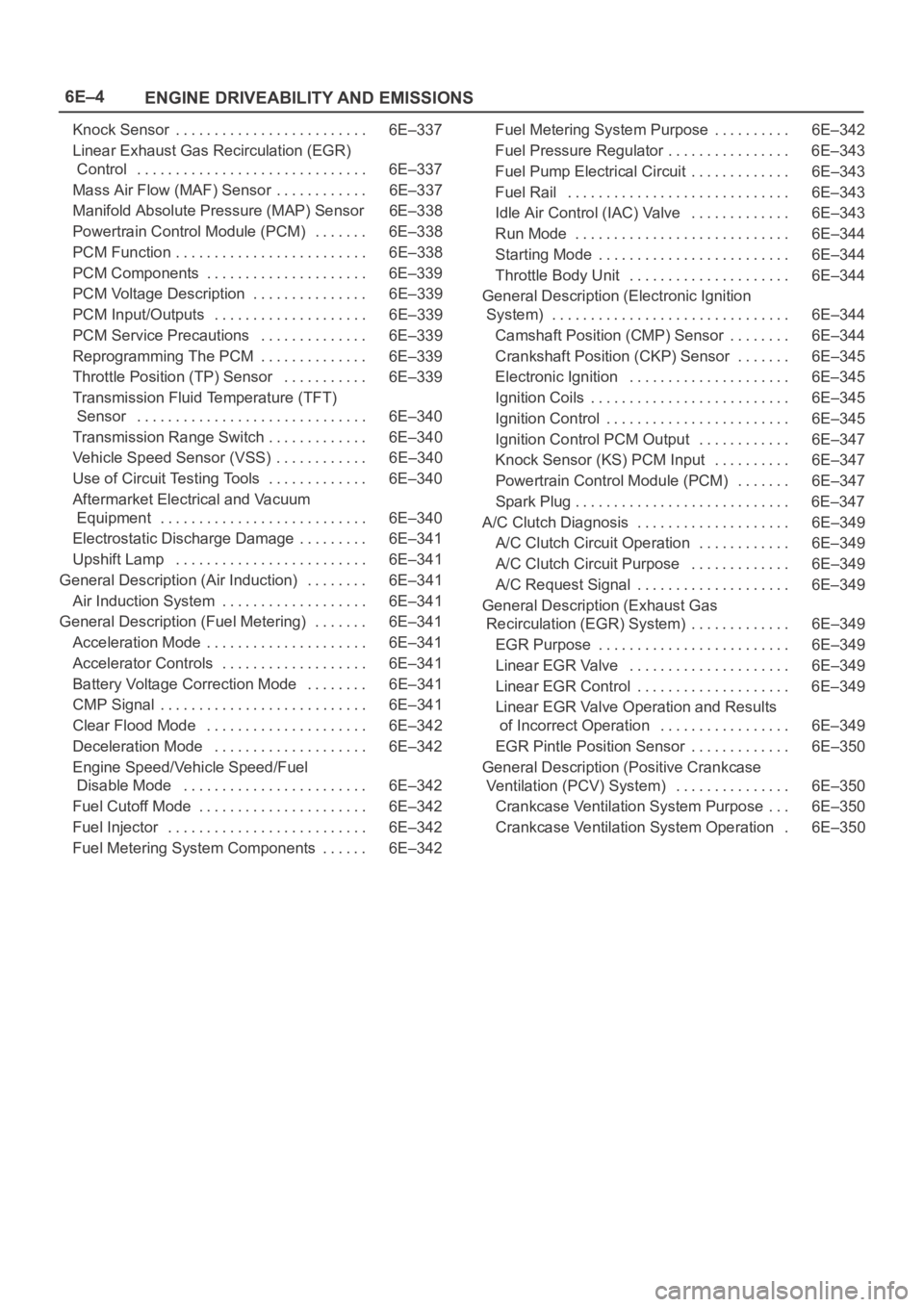
6E–4
ENGINE DRIVEABILITY AND EMISSIONS
Knock Sensor 6E–337. . . . . . . . . . . . . . . . . . . . . . . . .
Linear Exhaust Gas Recirculation (EGR)
Control 6E–337. . . . . . . . . . . . . . . . . . . . . . . . . . . . . .
Mass Air Flow (MAF) Sensor 6E–337. . . . . . . . . . . .
Manifold Absolute Pressure (MAP) Sensor 6E–338
Powertrain Control Module (PCM) 6E–338. . . . . . .
PCM Function 6E–338. . . . . . . . . . . . . . . . . . . . . . . . .
PCM Components 6E–339. . . . . . . . . . . . . . . . . . . . .
PCM Voltage Description 6E–339. . . . . . . . . . . . . . .
PCM Input/Outputs 6E–339. . . . . . . . . . . . . . . . . . . .
PCM Service Precautions 6E–339. . . . . . . . . . . . . .
Reprogramming The PCM 6E–339. . . . . . . . . . . . . .
Throttle Position (TP) Sensor 6E–339. . . . . . . . . . .
Transmission Fluid Temperature (TFT)
Sensor 6E–340. . . . . . . . . . . . . . . . . . . . . . . . . . . . . .
Transmission Range Switch 6E–340. . . . . . . . . . . . .
Vehicle Speed Sensor (VSS) 6E–340. . . . . . . . . . . .
Use of Circuit Testing Tools 6E–340. . . . . . . . . . . . .
Aftermarket Electrical and Vacuum
Equipment 6E–340. . . . . . . . . . . . . . . . . . . . . . . . . . .
Electrostatic Discharge Damage 6E–341. . . . . . . . .
Upshift Lamp 6E–341. . . . . . . . . . . . . . . . . . . . . . . . .
General Description (Air Induction) 6E–341. . . . . . . .
Air Induction System 6E–341. . . . . . . . . . . . . . . . . . .
General Description (Fuel Metering) 6E–341. . . . . . .
Acceleration Mode 6E–341. . . . . . . . . . . . . . . . . . . . .
Accelerator Controls 6E–341. . . . . . . . . . . . . . . . . . .
Battery Voltage Correction Mode 6E–341. . . . . . . .
CMP Signal 6E–341. . . . . . . . . . . . . . . . . . . . . . . . . . .
Clear Flood Mode 6E–342. . . . . . . . . . . . . . . . . . . . .
Deceleration Mode 6E–342. . . . . . . . . . . . . . . . . . . .
Engine Speed/Vehicle Speed/Fuel
Disable Mode 6E–342. . . . . . . . . . . . . . . . . . . . . . . .
Fuel Cutoff Mode 6E–342. . . . . . . . . . . . . . . . . . . . . .
Fuel Injector 6E–342. . . . . . . . . . . . . . . . . . . . . . . . . .
Fuel Metering System Components 6E–342. . . . . . Fuel Metering System Purpose 6E–342. . . . . . . . . .
Fuel Pressure Regulator 6E–343. . . . . . . . . . . . . . . .
Fuel Pump Electrical Circuit 6E–343. . . . . . . . . . . . .
Fuel Rail 6E–343. . . . . . . . . . . . . . . . . . . . . . . . . . . . .
Idle Air Control (IAC) Valve 6E–343. . . . . . . . . . . . .
Run Mode 6E–344. . . . . . . . . . . . . . . . . . . . . . . . . . . .
Starting Mode 6E–344. . . . . . . . . . . . . . . . . . . . . . . . .
Throttle Body Unit 6E–344. . . . . . . . . . . . . . . . . . . . .
General Description (Electronic Ignition
System) 6E–344. . . . . . . . . . . . . . . . . . . . . . . . . . . . . . .
Camshaft Position (CMP) Sensor 6E–344. . . . . . . .
Crankshaft Position (CKP) Sensor 6E–345. . . . . . .
Electronic Ignition 6E–345. . . . . . . . . . . . . . . . . . . . .
Ignition Coils 6E–345. . . . . . . . . . . . . . . . . . . . . . . . . .
Ignition Control 6E–345. . . . . . . . . . . . . . . . . . . . . . . .
Ignition Control PCM Output 6E–347. . . . . . . . . . . .
Knock Sensor (KS) PCM Input 6E–347
. . . . . . . . . .
Powertrain Control Module (PCM) 6E–347. . . . . . .
Spark Plug 6E–347. . . . . . . . . . . . . . . . . . . . . . . . . . . .
A/C Clutch Diagnosis 6E–349. . . . . . . . . . . . . . . . . . . .
A/C Clutch Circuit Operation 6E–349. . . . . . . . . . . .
A/C Clutch Circuit Purpose 6E–349. . . . . . . . . . . . .
A/C Request Signal 6E–349. . . . . . . . . . . . . . . . . . . .
General Description (Exhaust Gas
Recirculation (EGR) System) 6E–349. . . . . . . . . . . . .
EGR Purpose 6E–349. . . . . . . . . . . . . . . . . . . . . . . . .
Linear EGR Valve 6E–349. . . . . . . . . . . . . . . . . . . . .
Linear EGR Control 6E–349. . . . . . . . . . . . . . . . . . . .
Linear EGR Valve Operation and Results
of Incorrect Operation 6E–349. . . . . . . . . . . . . . . . .
EGR Pintle Position Sensor 6E–350. . . . . . . . . . . . .
General Description (Positive Crankcase
Ventilation (PCV) System) 6E–350. . . . . . . . . . . . . . .
Crankcase Ventilation System Purpose 6E–350. . .
Crankcase Ventilation System Operation 6E–350.