ESP inoperative OPEL FRONTERA 1998 Workshop Manual
[x] Cancel search | Manufacturer: OPEL, Model Year: 1998, Model line: FRONTERA, Model: OPEL FRONTERA 1998Pages: 6000, PDF Size: 97 MB
Page 1460 of 6000

6E–343 ENGINE DRIVEABILITY AND EMISSIONS
constant measuring and adjusting of the air/fuel ratio, the
fuel injection system is called a “closed loop” system.
The PCM monitors signals from several sensors in order
to determine the fuel needs of the engine. Fuel is
delivered under one of several conditions called “modes.”
All modes are controlled by the PCM.
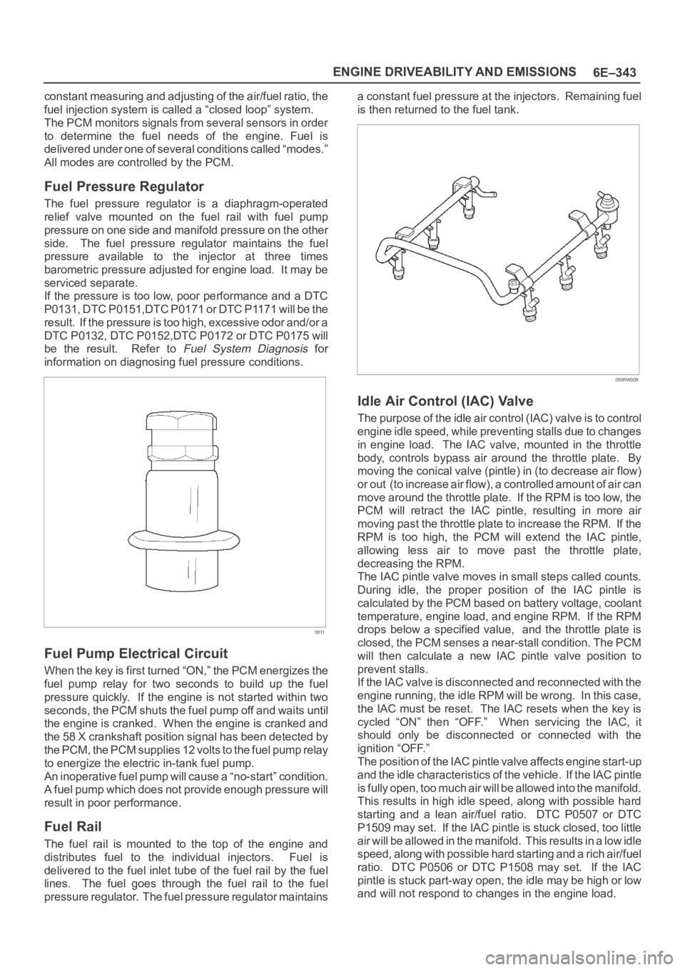
Fuel Pressure Regulator
The fuel pressure regulator is a diaphragm-operated
relief valve mounted on the fuel rail with fuel pump
pressure on one side and manifold pressure on the other
side. The fuel pressure regulator maintains the fuel
pressure available to the injector at three times
barometric pressure adjusted for engine load. It may be
serviced separate.
If the pressure is too low, poor performance and a DTC
P0131, DTC P0151,DTC P0171 or DTC P1171 will be the
result. If the pressure is too high, excessive odor and/or a
DTC P0132, DTC P0152,DTC P0172 or DTC P0175 will
be the result. Refer to
Fuel System Diagnosis for
information on diagnosing fuel pressure conditions.
0011
Fuel Pump Electrical Circuit
When the key is first turned “ON,” the PCM energizes the
fuel pump relay for two seconds to build up the fuel
pressure quickly. If the engine is not started within two
seconds, the PCM shuts the fuel pump off and waits until
the engine is cranked. When the engine is cranked and
the 58 X crankshaft position signal has been detected by
the PCM, the PCM supplies 12 volts to the fuel pump relay
to energize the electric in-tank fuel pump.
An inoperative fuel pump will cause a “no-start” condition.
A fuel pump which does not provide enough pressure will
result in poor performance.
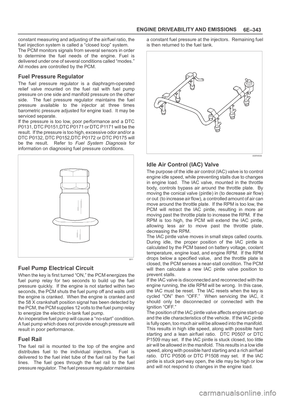
Fuel Rail
The fuel rail is mounted to the top of the engine and
distributes fuel to the individual injectors. Fuel is
delivered to the fuel inlet tube of the fuel rail by the fuel
lines. The fuel goes through the fuel rail to the fuel
pressure regulator. The fuel pressure regulator maintainsa constant fuel pressure at the injectors. Remaining fuel
is then returned to the fuel tank.
055RW009
Idle Air Control (IAC) Valve
The purpose of the idle air control (IAC) valve is to control
engine idle speed, while preventing stalls due to changes
in engine load. The IAC valve, mounted in the throttle
body, controls bypass air around the throttle plate. By
moving the conical valve (pintle) in (to decrease air flow)
or out (to increase air flow), a controlled amount of air can
move around the throttle plate. If the RPM is too low, the
PCM will retract the IAC pintle, resulting in more air
moving past the throttle plate to increase the RPM. If the
RPM is too high, the PCM will extend the IAC pintle,
allowing less air to move past the throttle plate,
decreasing the RPM.
The IAC pintle valve moves in small steps called counts.
During idle, the proper position of the IAC pintle is
calculated by the PCM based on battery voltage, coolant
temperature, engine load, and engine RPM. If the RPM
drops below a specified value, and the throttle plate is
closed, the PCM senses a near-stall condition. The PCM
will then calculate a new IAC pintle valve position to
prevent stalls.
If the IAC valve is disconnected and reconnected with the
engine running, the idle RPM will be wrong. In this case,
the IAC must be reset. The IAC resets when the key is
cycled “ON” then “OFF.” When servicing the IAC, it
should only be disconnected or connected with the
ignition “OFF.”
The position of the IAC pintle valve affects engine start-up
and the idle characteristics of the vehicle. If the IAC pintle
is fully open, too much air will be allowed into the manifold.
This results in high idle speed, along with possible hard
starting and a lean air/fuel ratio. DTC P0507 or DTC
P1509 may set. If the IAC pintle is stuck closed, too little
air will be allowed in the manifold. This results in a low idle
speed, along with possible hard starting and a rich air/fuel
ratio. DTC P0506 or DTC P1508 may set. If the IAC
pintle is stuck part-way open, the idle may be high or low
and will not respond to changes in the engine load.
Page 2266 of 6000

TRANSMISSION CONTROL SYSTEM (4L30–E)7A1–21
NOTE: To use the DTC again to identify a problem, you
will need to reproduce the fault or the problem. This may
require a new test drive or just turning the ignition on (this
depends on the nature of the fault).
1. IF you have a Tech2:
1. Connect the Tech2 if it is still not connected
GOTHROUGH Tech2 OBD II CONNECTION.
2. Push “F4” and answer “Yes” to the question “Do
you really want to clear the codes?”
a. When a malfunction remains as it is the Tech2
displays “4L30E CODES NOT CLEARED”. This
means that the problem is still there or that the
recovery was not done. Please GOTO DTC
CHECK.
b. When a malfunction has been repaired and the
recovery is done. The Tech2 displays “4L30E
CODES CLEARED”.
2. IF you have no Tech2:
To clear the DTC, remove Fuse “Stop, A/T CONT”
(C–14, 15A) for at least 10 seconds.
DTC Check
1. Diagnostic Trouble Codes (DTC) have been identified
by Tech2.
2. You have written the list of the DTCs. The order of the
malfunctions has no meanings for this PCM. Usually
only one or two malfunctions should be set for a given
problem.
3. Check directly the DTCs you identified. The DTCs are
sorted by number. Refer to Diagnostic Trouble Code
(DTC) Identification in this section.
PCM Precaution
The PCM can be damaged by:
1. Electrostatic discharge
2. The short circuit of some terminals to voltage or to
ground.
Electrostatic Discharge Damage Description:
1. Electronic components used to control systems are
often designed to carry very low voltage, and are very
susceptible to damage caused by electrostatic
discharge. It is possible for less than 100 volts of
static electricity to cause damage to some electronic
components. By comparison, it takes as much as
4,000 volts for a person to even feel the zap of a static
discharge.2. There are several ways for a person to become
statically charged. The most common methods of
charging are by friction and induction. An example of
charging by friction is a person sliding across a car
seat, in which a charge of as much as 25,000 volts
can build up. Charging by induction occurs when a
person with well insulated shoes stands near a highly
charged object and momentarily touches ground.
Charges for the same polarity are drained off, leaving
the person highly charged with the opposite polarity.
Static charges of either type can cause damage,
therefore, it is important to use care when handling
and testing electronic components.
NOTICE: To prevent possible electrostatic
discharge damage:
1. Do not touch the PCM connector pins or soldered
components on the PCM circuit board.
2. Be sure to follow the guidelines listed below if
servicing any of these electronic components:
3. Do not open the replacement part package until it is
time to install the part.
4. Avoid touching electrical terminals of the part.
5. Before removing the part from its package, ground
the package to a known good ground on the vehicle.
6. Always touch a known good ground before handling
the part. This step should be repeated before
installing the part if the part has been handled while
sliding across the seat, while sitting down from a
standing position or while walking some distance.
Information On PCM
1. The Powertrain Control Module (PCM) is located in
the center console and is the control center of the
electronic transmission control system.
2. The PCM must be maintained at a temperature below
185
F (85C) at all times. This is most essential if the
vehicle is put through a paint baking process. The
PCM will become inoperative if its temperature
exceeds 85
C (185F). Therefore, it is
recommended that the PCM be removed or that
temporary insulation be placed around the PCM
during the time the vehicle is in a paint oven or other
high temperature process.
3. The PCM is designed to process the various inputs
and then respond by sending the appropriate
electrical signals to control transmission upshift,
downshift, shift feel and torque converter clutch
engagement.
4. The PCM constantly interprets information from the
various sensors, and controls the systems that affect
transmission and vehicle performance. By analyzing
operational problems, the PCM is able to perform a
diagnostic function by displaying DTC(s) and aid the
technician in making repairs.
Intermittent Conditions
If the Tech2 displays a diagnostic trouble code as
intermittent, or if after a test drive a DTC does not
reappear though the detection conditions for this DTC are
present, the problem is most likely a faulty electrical
Page 5000 of 6000

6E–343 ENGINE DRIVEABILITY AND EMISSIONS
constant measuring and adjusting of the air/fuel ratio, the
fuel injection system is called a “closed loop” system.
The PCM monitors signals from several sensors in order
to determine the fuel needs of the engine. Fuel is
delivered under one of several conditions called “modes.”
All modes are controlled by the PCM.
Fuel Pressure Regulator
The fuel pressure regulator is a diaphragm-operated
relief valve mounted on the fuel rail with fuel pump
pressure on one side and manifold pressure on the other
side. The fuel pressure regulator maintains the fuel
pressure available to the injector at three times
barometric pressure adjusted for engine load. It may be
serviced separate.
If the pressure is too low, poor performance and a DTC
P0131, DTC P0151,DTC P0171 or DTC P1171 will be the
result. If the pressure is too high, excessive odor and/or a
DTC P0132, DTC P0152,DTC P0172 or DTC P0175 will
be the result. Refer to
Fuel System Diagnosis for
information on diagnosing fuel pressure conditions.
0011
Fuel Pump Electrical Circuit
When the key is first turned “ON,” the PCM energizes the
fuel pump relay for two seconds to build up the fuel
pressure quickly. If the engine is not started within two
seconds, the PCM shuts the fuel pump off and waits until
the engine is cranked. When the engine is cranked and
the 58 X crankshaft position signal has been detected by
the PCM, the PCM supplies 12 volts to the fuel pump relay
to energize the electric in-tank fuel pump.
An inoperative fuel pump will cause a “no-start” condition.
A fuel pump which does not provide enough pressure will
result in poor performance.
Fuel Rail
The fuel rail is mounted to the top of the engine and
distributes fuel to the individual injectors. Fuel is
delivered to the fuel inlet tube of the fuel rail by the fuel
lines. The fuel goes through the fuel rail to the fuel
pressure regulator. The fuel pressure regulator maintainsa constant fuel pressure at the injectors. Remaining fuel
is then returned to the fuel tank.
055RW009
Idle Air Control (IAC) Valve
The purpose of the idle air control (IAC) valve is to control
engine idle speed, while preventing stalls due to changes
in engine load. The IAC valve, mounted in the throttle
body, controls bypass air around the throttle plate. By
moving the conical valve (pintle) in (to decrease air flow)
or out (to increase air flow), a controlled amount of air can
move around the throttle plate. If the RPM is too low, the
PCM will retract the IAC pintle, resulting in more air
moving past the throttle plate to increase the RPM. If the
RPM is too high, the PCM will extend the IAC pintle,
allowing less air to move past the throttle plate,
decreasing the RPM.
The IAC pintle valve moves in small steps called counts.
During idle, the proper position of the IAC pintle is
calculated by the PCM based on battery voltage, coolant
temperature, engine load, and engine RPM. If the RPM
drops below a specified value, and the throttle plate is
closed, the PCM senses a near-stall condition. The PCM
will then calculate a new IAC pintle valve position to
prevent stalls.
If the IAC valve is disconnected and reconnected with the
engine running, the idle RPM will be wrong. In this case,
the IAC must be reset. The IAC resets when the key is
cycled “ON” then “OFF.” When servicing the IAC, it
should only be disconnected or connected with the
ignition “OFF.”
The position of the IAC pintle valve affects engine start-up
and the idle characteristics of the vehicle. If the IAC pintle
is fully open, too much air will be allowed into the manifold.
This results in high idle speed, along with possible hard
starting and a lean air/fuel ratio. DTC P0507 or DTC
P1509 may set. If the IAC pintle is stuck closed, too little
air will be allowed in the manifold. This results in a low idle
speed, along with possible hard starting and a rich air/fuel
ratio. DTC P0506 or DTC P1508 may set. If the IAC
pintle is stuck part-way open, the idle may be high or low
and will not respond to changes in the engine load.