warning OPEL FRONTERA 1998 Workshop Manual
[x] Cancel search | Manufacturer: OPEL, Model Year: 1998, Model line: FRONTERA, Model: OPEL FRONTERA 1998Pages: 6000, PDF Size: 97 MB
Page 5788 of 6000

AUTOMATIC TRANSMISSION (AW30-40LE) 7A–7
CONTROL AND FUNCTIONS
Item Description
Shift and lock-up control • In D range, speed change point and Lock-up point can be changed by
setting pattern selection switch to "POWER", "NORMAL" or "WINTER"
mode.
• Gear shift position in the conditions made up of transmission shift positions
(D.2.L) combined with pattern selection switch (POWER, NORMAL, and
WINTER) can be controlled in accordance with vehicle speed and the
opening of throttle valve.
Overdrive cut control • If O/D OFF switch is set on in D range (O/D OFF lamp ON), gear shift to O/
D is not effected.
• Overdrive is released at O/D OFF switch on and high transmission oil
temperature (More than 130
C).
However, to prevent engine over revolution
•4
3 shifting at vehicle speed is less than 118 km/h.
•3
4 shifting at vehicle speed is more than 131 km/h.
Lock-up cut control • In D range, 3rd or O/D lock-up is conducted in "POWER" or "NORMAL"
mode.
• In 2, L range, lock-up is off in the whole area.
• Lock-up timing is controlled to reduce gear shift shock using kind of gear
shift (shift up, etc.) lock-up status at the time of gear shift judgement, gear
step and throttle opening after gear shift.
• Lock-up is released at brake on or high transmission oil temperature (More
than 130
C).
• Lock-up is prohibited when idling is defected by throttle position sensor.
Driving mode select control • The TCM selects a suitable driving mode from the nine kinds for the variety
driving condition.
i) Economy mode ii) Power mode iii) Winter mode iv) HOT1 mode v) HOT2
mode vi) L4 mode vii) Slope mode (Up slope 1, Up slope 2 and Down
slope mode)
• The priority of driving mode:
Economy < Power < Slope < L4 < Winter < HOT1 < HOT2
Squat control • When the TCM detects D signal on, the TCM controls 1–3–1 shift by
setting a timer, in order to improve the shift feel at N
D.
Line pressure control • The TCM output current which corresponds to throttle oil pressure to
pressure control solenoid based on throttle opening.
Indicate oil temperature warning
function• If the transmission oil temperature sensor senses that transmission oil
temperature is greater than 146
C, the TCM turn on A/T OIL TEMP
warning lamp. (The warning lamp is turned off, if oil temperature is less
than 126
C.)
L4 mode control • The TCM judges whether the transfer is engaged in high or low based on
the ratio rpm data from output speed sensor in the transmission and the
rpm data from speed meter sensor to select the shift map.
Up and down hill control • The TCM judges up and down hill, and change shift pattern based on
throttle opening and acceleration.
Correct oil temperature control • If the temperature exceeds a predetermined value, the TCM selects the
high oil temperature shift point for downshifting, thus preventing the oil
temperature from rising. (More than 130
C, D range)
Page 5790 of 6000

AUTOMATIC TRANSMISSION (AW30-40LE) 7A–9
MAJOR INPUT/OUTPUT COMPONENTS
Component Function
Input
Vehicle speed sensor (Speedometer) Detects the vehicle speed (Back-up sensor of output
revolution sensor).
Output revolution sensor (Transmission) Detects the vehicle speed.
Input revolution sensor (Transmission) Detects the input revolution (O/D direct clutch drum
revolution).
Engine revolution sensor Detects the engine revolution.
Throttle position sensor Detects the throttle opening rate.
Neutral start switch Detects the select lever position.
Pattern select switch Detects whether the driver has selected "NORMAL",
"POWER", or "WINTER" mode.
Overdrive off switch Detects whether the driver has selected O/D.
Brake lamp switch Detects whether the driver has pressed the brake pedal or
not.
Oil temperature sensor Detects the oil temperature.
Diagnostic star t switch Star ts self-diagnosis and displays a code for faulty part if
any.
Input/Output
Data link connector When connected with Tech2 or tester, can communicate
the data for function check, etc.
Output
Shift solenoid S1, S2 Selects shift point and gear position suited to the vehicle
running condition on the basis of TCM output.
Lock-up control solenoid SL Control the lock-up clutch suited to the vehicle running
condition on the basis of TCM output.
Pressure control solenoid STH Adjusts throttle pressure by energizing current of linear
pressure control solenoid to prevent the shift shock and to
obtain shift smoothly.
"CHECK TRANS" lamp When trouble has occurred to throttle position sensor,
vehicle speed sensor, or solenoid, "CHECK TRANS" lamp
is blinked to warn the driver. If also displays the trouble
code.
A/T OIL TEMP warning lamp Lights when ATF oil temperature rises. (Turned on at
greater than 146
C . Turned off at less than 126C.
Power mode lamp Informs the driver whether the vehicle is in power mode or
not.
Winter mode lamp Informs the driver whether the vehicle is in winter mode or
not.
Computer
Transmission Control Module (TCM) Based on the signal from each switch and sensors, judges
necessary shift point and lock-up operation, and send
signal to each solenoid.
Page 5795 of 6000

7A–14 AUTOMATIC TRANSMISSION (AW30-40LE)
821RY00012
F07LV002
740RY00013
740RY00014
SELF-DIAGNOSIS
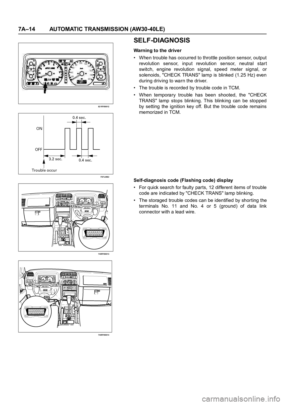
Warning to the driver
• When trouble has occurred to throttle position sensor, output
revolution sensor, input revolution sensor, neutral star t
switch, engine revolution signal, speed meter signal, or
solenoids, "CHECK TRANS" lamp is blinked (1.25 Hz) even
during driving to warn the driver.
• The trouble is recorded by trouble code in TCM.
• When temporary trouble has been shooted, the "CHECK
TRANS" lamp stops blinking. This blinking can be stopped
by setting the ignition key off. But the trouble code remains
memorized in TCM.
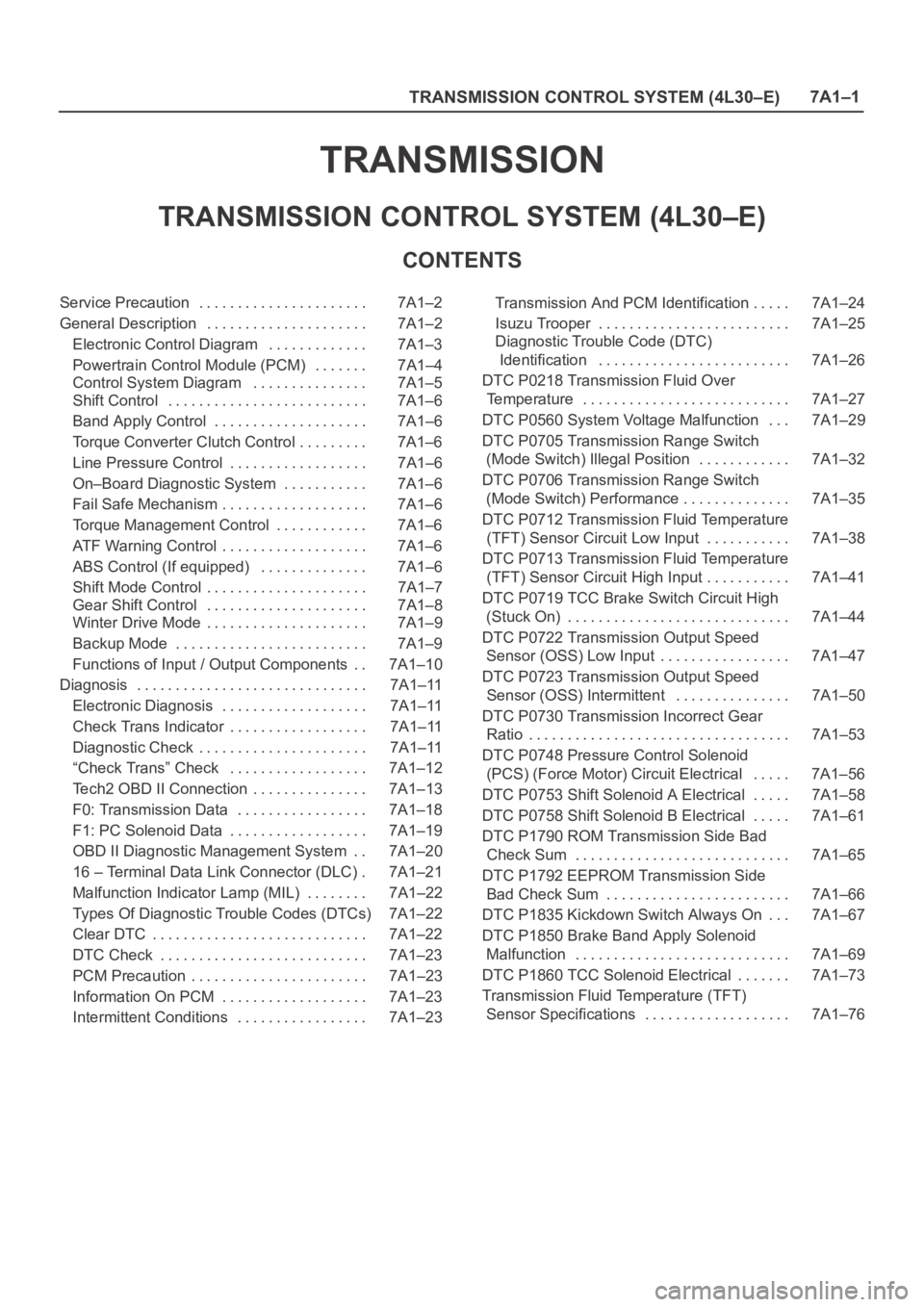
Self-diagnosis code (Flashing code) display
• For quick search for faulty parts, 12 different items of trouble
code are indicated by "CHECK TRANS" lamp blinking.
• The storaged trouble codes can be identified by shor ting the
terminals No. 11 and No. 4 or 5 (ground) of data link
connector with a lead wire.
Page 5801 of 6000

7A–20 AUTOMATIC TRANSMISSION (AW30-40LE)
Once the test vehicle has been identified an “Application
(Power train) Menu" screen appears. Please select the
appropriate application.
The following table shows, which functions are used for
the available equipment versions.
Diagnostic Trouble Codes
The purpose of the “Diagnostic Trouble Codes" mode is
to display stored TCM trouble codes.
When “Diagnostic Trouble Codes" is selected an
“Application Menu" screen appears.
Clear DTC Information
The purpose of the “Clear DTC Information" mode is to
command the clearing of stored TCM trouble codes.
When “Clear DTC Information" is selected, a “Clear
DTC Information", warning screen appears. This screen
informs you that by cleaning DTC's, “all stored DTC
information in controller will be erased".
Do you want to clear DTC's (Yes/No).
Press either the Yes or No key when answering.
After clearing codes, confirm system operation by test
driving the vehicle.
Allow the vehicle to shift through all four forward gears in
a manner which attempts to repeat the failure condition.
NOTE: When the trouble has not been repaired and thetrouble code cannot be erased, check the vehicle again.
DTC Information
When “DTC Information" is selected, an “Application
Menu" appears with a list of DTC information function
keys addressing DTC specifics and their origins.
Function key selections may vary for particular vehicle
and/or system.
Data Display
The purpose of the “Data Display" mode is to
continuously monitor data parameters.
The current actual values of all impor tant sensors and
signals in the system are display through F1 mode.
When “Data Display" is selected an “Application Menu"
appears.
See “TRANSMISSION DATA" and “TCC DATA” on next
page.
Snapshot
When “Snapshot" is selected an “Application Menu"
appears.
When “Transmission Snapshot" application is selected
from the “Application Menu", a “Snapshot Menu"
appears, displaying several options. “Snapshot" options
may vary from one system to another.
“Snapshot" allows a recording of all vehicle parameters.
There parameters may then be replayed at a future
point in time.
This action allows you to focus on making the condition
occur, rather than trying to view all of the data in
anticipation of the fault. The snapshot will collect
parameter information around a trigger point that you
select.
When a snapshot is taken. It is recorded onto the
PCMCIA memory card. When the Tech2 is powered
down. Snapshots are not lost.
Actuator Tests
The purpose of “Actuator Tests" mode is to check for
correct operation of electronic system actuators.
Lamps
You can operate the lamps by pressing the ON and OFF
buttons.
Preconditions: P or N position
Solenoid
Solenoid S1(1-2/3-4), S2(2-3) and TCC Solenoid
(Torque Converter Clutch)
You can operate the solenoids by pressing the ON and
OFF buttons.
Preconditions: P or N position, no vehicle speed, no
engine speed
Pressure Control Solenoid (PCS)
You can operate the PC Solenoid by pressing the ON
and OFF buttons. ON will command a maximum current
of 1000 mA and OFF a minimum of 200 mA.
Preconditions: P or N position, no vehicle speed, engine
running F0: Diagnostic Trouble Codes
F0: Read DTC Info Ordered By Priority
F1: Clear DTC Information
F2: DTC Information
F0: History
F1: MIL SVS or Message Requested
F2: Last Test Failed
F3: Test Failed Since Code Cleared
F4: Not Ran Since Code Cleared
F5: Failed This Ignition
F1: Data Display
F0: Transmission Data
F1: TCC Data
F2: Snapshot
F3: Actuator Tests
F0: Lamps
F0: Check Light Test
F1: Power Lamp Test
F2: Winter Lamp Test
F3: AT Oil Temperature Lamp Test
F1: Solenoids
F0: Solenoid 2-3 Test
F1: Solenoid 1-2/3-4 Test
F2: TCC Solenoid Test
F3: Pressure Control Solenoid (PCS)
Page 5853 of 6000

7A–72 AUTOMATIC TRANSMISSION (AW30-40LE)
TCM STANDARD VOLTAGE
Check circuitTe r m i n a l
Measuring condition Voltage (V)
+-
Throttle position sensorC79-6 C79-28Throttle fully opened (WOT) 3.47
4.56
Throttle fully closed (idling) 0.25
0.45
C79-19 C79-18 Key switch ON 4.75
5.25
Output revolution sensor C79-4 C79-16 Engine idling in gear 0
3
Input revolution sensor C79-5 C79-17 Engine idling 0
3
Speed meter sensor C79-7C78-15
or -19Vehicle speed 10
20 km/h Less than 1.4
about 5
Brake switch C78-18C78-15
or -19Depress brake 7
16
Release brake Less than 1
O/D OFF switch C79-3C78-15
or -19O/D OFF switch ON (O/D OFF) 7
16
O/D OFF switch OFF (O/D ON) Less than 1
Neutral start switch
C79-2C78-15
or -19Selector “P” range 7
16
(P) Selector all ranges except “P” Less than 1
Neutral start switch
C79-1C78-15
or -19Selector “R” range 7
16
(R) Selector all ranges except “R” Less than 1
Neutral start switch
C79-9C78-15
or -19Selector “N” range 7
16
(N) Selector all ranges except “N” Less than 1
Neutral start switch
C79-8C78-15
or -19Selector “D” range 7
16
(D) Selector all ranges except “D” Less than 1
Neutral start switch
C79-21C78-15
or -19Selector “2” range 7
16
(2) Selector all ranges except “2” Less than 1
Neutral start switch
C79-20C78-15
or -19Selector “L” range 7
16
(L) Selector all ranges except “L” Less than 1
Engine revolution signal C79-15C78-15
or -19Engine idling Less than 1.4
9 16
Diagnosis terminal C79-24C78-15
or -19Self-diagnosis ON
0
1.5
Power pattern switch C79-23C78-15
or -19Power pattern switch OFF (NORMAL) 8
16
Power pattern switch ON (POWER) Less than 1.4
Winter select switch C79-13C78-15
or -19Switch OFF 8
16
Switch ON Less than 1.4
Electrical source (Battery) C78-13C78-15
or -19—
9
16
Electrical source (Ignition) C78-20C78-15
or -19Key switch ON
9
16
Oil temperature warning lamp C79-11C78-15
or -19Oil temperature warning lamp ON Less than 1
Oil temperature warning lamp OFF 8
16
“CHECK TRANS lamp” C79-10C78-15
or -19“CHECK TRANS” lamp ON Less than 1
“CHECK TRANS” lamp OFF 8
16
Power lamp C79-22C78-15
or -19Power lamp ON Less than 1
Powe r l a m p O F F 8
16
Page 5994 of 6000

TRANSMISSION CONTROL SYSTEM (4L30–E)7A1–1
TRANSMISSION
TRANSMISSION CONTROL SYSTEM (4L30–E)
CONTENTS
Service Precaution 7A1–2. . . . . . . . . . . . . . . . . . . . . .
General Description 7A1–2. . . . . . . . . . . . . . . . . . . . .
Electronic Control Diagram 7A1–3. . . . . . . . . . . . .
Powertrain Control Module (PCM) 7A1–4. . . . . . .
Control System Diagram 7A1–5. . . . . . . . . . . . . . .
Shift Control 7A1–6. . . . . . . . . . . . . . . . . . . . . . . . . .
Band Apply Control 7A1–6. . . . . . . . . . . . . . . . . . . .
Torque Converter Clutch Control 7A1–6. . . . . . . . .
Line Pressure Control 7A1–6. . . . . . . . . . . . . . . . . .
On–Board Diagnostic System 7A1–6. . . . . . . . . . .
Fail Safe Mechanism 7A1–6. . . . . . . . . . . . . . . . . . .
Torque Management Control 7A1–6. . . . . . . . . . . .
ATF Warning Control 7A1–6. . . . . . . . . . . . . . . . . . .
ABS Control (If equipped) 7A1–6. . . . . . . . . . . . . .
Shift Mode Control 7A1–7. . . . . . . . . . . . . . . . . . . . .
Gear Shift Control 7A1–8. . . . . . . . . . . . . . . . . . . . .
Winter Drive Mode 7A1–9. . . . . . . . . . . . . . . . . . . . .
Backup Mode 7A1–9. . . . . . . . . . . . . . . . . . . . . . . . .
Functions of Input / Output Components 7A1–10. .
Diagnosis 7A1–11. . . . . . . . . . . . . . . . . . . . . . . . . . . . . .
Electronic Diagnosis 7A1–11. . . . . . . . . . . . . . . . . . .
Check Trans Indicator 7A1–11. . . . . . . . . . . . . . . . . .
Diagnostic Check 7A1–11. . . . . . . . . . . . . . . . . . . . . .
“Check Trans” Check 7A1–12. . . . . . . . . . . . . . . . . .
Tech2 OBD II Connection 7A1–13. . . . . . . . . . . . . . .
F0: Transmission Data 7A1–18. . . . . . . . . . . . . . . . .
F1: PC Solenoid Data 7A1–19. . . . . . . . . . . . . . . . . .
OBD II Diagnostic Management System 7A1–20. .
16 – Terminal Data Link Connector (DLC) 7A1–21.
Malfunction Indicator Lamp (MIL) 7A1–22. . . . . . . .
Types Of Diagnostic Trouble Codes (DTCs) 7A1–22
Clear DTC 7A1–22. . . . . . . . . . . . . . . . . . . . . . . . . . . .
DTC Check 7A1–23. . . . . . . . . . . . . . . . . . . . . . . . . . .
PCM Precaution 7A1–23. . . . . . . . . . . . . . . . . . . . . . .
Information On PCM 7A1–23. . . . . . . . . . . . . . . . . . .
Intermittent Conditions 7A1–23. . . . . . . . . . . . . . . . . Transmission And PCM Identification 7A1–24. . . . .
Isuzu Trooper 7A1–25. . . . . . . . . . . . . . . . . . . . . . . . .
Diagnostic Trouble Code (DTC)
Identification 7A1–26. . . . . . . . . . . . . . . . . . . . . . . . .
DTC P0218 Transmission Fluid Over
Temperature 7A1–27. . . . . . . . . . . . . . . . . . . . . . . . . . .
DTC P0560 System Voltage Malfunction 7A1–29. . .
DTC P0705 Transmission Range Switch
(Mode Switch) Illegal Position 7A1–32. . . . . . . . . . . .
DTC P0706 Transmission Range Switch
(Mode Switch) Performance 7A1–35. . . . . . . . . . . . . .
DTC P0712 Transmission Fluid Temperature
(TFT) Sensor Circuit Low Input 7A1–38. . . . . . . . . . .
DTC P0713 Transmission Fluid Temperature
(TFT) Sensor Circuit High Input 7A1–41. . . . . . . . . . .
DTC P0719 TCC Brake Switch Circuit High
(Stuck On) 7A1–44. . . . . . . . . . . . . . . . . . . . . . . . . . . . .
DTC P0722 Transmission Output Speed
Sensor (OSS) Low Input 7A1–47
. . . . . . . . . . . . . . . . .
DTC P0723 Transmission Output Speed
Sensor (OSS) Intermittent 7A1–50. . . . . . . . . . . . . . .
DTC P0730 Transmission Incorrect Gear
Ratio 7A1–53. . . . . . . . . . . . . . . . . . . . . . . . . . . . . . . . . .
DTC P0748 Pressure Control Solenoid
(PCS) (Force Motor) Circuit Electrical 7A1–56. . . . .
DTC P0753 Shift Solenoid A Electrical 7A1–58. . . . .
DTC P0758 Shift Solenoid B Electrical 7A1–61. . . . .
DTC P1790 ROM Transmission Side Bad
Check Sum 7A1–65. . . . . . . . . . . . . . . . . . . . . . . . . . . .
DTC P1792 EEPROM Transmission Side
Bad Check Sum 7A1–66. . . . . . . . . . . . . . . . . . . . . . . .
DTC P1835 Kickdown Switch Always On 7A1–67. . .
DTC P1850 Brake Band Apply Solenoid
Malfunction 7A1–69. . . . . . . . . . . . . . . . . . . . . . . . . . . .
DTC P1860 TCC Solenoid Electrical 7A1–73. . . . . . .
Transmission Fluid Temperature (TFT)
Sensor Specifications 7A1–76. . . . . . . . . . . . . . . . . . .
Page 5995 of 6000

7A1–2
TRANSMISSION CONTROL SYSTEM (4L30–E)
Service Precaution
WARNING: IF SO EQUIPPED WITH A
SUPPLEMENTAL RESTRAINT SYSTEM (SRS),
REFER TO THE SRS COMPONENT AND WIRING
LOCATION VIEW IN ORDER TO DETERMINE
WHETHER YOU ARE PERFORMING SERVICE ON OR
NEAR THE SRS COMPONENTS OR THE SRS
WIRING. WHEN YOU ARE PERFORMING SERVICE
ON OR NEAR THE SRS COMPONENTS OR THE SRS
WIRING, REFER TO THE SRS SERVICE
INFORMATION. FAILURE TO FOLLOW WARNINGS
COULD RESULT IN POSSIBLE AIR BAG
DEPLOYMENT, PERSONAL INJURY, OR
OTHERWISE UNNEEDED SRS SYSTEM REPAIRS.
CAUTION: Always use the correct fastener in the
proper location. When you replace a fastener, use
ONLY the exact part number for that application.
ISUZU will call out those fasteners that require a
replacement after removal. ISUZU will also call out
the fasteners that require thread lockers or thread
sealant. UNLESS OTHERWISE SPECIFIED, do not
use supplemental coatings (Paints, greases, or other
corrosion inhibitors) on threaded fasteners or
fastener joint interfaces. Generally, such coatings
adversely affect the fastener torque and the joint
clamping force, and may damage the fastener. When
you install fasteners, use the correct tightening
sequence and specifications. Following these
instructions can help you avoid damage to parts and
systems.
General Description
The 4L30–E is a 4–speed fully automatic transmission. It
uses a microcomputer as a control unit to judge running
conditions including throttle opening rate and vehicle
speed, then it sets the shifting point in the optimum timing
so that best driving performance can be achieved.
In addition, the built–in shift mode select function can
select three shift modes according to the driver’s
preference:
Normal mode –Normal shift pattern.
Winter mode –Starts in 3rd gear to reduce slippage on
ice or snow.
Power mode has a delayed upshift for when more
powerful acceleration is required.
Also, the built–in fail safe function (“backup mode”)
assures driving performance even if the vehicle speed
sensor, throttle signal or any solenoid fails.
Further, the self–diagnostic function conducts diagnosis
in a short time when the control system fails, thus
improving serviceability.
The major features of 4L30–E are as follows:
A compact structure consisting of 2 sets of planetary
gears and flat torque converter.
Electronic control selects the optimum shift mode
according to the driving conditions.
Electronic control maintains the optimum hydraulic
pressure for clutch, band brake as well as
transmission so that shift feeling is improved.
Two sets of planetary gears reduce friction of power
train.
Also, a lockup mechanism in the torque converter
reduces fuel consumption.
Wide gear ratio and high torque rate of torque
converter provide excellent starting performance.
Page 5999 of 6000

7A1–6
TRANSMISSION CONTROL SYSTEM (4L30–E)
Shift Control
The transmission gear is shifted according to the shift
pattern selected by the driver. In shifting gears, the gear
ratio is controlled by the ON/ OFF signal using the shift
solenoid A and the shift solenoid B.
Band Apply Control
The band apply is controlled when in the 3–2 downshift
(engine overrun prevention) and the garage shift (shock
control).
The band apply solenoid is controlled by the signal from
the Pulse Width Modulation (PWM) to regulate the flow of
the oil.
Torque Converter Clutch Control
The clutch ON/OFF is controlled by moving the converter
clutch valve through shifting Torque Converter Clutch
(TCC) solenoid using the ON/OFF signal.
Line Pressure Control
The throttle signal allows the current signal to be sent to
the force motor. After receiving the current signal, the
force motor activates the pressure regulator valve to
regulate the line pressure.
On–Board Diagnostic System
Several malfunction displays can be stored in the
Powertrain Control Module (PCM) memory, and read out
of it afterward.The serial data lines, which are required for the testing of
the final assembly and the coupling to other electronic
modules, can be regulated by this function.
Fail Safe Mechanism
If there is a problem in the transmission system, the PCM
will go into a “backup” mode.
The vehicle can still be driven, but the driver must use the
select lever to shift gears.
Torque Management Control
The transmission control side sends the absolute spark
advance signal to the engine control side while the
transmission is being shifted. This controls the engine
spark timing in compliance with the vehicle running
condition to reduce the shocks caused by the change of
speed.
ATF Warning Control
The oil temperature sensor detects the ATF oil
temperature to control the oil temperature warning, TCC,
and the winter mode.
ABS Control (If equipped)
When the select lever is at “L” or “R” range, a signal is sent
to the ABS controller as one of the ABS control
conditions.