check transmission fluid OPEL FRONTERA 1998 Owner's Guide
[x] Cancel search | Manufacturer: OPEL, Model Year: 1998, Model line: FRONTERA, Model: OPEL FRONTERA 1998Pages: 6000, PDF Size: 97 MB
Page 2285 of 6000
7A1–40
TRANSMISSION CONTROL SYSTEM (4L30–E)
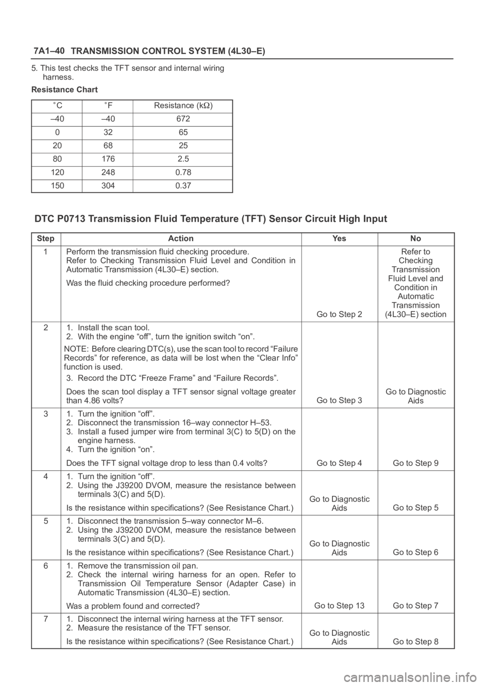
5. This test checks the TFT sensor and internal wiring
harness.
Resistance Chart
CFResistance (k)
–40–40672
03265
206825
801762.5
1202480.78
1503040.37
DTC P0713 Transmission Fluid Temperature (TFT) Sensor Circuit High Input
StepActionYe sNo
1Perform the transmission fluid checking procedure.
Refer to Checking Transmission Fluid Level and Condition in
Automatic Transmission (4L30–E) section.
Was the fluid checking procedure performed?
Go to Step 2
Refer to
Checking
Transmission
Fluid Level and
Condition in
Automatic
Transmission
(4L30–E) section
21. Install the scan tool.
2. With the engine “off”, turn the ignition switch “on”.
NOTE: Before clearing DTC(s), use the scan tool to record “Failure
Records” for reference, as data will be lost when the “Clear Info”
function is used.
3. Record the DTC “Freeze Frame” and “Failure Records”.
Does the scan tool display a TFT sensor signal voltage greater
than 4.86 volts?
Go to Step 3
Go to Diagnostic
Aids
31. Turn the ignition “off”.
2. Disconnect the transmission 16–way connector H–53.
3. Install a fused jumper wire from terminal 3(C) to 5(D) on the
engine harness.
4. Turn the ignition “on”.
Does the TFT signal voltage drop to less than 0.4 volts?
Go to Step 4Go to Step 9
41. Turn the ignition “off”.
2. Using the J39200 DVOM, measure the resistance between
terminals 3(C) and 5(D).
Is the resistance within specifications? (See Resistance Chart.)
Go to Diagnostic
Aids
Go to Step 5
51. Disconnect the transmission 5–way connector M–6.
2. Using the J39200 DVOM, measure the resistance between
terminals 3(C) and 5(D).
Is the resistance within specifications? (See Resistance Chart.)
Go to Diagnostic
Aids
Go to Step 6
61. Remove the transmission oil pan.
2. Check the internal wiring harness for an open. Refer to
Transmission Oil Temperature Sensor (Adapter Case) in
Automatic Transmission (4L30–E) section.
Was a problem found and corrected?
Go to Step 13Go to Step 7
71. Disconnect the internal wiring harness at the TFT sensor.
2. Measure the resistance of the TFT sensor.
Is the resistance within specifications? (See Resistance Chart.)
Go to Diagnostic
Aids
Go to Step 8
Page 2286 of 6000

TRANSMISSION CONTROL SYSTEM (4L30–E)7A1–41
DTC P0713 Transmission Fluid Temperature (TFT) Sensor Circuit High Input (Cont’d)
StepNo Ye s Action
8Replace TFT sensor. Refer to Transmission Oil Temperature
Sensor (Adapter Case) in Automatic Transmission (4L30–E)
section.
Is the replacement complete?
Go to Step 13—
9Check circuit RED/BLK–GRN/RED for an open or short to B+.
Was a problem found?
Go to Step 13Go to Step 10
10Check circuit GRY–GRN for an open.
Was a problem found?
Go to Step 13Go to Step 11
11Check the PCM for faulty or intermittent connections.
Was a problem found?
Go to Step 13Go to Step 12
12Replace the PCM. Refer to Powertrain Control Module (PCM) in
Automatic Transmission (4L30–E) section.
Is the replacement complete?
Go to Step 13—
131. After the repair is complete, use the scan tool to select “DTC”,
then “Clear Info” function and ensure the following conditions
are met:
2. TFT sensor indicates a voltage less than 4.92 volts for 2
seconds.
3. Review the scan tool “DTC Info”.
Has the last test failed or is the current DTC displayed?
Begin diagnosis
again
Go to Step 1
Repair verified
Exit DTC table
Page 2297 of 6000

7A1–52
TRANSMISSION CONTROL SYSTEM (4L30–E)
Conditions For Clearing The DTC/CHECK
TRANS Lamp
The PCM will turn “off” the CHECK TRANS Lamp
after three consecutive ignition cycles without a
failure reported.
The DTC can be cleared from PCM memory by using
a scan tool.
The DTC can also be cleared from memory when the
vehicle has made 40 warmup cycles without a failure
reported.
The PCM will cancel the DTC Actions Taken items
when the fault conditions no longer exist and the
ignition is cycles “off” long enough to power down the
PCM.
Diagnostic Aids
Check for intermittent output speed sensor circuit
problems.
Check for possible incorrect calibration. (PCM part
No., tire specification, and rear axle ratio)
Test Description
The numbers below refer to the step numbers on the
diagnostic chart:
3. This step checks for possible low fluid level causing
slipping resulting in an undefined gear ratio.
4. This step checks for correct gear ratios for
commanded gears.
5. This step checks for low line pressure.
DTC P0730 Transmission Incorrect Gear Ratio
StepActionYe sNo
1Visually inspect the transmission cooling system for fluid leaks.
Refer to Chart 16: Possible Causes of Transmission Fluid
Leaks of Mechanical/Hydraulic Diagnosis Symptoms Index in
Automatic Transmission (4L30–E) section
Was condition found and corrected?
Go to Step 6Go to Step 2
2Refer to Checking Transmission Fluid Level and Condition in
Automatic Transmission (4L30–E) section.
Has transmission fluid checking procedure been performed?
Go to Step 3
Go to Checking
Transmission
Fluid Level and
Condition in
Automatic
Transmission
(4L30–E) section
31. Install the scan tool.
2. Turn the ignition switch to the “on” position.
3. Engine not running.
NOTE: Before clearing DTC(s) use the scan tool to record the
“Failure Records” for reference, as data will be lost when the “Clear
Info” function is used.
4. Record the Failure Record data.
5. Use the scan tool snapshot mode to record transmission gear
ratios.
6. Drive vehicle in transmission gear ranges 1, 2, 3, and D with
the engine speed is greater than 3,500 rpm for 5.5 seconds.
7. Record each transmission gear.
1st:2.73 – 2.99
2nd:1.54 – 1.71
3rd:0.93 – 1.05
4th:0.66 – 0.78
Does commanded gear ratio match ranges as shown?
Refer to
Diagnostic Aids
Go to Step 4
4Perform line pressure check.
Refer to Line Pressure Test in Automatic Transmission
(4L30–E) section.
Was condition found and corrected?
Go to Step 6Go to Step 5
Page 2301 of 6000

7A1–56
TRANSMISSION CONTROL SYSTEM (4L30–E)
DTC P0753 Shift Solenoid A Electrical
D07RW009
Circuit Description
The shift solenoid A is a simple on/off solenoid
located in the main case valve body. The solenoid is
the normally closed type. In second or third gear, the
Powertrain Control Module (PCM) energizes the
solenoid to open a fluid inlet port. When the port is
open, fluid pressure actuates the shift valve.
The solenoid is activated by current. This current is
produced by applying a voltage to one side (the High
side) and a ground to the other side (Low side).
The High Side Driver (HSD) is a circuit of the PCM
that acts as a switch between the solenoids and the
supply voltage. The High side of the solenoid is
permanently supplied with voltage, except in
BACKUP MODE or when ignition is off the HSD is
turned off.
This DTC detects a continuous open or short to ground in
the shift solenoid A circuit or the shift solenoid A. This is a
type “C” DTC.
Conditions For Setting The DTC
Ignition is “on”, Engine “run”.
Battery voltage is between 10 and 16 volts.
The PCM commands the solenoid “on” and the
voltage remains high (B+) or the PCM commands the
solenoid “off” and the voltage remains low (zero
volts).
All conditions met for 0.33 seconds.
Action Taken When The DTC Sets
Maximum line pressure.
Immediate landing to 4th gear.
Inhibit TCC engagement.
The PCM will illuminate the CHECK TRANS Lamp.
Conditions For Clearing The MIL/DTC
The PCM will turn off the CHECK TRANS Lamp after
three consecutive ignition cycles without a failure
reported.
The DTC can be cleared from the PCM history by
using a scan tool.
The DTC will be cleared from history when the vehicle
has achieved 40 warmup cycles without a failure
reported.
The PCM will cancel the DTC default actions when
the fault no longer exists and the ignition is cycled “off”
long enough to power down the PCM.
Diagnostic Aids
Inspect the wiring for poor electrical connection at the
PCM and at the transmission 16–way connector.
Look for possible bent, backed out, deformed or
damaged terminals. Check for weak terminal tension
as we ll. A lso ch eck fo r a ch af e d w ire th at cou l d s ho r t
to bare metal or other wiring. Inspect for a broken wire
inside the insulation.
Page 2304 of 6000

TRANSMISSION CONTROL SYSTEM (4L30–E)7A1–59
DTC P0758 Shift Solenoid B Electrical
D07RW009
Circuit Description
The shift solenoid B is a simple on/off solenoid
located in the main case valve body. It is normally
open. When the port is open, fluid pressure actuates
the shift valve. In first or second gear, the Powertrain
Control Module (PCM) energizes the solenoid to
close a fluid inlet port.
The solenoid is activated by current. This current is
procuded by applying a voltage to one side (the High
side) and a ground to the other side (Low side).
The High Side Driver (HSD) is a circuit of the PCM
that acts as a switch between the solenoids and the
supply voltage. The High side of the solenoid is
permanently supplied with voltage. In BACKUP
MODE or when the ignition is off, the HSD is turned
off.
This DTC detects a continuous open or short to ground in
the shift solenoid B circuit or shift solenoid B. This is a
type “C” DTC.
Conditions For Setting The DTC
Ignition is “on”, Engine “run”.
Battery voltage is between 10 and 16 volts.
The PCM commands the solenoid “on” and the
voltage remains high (B+)or the PCM commands the
solenoid “off” and the voltage remains low (zero
volts).
All conditions met for 0.33 seconds.
Action Taken When The DTC Sets
Fixed to 4th gear.
Maximum line pressure.
Inhibit TCC engagement.
The PCM will illuminate the CHECK TRANS Lamp.
Conditions For Clearing The MIL/DTC
The PCM will turn off the CHECK TRANS Lamp after
three consecutive ignition cycles without a failure
reported.
The DTC can be cleared from the PCM history by
using a scan tool.
The DTC will be cleared from history when the vehicle
has achieved 40 warmup cycles without a failure
reported.
The PCM will cancel the DTC default actions when
the fault no longer exists and the ignition is cycled “off”
long enough to power down the PCM.
Diagnostic Aids
Inspect the wiring for poor electrical connections at
the PCM and at the transmission 16–way connector.
Look for possible bent, backed out, deformed or
damaged terminals. Check for weak terminal tension
as we ll. A lso ch eck fo r a ch af e d w ire th at cou l d s ho r t
to bare metal or other wiring. Inspect for a broken wire
inside the insulation.
Page 2311 of 6000
7A1–66
TRANSMISSION CONTROL SYSTEM (4L30–E)
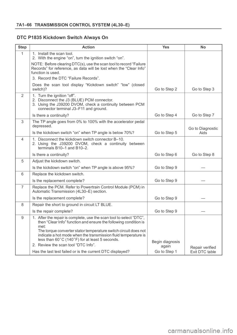
DTC P1835 Kickdown Switch Always On
StepActionYe sNo
11. Install the scan tool.
2. With the engine “on”, turn the ignition switch “on”.
NOTE: Before clearing DTC(s), use the scan tool to record “Failure
Records” for reference, as data will be lost when the “Clear Info”
function is used.
3. Record the DTC “Failure Records”.
Does the scan tool display “Kickdown switch” “low” (closed
switch)?
Go to Step 2Go to Step 3
21. Turn the ignition “off”.
2. Disconnect the J3 (BLUE) PCM connector.
3. Using the J39200 DVOM, check a continuity between PCM
connector terminal J3–F11 and ground.
Is there a continuity?
Go to Step 4Go to Step 7
3The TP angle goes from 0% to 100% with the accelerator pedal
depressed.
Is the kickdown switch “on” when TP angle is below 70%?
Go to Step 5
Go to Diagnostic
Aids
41. Disconnect the kickdown switch connector B–10.
2. Using the J39200 DVOM, check a continuity between
terminals B10–1 and B10–2.
Is there a continuity?
Go to Step 6Go to Step 8
5Adjust the kickdown switch.
Is the kickdown switch “on” when TP angle is above 95%?
Go to Step 9—
6Replace the kickdown switch.
Is the replacement complete?
Go to Step 9—
7Replace the PCM. Refer to Powertrain Control Module (PCM) in
Automatic Transmission (4L30–E) section.
Is the replacement complete?
Go to Step 9—
8Repair the short to ground in circuit LT BLUE.
Is the repair complete?
Go to Step 9—
91. After the repair is complete, use the scan tool to select “DTC”,
then “Clear Info” function and ensure the following condition is
met:
The torque converter stator temperature switch circuit does not
indicate a hot mode when the transmission fluid temperature is
less than 60
C (140F) for at least 5 seconds.
2. Review the scan tool “DTC Info”.
Has the last test failed or is the current DTC displayed?Begin diagnosis
again
Go to Step 1
Repair verified
Exit DTC table
Page 2312 of 6000
TRANSMISSION CONTROL SYSTEM (4L30–E)7A1–67
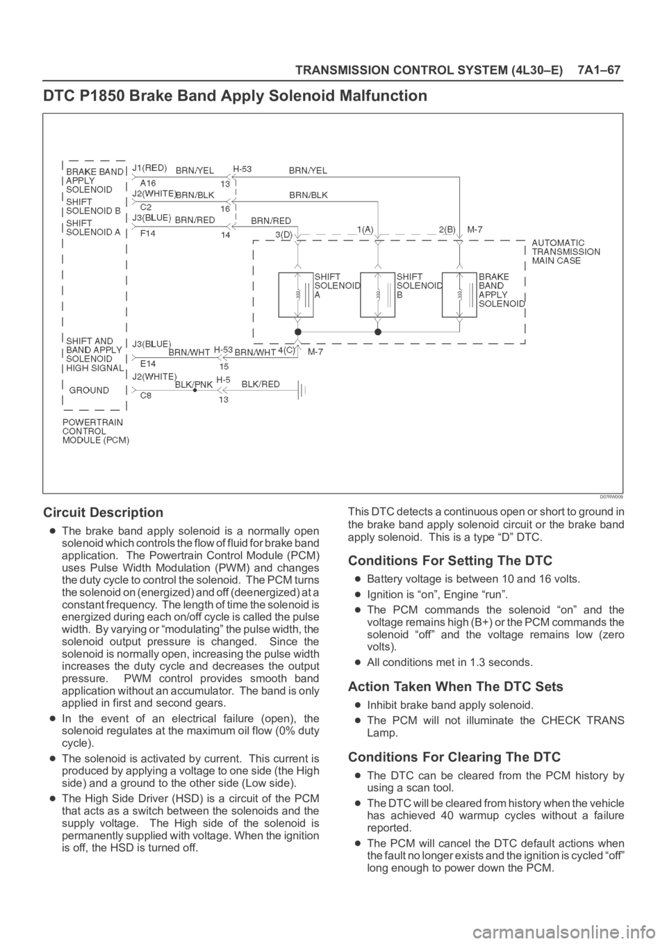
DTC P1850 Brake Band Apply Solenoid Malfunction
D07RW009
Circuit Description
The brake band apply solenoid is a normally open
solenoid which controls the flow of fluid for brake band
application. The Powertrain Control Module (PCM)
uses Pulse Width Modulation (PWM) and changes
the duty cycle to control the solenoid. The PCM turns
the solenoid on (energized) and off (deenergized) at a
constant frequency. The length of time the solenoid is
energized during each on/off cycle is called the pulse
width. By varying or “modulating” the pulse width, the
solenoid output pressure is changed. Since the
solenoid is normally open, increasing the pulse width
increases the duty cycle and decreases the output
pressure. PWM control provides smooth band
application without an accumulator. The band is only
applied in first and second gears.
In the event of an electrical failure (open), the
solenoid regulates at the maximum oil flow (0% duty
cycle).
The solenoid is activated by current. This current is
produced by applying a voltage to one side (the High
side) and a ground to the other side (Low side).
The High Side Driver (HSD) is a circuit of the PCM
that acts as a switch between the solenoids and the
supply voltage. The High side of the solenoid is
permanently supplied with voltage. When the ignition
is off, the HSD is turned off.This DTC detects a continuous open or short to ground in
the brake band apply solenoid circuit or the brake band
apply solenoid. This is a type “D” DTC.
Conditions For Setting The DTC
Battery voltage is between 10 and 16 volts.
Ignition is “on”, Engine “run”.
The PCM commands the solenoid “on” and the
voltage remains high (B+) or the PCM commands the
solenoid “off” and the voltage remains low (zero
volts).
All conditions met in 1.3 seconds.
Action Taken When The DTC Sets
Inhibit brake band apply solenoid.
The PCM will not illuminate the CHECK TRANS
Lamp.
Conditions For Clearing The DTC
The DTC can be cleared from the PCM history by
using a scan tool.
The DTC will be cleared from history when the vehicle
has achieved 40 warmup cycles without a failure
reported.
The PCM will cancel the DTC default actions when
the fault no longer exists and the ignition is cycled “off”
long enough to power down the PCM.
Page 2316 of 6000
TRANSMISSION CONTROL SYSTEM (4L30–E)7A1–71
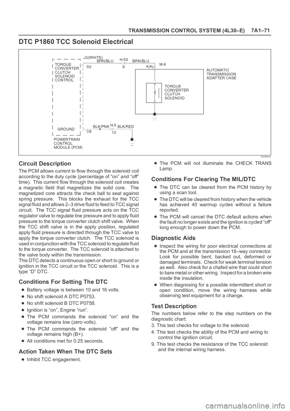
DTC P1860 TCC Solenoid Electrical
D07RW010
Circuit Description
The PCM allows current to flow through the solenoid coil
according to the duty cycle (percentage of “on” and “off”
time). This current flow through the solenoid coil creates
a magnetic field that magnetizes the solid core. The
magnetized core attracts the check ball to seat against
spring pressure. This blocks the exhaust for the TCC
signal fluid and allows 2–3 drive fluid to feed to TCC signal
circuit. The TCC signal fluid pressure acts on the TCC
regulator valve to regulate line pressure and to apply fluid
pressure to the torque converter clutch shift valve. When
the TCC shift valve is in the apply position, regulated
apply fluid pressure is directed through the TCC valve to
apply the torque converter clutch. The TCC solenoid is
used in conjunction with the TCC solenoid to regulate fluid
to the torque converter. The TCC solenoid is attached to
the valve body within the transmission.
This DTC detects a continuous open or short to ground or
ignition in the TCC circuit or the TCC solenoid. This is a
type “D” DTC.
Conditions For Setting The DTC
Battery voltage is between 10 and 16 volts.
No shift solenoid A DTC P0753.
No shift solenoid B DTC P0758.
Ignition is “on”, Engine “run”.
The PCM commands the solenoid “on” and the
voltage remains low (zero volts).
The PCM commands the solenoid “off” and the
voltage remains high (B+).
All conditions met for 0.25 seconds.
Action Taken When The DTC Sets
Inhibit TCC engagement.
The PCM will not illuminate the CHECK TRANS
Lamp.
Conditions For Clearing The MIL/DTC
The DTC can be cleared from the PCM history by
using a scan tool.
The DTC will be cleared from history when the vehicle
has achieved 40 warmup cycles without a failure
reported.
The PCM will cancel the DTC default actions when
the fault no longer exists and the ignition is cycled “off”
long enough to power down the PCM.
Diagnostic Aids
Inspect the wiring for poor electrical connections at
the PCM and at the transmission 16–way connector.
Look for possible bent, backed out, deformed or
damaged terminals. Check for weak terminal tension
as we ll. A lso ch eck fo r a ch af e d w ire th at cou l d s ho r t
to bare metal or other wiring. Inspect for a broken wire
inside the insulation.
When diagnosing for a possible intermittent short or
open condition, move the wiring harness while
observing test equipment for a change.
Test Description
The numbers below refer to the step numbers on the
diagnostic chart:
3. This test checks for voltage to the solenoid.
4. This test checks the ability of the PCM and wiring to
control the ignition circuit.
9. This test checks the resistance of the TCC solenoid
and the internal wiring harness.
Page 4387 of 6000
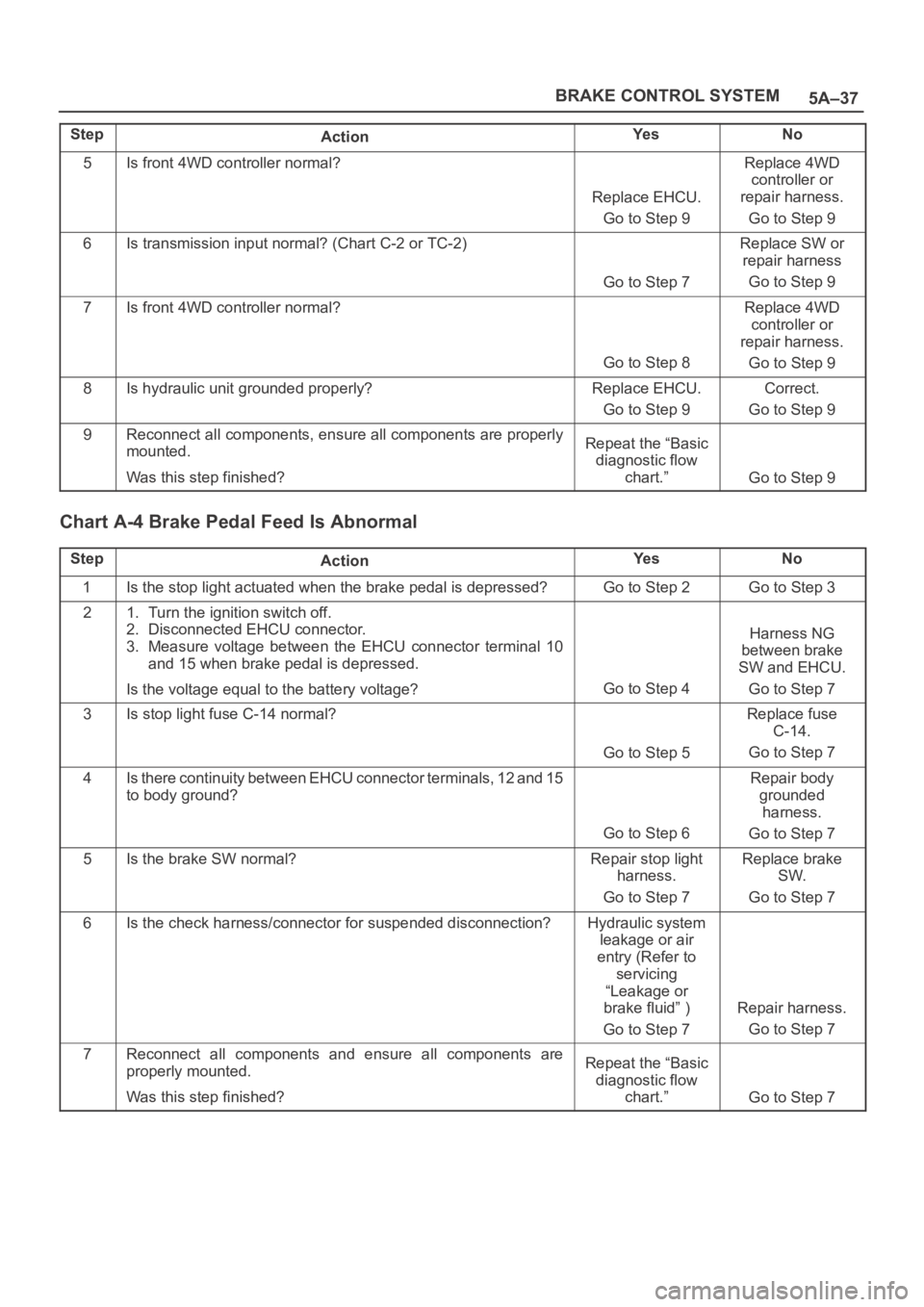
5A–37 BRAKE CONTROL SYSTEM
StepNo Ye s
Action
5Is front 4WD controller normal?
Replace EHCU.
Go to Step 9
Replace 4WD
controller or
repair harness.
Go to Step 9
6Is transmission input normal? (Chart C-2 or TC-2)
Go to Step 7
Replace SW or
repair harness
Go to Step 9
7Is front 4WD controller normal?
Go to Step 8
Replace 4WD
controller or
repair harness.
Go to Step 9
8Is hydraulic unit grounded properly?Replace EHCU.
Go to Step 9Correct.
Go to Step 9
9Reconnect all components, ensure all components are properly
mounted.
Was this step finished?Repeat the “Basic
diagnostic flow
chart.”
Go to Step 9
Chart A-4 Brake Pedal Feed Is Abnormal
StepActionYe sNo
1Is the stop light actuated when the brake pedal is depressed?Go to Step 2Go to Step 3
21. Turn the ignition switch off.
2. Disconnected EHCU connector.
3. Measure voltage between the EHCU connector terminal 10
and 15 when brake pedal is depressed.
Is the voltage equal to the battery voltage?
Go to Step 4
Harness NG
between brake
SW and EHCU.
Go to Step 7
3Is stop light fuse C-14 normal?
Go to Step 5
Replace fuse
C-14.
Go to Step 7
4Is there continuity between EHCU connector terminals, 12 and 15
to body ground?
Go to Step 6
Repair body
grounded
harness.
Go to Step 7
5Is the brake SW normal?Repair stop light
harness.
Go to Step 7Replace brake
SW.
Go to Step 7
6Is the check harness/connector for suspended disconnection?Hydraulic system
leakage or air
entry (Refer to
servicing
“Leakage or
brake fluid” )
Go to Step 7
Repair harness.
Go to Step 7
7Reconnect all components and ensure all components are
properly mounted.
Was this step finished?Repeat the “Basic
diagnostic flow
chart.”
Go to Step 7
Page 4599 of 6000
6B–6
ENGINE COOLING
Draining and Refilling Cooling
System
Before draining the cooling system, inspect the system
and perform any necessary service to ensure that it is
clean, does not leak and is in proper working order. The
engine coolant (EC) level should be between the “MIN”
and “MAX” lines of reserve tank when the engine is cold.
If low, check for leakage and add EC up to the “MAX” line.
There should not be any excessive deposit of rust or
scales around the radiator cap or radiator filler hole, and
the EC should also be free from oil.
Replace the EC if excessively dirty.
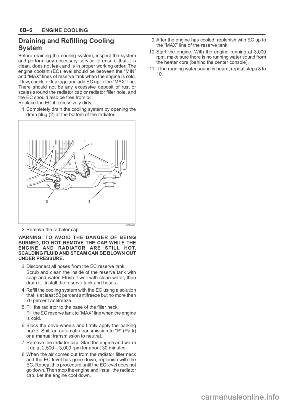
1. Completely drain the cooling system by opening the
drain plug (2) at the bottom of the radiator.
110RW002
2. Remove the radiator cap.
WARNING: TO AVOID THE DANGER OF BEING
BURNED, DO NOT REMOVE THE CAP WHILE THE
ENGINE AND RADIATOR ARE STILL HOT.
SCALDING FLUID AND STEAM CAN BE BLOWN OUT
UNDER PRESSURE.
3. Disconnect all hoses from the EC reserve tank.
Scrub and clean the inside of the reserve tank with
soap and water. Flush it well with clean water, then
drain it. Install the reserve tank and hoses.
4. Refill the cooling system with the EC using a solution
that is at least 50 percent antifreeze but no more than
70 percent antifreeze.
5. Fill the radiator to the base of the filler neck.
Fill the EC reserve tank to “MAX” line when the engine
is cold.
6. Block the drive wheels and firmly apply the parking
brake. Shift an automatic transmission to “P” (Park)
or a manual transmission to neutral.
7. Remove the radiator cap. Start the engine and warm
it up at 2,500
3,000 rpm for about 30 minutes.
8. When the air comes out from the radiator filler neck
and the EC level has gone down, replenish with the
EC. Repeat this procedure until the EC level does not
go down. Then stop the engine and install the radiator
cap. Let the engine cool down.9. After the engine has cooled, replenish with EC up to
the “MAX” line of the reserve tank.
10. Start the engine. With the engine running at 3,000
rpm, make sure there is no running water sound from
the heater core (behind the center console).
11. If the running water sound is heard, repeat steps 8 to
10.