fuel consumption OPEL FRONTERA 1998 Workshop Manual
[x] Cancel search | Manufacturer: OPEL, Model Year: 1998, Model line: FRONTERA, Model: OPEL FRONTERA 1998Pages: 6000, PDF Size: 97 MB
Page 971 of 6000

6A–15
ENGINE MECHANICAL
Condition CorrectionPossible cause
Oil leaking into combustion
chambers due topoor seal in valve
Valve stem oil seal defectiveReplace
chambers due to oor seal in valve
systemValve stem or valve guide wornReplace valve and valve guide
Oil leaking into combustion
chambers due to poor seal in cylinder
t
Cylinders and pistons worn
excessivelyReplace cylinder body assembly and
pistons
partsPiston ring gaps incorrectly
positionedCorrect
Piston rings set with wrong side upCorrect
Piston ring stickingReplace cylinder body assembly and
pistons
Piston ring and ring groove wornReplace pistons and others
Return ports in oil rings cloggedClean piston and replace rings
Positive Crankcase Ventilation
System malfunctioningPositive Crankcase Ventilation Valve
cloggedClean
OthersImproper oil viscosityUse oil of recommended S.A.E.
viscosity
Continuous high speed driving
and/or severe usage such as trailer
towingContinuous high speed operation
and/or severe usage will normally
cause increased oil consumption
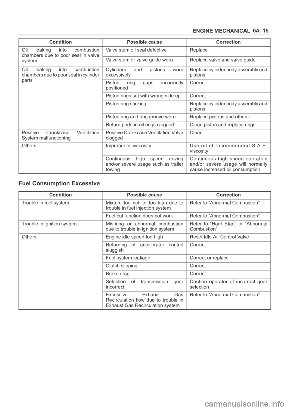
Fuel Consumption Excessive
ConditionPossible causeCorrection
Trouble in fuel systemMixture too rich or too lean due to
trouble in fuel injection systemRefer to “Abnormal Combustion”
Fuel cut function does not workRefer to “Abnormal Combustion”
Trouble in ignition systemMisfiring or abnormal combustion
due to trouble in ignition systemRefer to “Hard Start” or “Abnormal
Combustion”
OthersEngine idle speed too highReset Idle Air Control Valve
Returning of accelerator control
sluggishCorrect
Fuel system leakageCorrect or replace
Clutch slippingCorrect
Brake dragCorrect
Selection of transmission gear
incorrectCaution operator of incorrect gear
selection
Excessive Exhaust Gas
Recirculation flow due to trouble in
Exhaust Gas Recirculation systemRefer to “Abnormal Combustion”
Page 1360 of 6000

6E–243 ENGINE DRIVEABILITY AND EMISSIONS
DTC P1154 – HO2S Transition Time Ratio Bank 2 Sensor 1
StepNo Ye s Va l u e ( s ) Action
12Check for leaks at the exhaust manifold.
Are there leaks at the exhaust manifold?
—Go to Step 13Go to Step 14
13Tighten the bolts to specifications or replace the
manifold if necessary.
Is your action complete?
—Go to Step 2—
14Visually/physically inspect the following items:
Ensure that the Bank 2 HO2S 1 is securely
installed.
Check for corrosion on terminals.
Check terminal tension (at Bank 2 HO2S 1 and at
the PCM).
Check for damaged wiring.
Was a problem found in any of the above areas?
—Go to Step 18Go to Step 15
151. Disconnect Bank 1 HO2S 1.
2. Ignition “ON.”
3. Using a DVM at the PCM side of the HO2S 1
connector, measure the voltage between the high
signal circuit and ground.
Also measure the voltage between the low signal
circuit and ground.
Are both voltages in the specified range?
3-4 V
Go to Step
16
Go to Step 19
161. With Bank 1 HO2S 1 disconnected, jumper the high
and low (PCM side) signal circuits to ground.
2. Ignition “ON.”
3. Using Tech 2, monitor the Bank 2 HO2S 1 voltage.
Does the scan too indicate less than 10 mV and
immediately return to about 450 mV when the jumper is
removed?
—Go to Step 21Go to Step 22
17Replace affected heated oxygen sensors.
NOTE: Before replacing sensors, the cause of the
contamination must be determined and corrected.
Fuel contamination.
Use of improper RTV sealant.
Engine oil/coolant consumption.
Is the action complete?
—Verify repair—
18Repair condition as necessary.
Is the action complete?
—Verify repair—
19Check for faulty PCM connections or terminal damage.
Is the action complete?
—Verify repairGo to Step 20
20Repair open, short or grounded signal circuit.
Is the action complete?
—Verify repair—
Page 2247 of 6000

7A1–2
TRANSMISSION CONTROL SYSTEM (4L30–E)
Service Precaution
WARNING: IF SO EQUIPPED WITH A
SUPPLEMENTAL RESTRAINT SYSTEM (SRS),
REFER TO THE SRS COMPONENT AND WIRING
LOCATION VIEW IN ORDER TO DETERMINE
WHETHER YOU ARE PERFORMING SERVICE ON OR
NEAR THE SRS COMPONENTS OR THE SRS
WIRING. WHEN YOU ARE PERFORMING SERVICE
ON OR NEAR THE SRS COMPONENTS OR THE SRS
WIRING, REFER TO THE SRS SERVICE
INFORMATION. FAILURE TO FOLLOW WARNINGS
COULD RESULT IN POSSIBLE AIR BAG
DEPLOYMENT, PERSONAL INJURY, OR
OTHERWISE UNNEEDED SRS SYSTEM REPAIRS.
CAUTION: Always use the correct fastener in the
proper location. When you replace a fastener, use
ONLY the exact part number for that application.
ISUZU will call out those fasteners that require a
replacement after removal. ISUZU will also call out
the fasteners that require thread lockers or thread
sealant. UNLESS OTHERWISE SPECIFIED, do not
use supplemental coatings (Paints, greases, or other
corrosion inhibitors) on threaded fasteners or
fastener joint interfaces. Generally, such coatings
adversely affect the fastener torque and the joint
clamping force, and may damage the fastener. When
you install fasteners, use the correct tightening
sequence and specifications. Following these
instructions can help you avoid damage to parts and
systems.
General Description
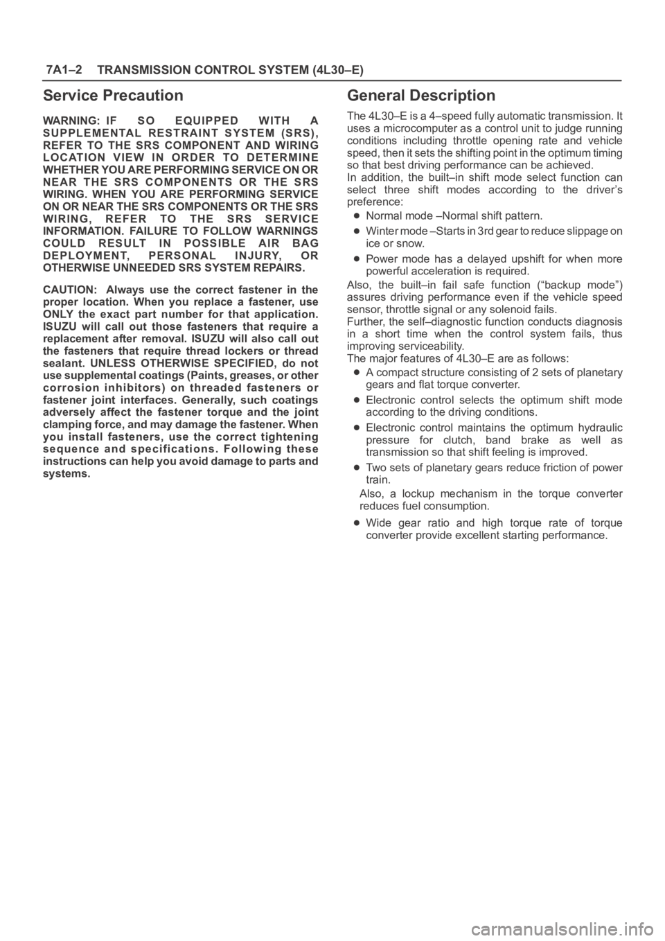
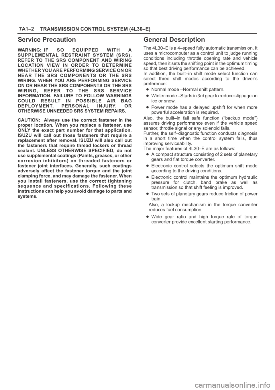
The 4L30–E is a 4–speed fully automatic transmission. It
uses a microcomputer as a control unit to judge running
conditions including throttle opening rate and vehicle
speed, then it sets the shifting point in the optimum timing
so that best driving performance can be achieved.
In addition, the built–in shift mode select function can
select three shift modes according to the driver’s
preference:
Normal mode –Normal shift pattern.
Winter mode –Starts in 3rd gear to reduce slippage on
ice or snow.
Power mode has a delayed upshift for when more
powerful acceleration is required.
Also, the built–in fail safe function (“backup mode”)
assures driving performance even if the vehicle speed
sensor, throttle signal or any solenoid fails.
Further, the self–diagnostic function conducts diagnosis
in a short time when the control system fails, thus
improving serviceability.
The major features of 4L30–E are as follows:
A compact structure consisting of 2 sets of planetary
gears and flat torque converter.
Electronic control selects the optimum shift mode
according to the driving conditions.
Electronic control maintains the optimum hydraulic
pressure for clutch, band brake as well as
transmission so that shift feeling is improved.
Two sets of planetary gears reduce friction of power
train.
Also, a lockup mechanism in the torque converter
reduces fuel consumption.
Wide gear ratio and high torque rate of torque
converter provide excellent starting performance.
Page 4511 of 6000

6A–15
ENGINE MECHANICAL
Condition CorrectionPossible cause
Oil leaking into combustion
chambers due topoor seal in valve
Valve stem oil seal defectiveReplace
chambers due to oor seal in valve
systemValve stem or valve guide wornReplace valve and valve guide
Oil leaking into combustion
chambers due to poor seal in cylinder
t
Cylinders and pistons worn
excessivelyReplace cylinder body assembly and
pistons
partsPiston ring gaps incorrectly
positionedCorrect
Piston rings set with wrong side upCorrect
Piston ring stickingReplace cylinder body assembly and
pistons
Piston ring and ring groove wornReplace pistons and others
Return ports in oil rings cloggedClean piston and replace rings
Positive Crankcase Ventilation
System malfunctioningPositive Crankcase Ventilation Valve
cloggedClean
OthersImproper oil viscosityUse oil of recommended S.A.E.
viscosity
Continuous high speed driving
and/or severe usage such as trailer
towingContinuous high speed operation
and/or severe usage will normally
cause increased oil consumption
Fuel Consumption Excessive
ConditionPossible causeCorrection
Trouble in fuel systemMixture too rich or too lean due to
trouble in fuel injection systemRefer to “Abnormal Combustion”
Fuel cut function does not workRefer to “Abnormal Combustion”
Trouble in ignition systemMisfiring or abnormal combustion
due to trouble in ignition systemRefer to “Hard Start” or “Abnormal
Combustion”
OthersEngine idle speed too highReset Idle Air Control Valve
Returning of accelerator control
sluggishCorrect
Fuel system leakageCorrect or replace
Clutch slippingCorrect
Brake dragCorrect
Selection of transmission gear
incorrectCaution operator of incorrect gear
selection
Excessive Exhaust Gas
Recirculation flow due to trouble in
Exhaust Gas Recirculation systemRefer to “Abnormal Combustion”
Page 4900 of 6000

6E–243 ENGINE DRIVEABILITY AND EMISSIONS
DTC P1154 – HO2S Transition Time Ratio Bank 2 Sensor 1
StepNo Ye s Va l u e ( s ) Action
12Check for leaks at the exhaust manifold.
Are there leaks at the exhaust manifold?
—Go to Step 13Go to Step 14
13Tighten the bolts to specifications or replace the
manifold if necessary.
Is your action complete?
—Go to Step 2—
14Visually/physically inspect the following items:
Ensure that the Bank 2 HO2S 1 is securely
installed.
Check for corrosion on terminals.
Check terminal tension (at Bank 2 HO2S 1 and at
the PCM).
Check for damaged wiring.
Was a problem found in any of the above areas?
—Go to Step 18Go to Step 15
151. Disconnect Bank 1 HO2S 1.
2. Ignition “ON.”
3. Using a DVM at the PCM side of the HO2S 1
connector, measure the voltage between the high
signal circuit and ground.
Also measure the voltage between the low signal
circuit and ground.
Are both voltages in the specified range?
3-4 V
Go to Step
16
Go to Step 19
161. With Bank 1 HO2S 1 disconnected, jumper the high
and low (PCM side) signal circuits to ground.
2. Ignition “ON.”
3. Using Tech 2, monitor the Bank 2 HO2S 1 voltage.
Does the scan too indicate less than 10 mV and
immediately return to about 450 mV when the jumper is
removed?
—Go to Step 21Go to Step 22
17Replace affected heated oxygen sensors.
NOTE: Before replacing sensors, the cause of the
contamination must be determined and corrected.
Fuel contamination.
Use of improper RTV sealant.
Engine oil/coolant consumption.
Is the action complete?
—Verify repair—
18Repair condition as necessary.
Is the action complete?
—Verify repair—
19Check for faulty PCM connections or terminal damage.
Is the action complete?
—Verify repairGo to Step 20
20Repair open, short or grounded signal circuit.
Is the action complete?
—Verify repair—
Page 5821 of 6000

7A–40 AUTOMATIC TRANSMISSION (AW30-40LE)
DTC P0743 (FLASHING CODE 33) TORQUE CONVERTER CLUTCH CONTROL LOCK-UP (ON/
OFF) SOLENOID FA I L U R E ( S L )
D07RY00047Circuit description:
The lock-up solenoid SL of the torque converter clutch
(TCC) controls the lock-up clutch by a signal according to
the lock-up range judgement of the TCM when the
vehicle runs.
This function can improve the fuel consumption to almost
the same extent as the manual transmission. The lock-up
solenoid SL is put into B+ by the TCM, so that the
solenoid is actuated with the result of lock-up.
Fail-safe control:
The TCM controls fail-safe by detecting SL solenoid
fai lu re.
Failure detection:
GND SHORT detection
•When SHORT detection continues for 0.3 sec.
•When SHORT failure detection continues 8 times.
Open detection
•When OPEN detection continues for 0.5 sec.
•When OPEN failure detection continues 8 times.
Contents of control:
At failure detection
• Lock-up control inhibit
• If + B short failure is detected, keeps 1st gear when
the vehicle speed calculated by output revolution
sensor is less than 10km/h to prevent stall.
(Canceled at more than 15km/h)
At failure decision
Executes following items in addition to above control
items at failure detection.
•Stores the failure information in failure-memory.
Conditions of turning “CHECK TRANS” lamp off:
NoneReversion conditions from fail-safe:
When a normal condition is judged by rechecking on the
state of lock-up ON/OFF
Test description:
The following numbers correspond to circled numbers on
the diagnostic char t.
(1) When the key is ON, the voltage between the TCM
connector terminals (C78-12) and (C78-15 or 19) is
1.0 V or less.
(2) When the gear is of the 2nd speed in the D range
and the throttle opening is about 50% at a higher
speed than about 40km/h, the TCM supplies 8 to 16
V, so that the solenoid is actuated with the result of
lock-up.
(3) The resistance range of the solenoid is 11 to 15
.
Diagnostic aids:
In case of faulty connection, open or shorted circuit. to
the TCM terminal (C78-12), DTC P0743 is displayed. A
intermittent failure may be caused by a poor connection,
rubbed through wire insulation or a wire broke inside the
insulation.
Page 5995 of 6000

7A1–2
TRANSMISSION CONTROL SYSTEM (4L30–E)
Service Precaution
WARNING: IF SO EQUIPPED WITH A
SUPPLEMENTAL RESTRAINT SYSTEM (SRS),
REFER TO THE SRS COMPONENT AND WIRING
LOCATION VIEW IN ORDER TO DETERMINE
WHETHER YOU ARE PERFORMING SERVICE ON OR
NEAR THE SRS COMPONENTS OR THE SRS
WIRING. WHEN YOU ARE PERFORMING SERVICE
ON OR NEAR THE SRS COMPONENTS OR THE SRS
WIRING, REFER TO THE SRS SERVICE
INFORMATION. FAILURE TO FOLLOW WARNINGS
COULD RESULT IN POSSIBLE AIR BAG
DEPLOYMENT, PERSONAL INJURY, OR
OTHERWISE UNNEEDED SRS SYSTEM REPAIRS.
CAUTION: Always use the correct fastener in the
proper location. When you replace a fastener, use
ONLY the exact part number for that application.
ISUZU will call out those fasteners that require a
replacement after removal. ISUZU will also call out
the fasteners that require thread lockers or thread
sealant. UNLESS OTHERWISE SPECIFIED, do not
use supplemental coatings (Paints, greases, or other
corrosion inhibitors) on threaded fasteners or
fastener joint interfaces. Generally, such coatings
adversely affect the fastener torque and the joint
clamping force, and may damage the fastener. When
you install fasteners, use the correct tightening
sequence and specifications. Following these
instructions can help you avoid damage to parts and
systems.
General Description
The 4L30–E is a 4–speed fully automatic transmission. It
uses a microcomputer as a control unit to judge running
conditions including throttle opening rate and vehicle
speed, then it sets the shifting point in the optimum timing
so that best driving performance can be achieved.
In addition, the built–in shift mode select function can
select three shift modes according to the driver’s
preference:
Normal mode –Normal shift pattern.
Winter mode –Starts in 3rd gear to reduce slippage on
ice or snow.
Power mode has a delayed upshift for when more
powerful acceleration is required.
Also, the built–in fail safe function (“backup mode”)
assures driving performance even if the vehicle speed
sensor, throttle signal or any solenoid fails.
Further, the self–diagnostic function conducts diagnosis
in a short time when the control system fails, thus
improving serviceability.
The major features of 4L30–E are as follows:
A compact structure consisting of 2 sets of planetary
gears and flat torque converter.
Electronic control selects the optimum shift mode
according to the driving conditions.
Electronic control maintains the optimum hydraulic
pressure for clutch, band brake as well as
transmission so that shift feeling is improved.
Two sets of planetary gears reduce friction of power
train.
Also, a lockup mechanism in the torque converter
reduces fuel consumption.
Wide gear ratio and high torque rate of torque
converter provide excellent starting performance.