radiator OPEL FRONTERA 1998 Manual Online
[x] Cancel search | Manufacturer: OPEL, Model Year: 1998, Model line: FRONTERA, Model: OPEL FRONTERA 1998Pages: 6000, PDF Size: 97 MB
Page 4949 of 6000

6E–292
ENGINE DRIVEABILITY AND EMISSIONS
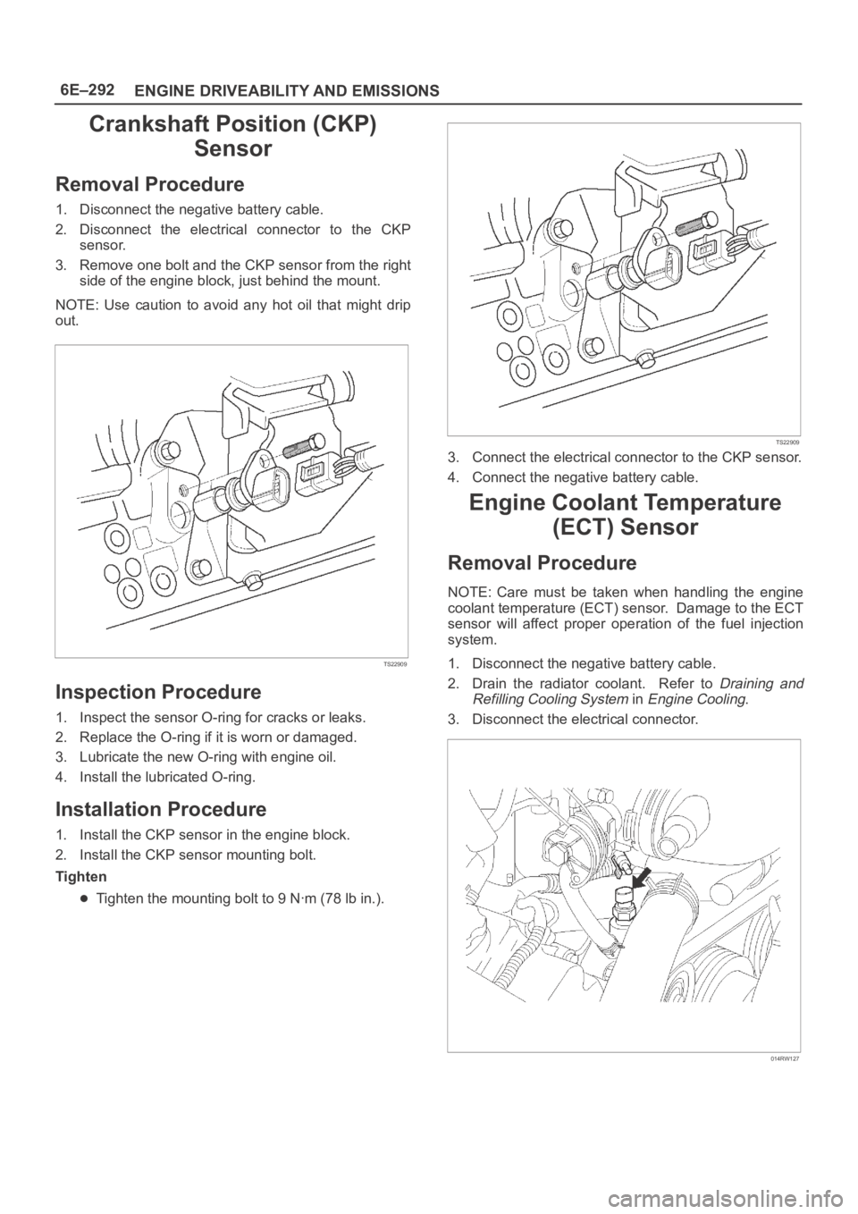
Crankshaft Position (CKP)
Sensor
Removal Procedure
1. Disconnect the negative battery cable.
2. Disconnect the electrical connector to the CKP
sensor.
3. Remove one bolt and the CKP sensor from the right
side of the engine block, just behind the mount.
NOTE: Use caution to avoid any hot oil that might drip
out.
TS22909
Inspection Procedure
1. Inspect the sensor O-ring for cracks or leaks.
2. Replace the O-ring if it is worn or damaged.
3. Lubricate the new O-ring with engine oil.
4. Install the lubricated O-ring.
Installation Procedure
1. Install the CKP sensor in the engine block.
2. Install the CKP sensor mounting bolt.
Tighten
Tighten the mounting bolt to 9 Nꞏm (78 lb in.).
TS22909
3. Connect the electrical connector to the CKP sensor.
4. Connect the negative battery cable.
Engine Coolant Temperature
(ECT) Sensor
Removal Procedure
NOTE: Care must be taken when handling the engine
coolant temperature (ECT) sensor. Damage to the ECT
sensor will affect proper operation of the fuel injection
system.
1. Disconnect the negative battery cable.
2. Drain the radiator coolant. Refer to
Draining and
Refilling Cooling System
in Engine Cooling.
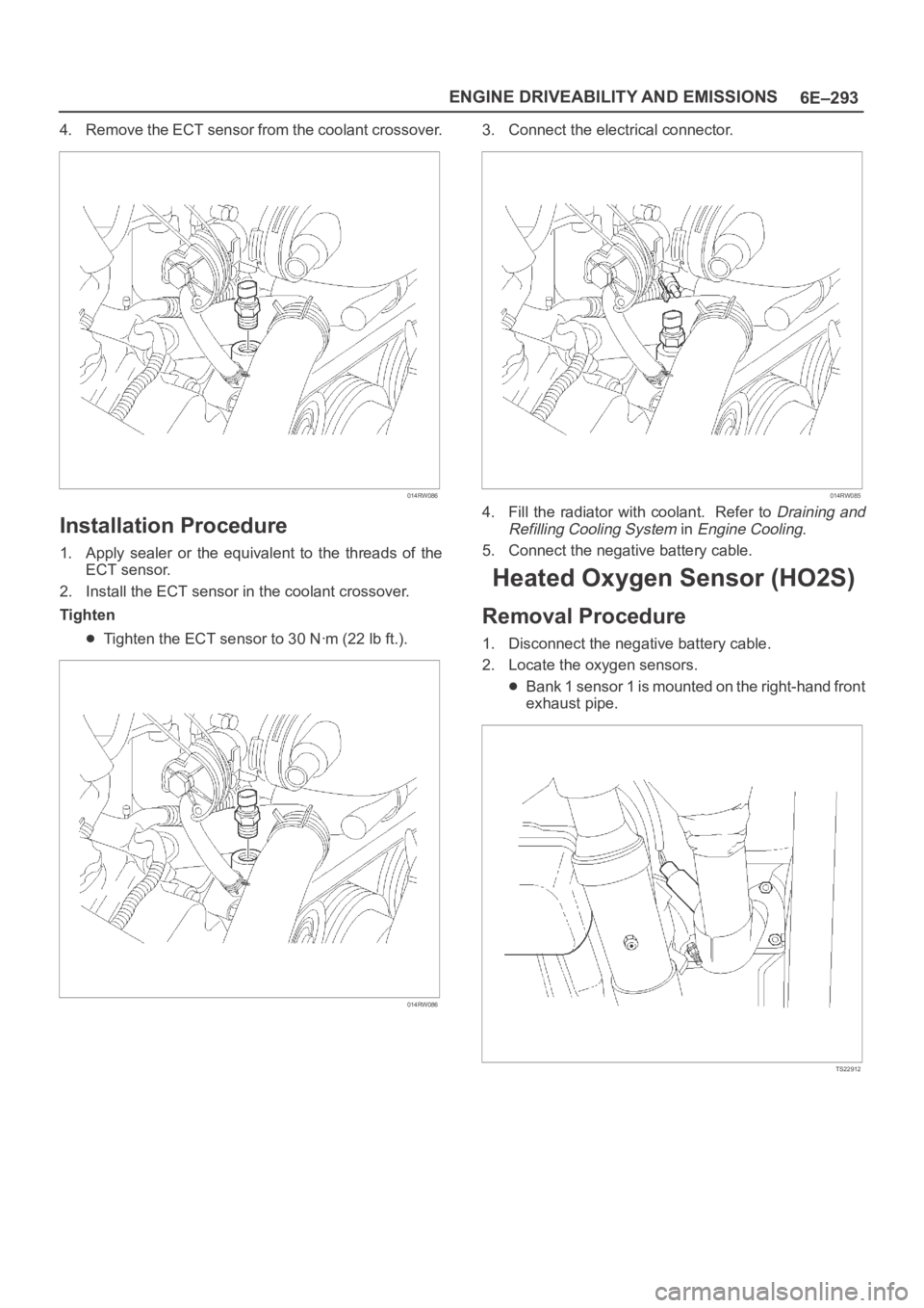
3. Disconnect the electrical connector.
014RW127
Page 4950 of 6000

6E–293 ENGINE DRIVEABILITY AND EMISSIONS
4. Remove the ECT sensor from the coolant crossover.
014RW086
Installation Procedure
1. Apply sealer or the equivalent to the threads of the
ECT sensor.
2. Install the ECT sensor in the coolant crossover.
Tighten
Tighten the ECT sensor to 30 Nꞏm (22 lb ft.).
014RW086
3. Connect the electrical connector.
014RW085
4. Fill the radiator with coolant. Refer to Draining and
Refilling Cooling System
in Engine Cooling.
5. Connect the negative battery cable.
Heated Oxygen Sensor (HO2S)
Removal Procedure
1. Disconnect the negative battery cable.
2. Locate the oxygen sensors.
Bank 1 sensor 1 is mounted on the right-hand front
exhaust pipe.
TS22912
Page 5026 of 6000

6G–7 ENGINE LUBRICATION
Oil Pan and Crankcase
Removal
1. Disconnect battery ground cable.
2. Drain engine oil.
3. Lift vehicle by supporting the frame.
4. Remove front wheels.
5. Remove oil level dipstick from level gauge tube.
6. Remove stone guard.
7. Remove radiator under fan shroud.
8. Remove suspension cross member fixing bolts, 2 pcs
each per side and remove suspension cross member.
9. Remove pitman arm and relay lever assembly, using
the 5–8840–2005–0 remover, remove pitman arm
from the steering unit and remove four fixing bolts for
relay lever assembly.
10. Remove axle housing assembly four fixing bolts from
housing isolator side and mounting bolts from wheel
side. At this time support the axle with a garage jack
and remove axle housing assembly.
11. Remove oil pan fixing bolts.
12. Remove oil pan, using 5–8840–2153–0 sealer cutter,
remove oil pan.
013RS003
13. Remove crankcase fixing bolts.
14. Remove crankcase, using 5–8840–2153–0 sealer
cutter, remove crankcase.
NOTE: Do not deform or damage the flange of oil pan and
crankcase.
Replace the oil pan and/or crankcase if deformed or dam-
aged.
013RS003
Installation
1. Install crankcase.
1. Remove residual sealant, lubricant and moisture
from mounting surface, then dry thoroughly.
2. Properly apply a 4.5 mm (0.7 in) wide bead of
sealant (TB-1207C or equivalent) to mounting
surface of crankcase.
Sealant beat must be continuous.
The crankcase must be installed within 5
minutes after sealant application before the
sealant hardens.
013RW010
Page 5028 of 6000

6G–9 ENGINE LUBRICATION
6. Install suspension cross member and tighten fixing
bolts to the specified torque.
Torque : 78 Nꞏm (8.0 Kgꞏm/58 lb ft)
013RW007
7. Install radiator under fan shroud.
8. Install stone guard.
9. Install engine oil level dipstick.
10. Fill engine oil until full level on engine oil gauge
dipstick.
Page 5277 of 6000

6A – 4 ENGINE MECHANICAL
Engine Cooling
Starting System
Cooling system Coolant forced circulation
Radiator (2 tube in row) Tube type corrugated
Heat radiation capacity J/h (kcal/h) 318 x 10
6(76000)
Heat radiation area m
2(ft2) 15.63 (1.454)
Front area m
2(ft2) 0.309 (2.029)
Dry weight N (kg/lb) 83 (8.5/18.7)
Radiator cap
Valve opening pressure kPa (kg/cm
2psi) 93.3 – 122.7 (0.95 – 1.25/13.5 – 17.8)
Coolant capacity lit (Imp.qt./US qt.) M/T 2.5 (2.2/2.6) A/T 2.4 (2.1/2.5)
Coolant pump Centrifugal impeller type
Pulley ratio 1.2
Coolant total capacity lit (Imp.qt./US qt.) 9.3 (8.2/9.8)
Model HITACHI S14-0
Rating
Voltage V 12
Output kW 2.8
Time sec 30
Number of teeth of pinion 9
Rotating direction (as viewed from pinion) Clockwise
Weight (approx.) N(kg/lb) 49 (5.0/11)
No-load characteristics
Voltage/current V/A 11/160 or less
Speed rpm 4000 or more
Load characteristics
Voltage/current V/A 8.76/300
Torque Nꞏm(kgꞏm/lbꞏft) 7.4 (0.75/5.4) or more
Speed rpm 1700 or more
Locking characteristics
Voltage/current V/A 2.5/1100 or less
Torque Nꞏm(kgꞏm/lbꞏft) 18.6 (1.9/14) or more
Page 5281 of 6000

6A – 8 ENGINE MECHANICAL
Parts Items Service standard Service limit Remarks
Cylinder
Block—
95.421 – 95.450
(3.7567 – 3.7579)0.20 (0.0079) Warpage
(Upper surface of the cylinder block)
Cylinder bore diameter
Parts Items Service standard Service limit Remarks
Thermostat
Radiator cap83 – 87°C
(181 – 189°F)
More than 9.5 (0.374)
at 100°C (212°F)
88.2 – 117.6 kPa
(12.8 –17.0 psi) Valve opening temperature
Valve full open temperature and lift
Valve opening pressure
Engine Coolingmm (in) mm (in)
Page 5283 of 6000

6A – 10 ENGINE MECHANICAL
8. Check the engine oil level and replenish to the
specified level if required.
9. Start the engine and check for oil leakage from the
main oil filter.
FUEL SYSTEM
Fuel filter
Replacement Procedure
1. Loosen the used fuel filter by turning it
counterclockwise with the filter wrench.
Filter Wrench : 5-8840-0203-0
2. Clean the filter cover fitting faces.
This will allow the new fuel filter to seat properly.
3. Apply a light coat of engine oil to the O-ring.
4. Turn the fuel filter until the sealing face comes in
contact with the O-ring.
5. Turn the fuel filter with a filter wrench 2/3 of a turn
until sealed.
Filter Wrench: 5-8840-0203-0Legend
(1) Priming pump
6. Operate the priming pump until the air is discharged
completely from fuel system.
NOTE: The use of an Isuzu genuine fuel filter is
strongly recommended.
COOLING SYSTEM
Coolant Level
Check the coolant level and replenish the radiator
reserve tank as necessary.
If the coolant level falls below the “‘MIN” line, carefully
check the cooling system for leakage. Then add
enough coolant to bring the level up to the “MAX” line.
NOTE: Do not overfill the reserve tank.
012RW112
012RW078
1
012RW111
012RW080
Page 5284 of 6000

ENGINE MECHANICAL 6A – 11
Remove the radiator filler cap only when absolutely
necessary.
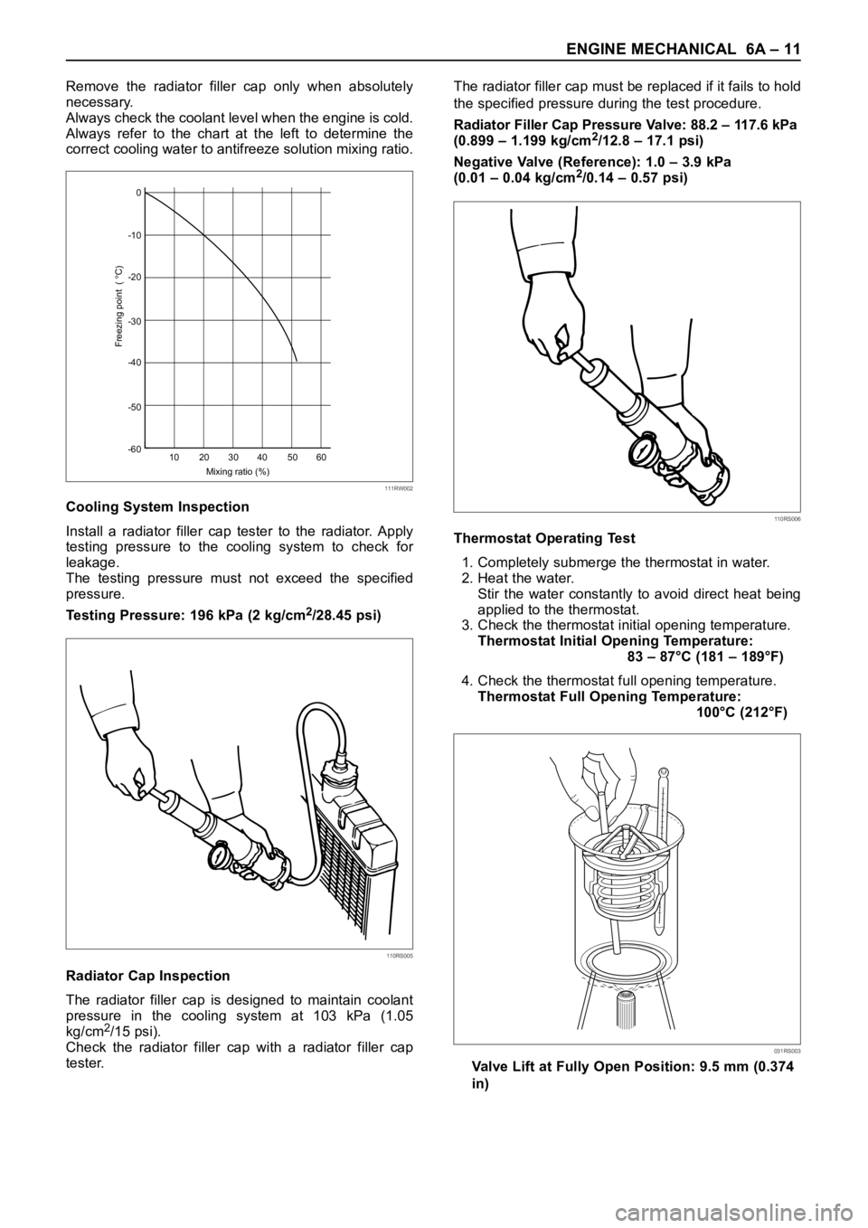
Always check the coolant level when the engine is cold.
Always refer to the chart at the left to determine the
correct cooling water to antifreeze solution mixing ratio.
Cooling System Inspection
Install a radiator filler cap tester to the radiator. Apply
testing pressure to the cooling system to check for
leakage.
The testing pressure must not exceed the specified
pressure.
Testing Pressure: 196 kPa (2 kg/cm
2/28.45 psi)
Radiator Cap Inspection
The radiator filler cap is designed to maintain coolant
pressure in the cooling system at 103 kPa (1.05
kg/cm
2/15 psi).
Check the radiator filler cap with a radiator filler cap
tester.The radiator filler cap must be replaced if it fails to hold
the specified pressure during the test procedure.
Radiator Filler Cap Pressure Valve: 88.2 – 117.6 kPa
(0.899 – 1.199 kg/cm
2/12.8 – 17.1 psi)
Negative Valve (Reference): 1.0 – 3.9 kPa
(0.01 – 0.04 kg/cm
2/0.14 – 0.57 psi)
Thermostat Operating Test
1. Completely submerge the thermostat in water.
2. Heat the water.
Stir the water constantly to avoid direct heat being
applied to the thermostat.
3. Check the thermostat initial opening temperature.
Thermostat Initial Opening Temperature:
83 – 87°C (181 – 189°F)
4. Check the thermostat full opening temperature.
Thermostat Full Opening Temperature:
100°C (212°F)
Valve Lift at Fully Open Position: 9.5 mm (0.374
in)0
-10
-20
-30
-40
-50
-60
10 20 30
Mixing ratio (%)
Freezing point (
C)
40 50 60
111RW002
110RS005
110RS006
031RS003
Page 5299 of 6000

6A – 26 ENGINE MECHANICAL
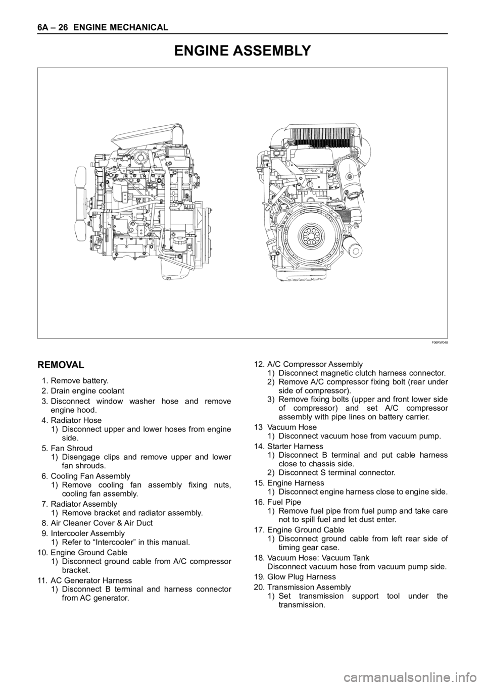
ENGINE ASSEMBLY
F06RW048
REMOVAL
1. Remove battery.
2. Drain engine coolant
3. Disconnect window washer hose and remove
engine hood.
4. Radiator Hose
1) Disconnect upper and lower hoses from engine
side.
5. Fan Shroud
1) Disengage clips and remove upper and lower
fan shrouds.
6. Cooling Fan Assembly
1) Remove cooling fan assembly fixing nuts,
cooling fan assembly.
7. Radiator Assembly
1) Remove bracket and radiator assembly.
8. Air Cleaner Cover & Air Duct
9. Intercooler Assembly
1) Refer to “Intercooler” in this manual.
10. Engine Ground Cable
1) Disconnect ground cable from A/C compressor
bracket.
11. AC Generator Harness
1) Disconnect B terminal and harness connector
from AC generator.12. A/C Compressor Assembly
1) Disconnect magnetic clutch harness connector.
2) Remove A/C compressor fixing bolt (rear under
side of compressor).
3) Remove fixing bolts (upper and front lower side
of compressor) and set A/C compressor
assembly with pipe lines on battery carrier.
13 Vacuum Hose
1) Disconnect vacuum hose from vacuum pump.
14. Starter Harness
1) Disconnect B terminal and put cable harness
close to chassis side.
2) Disconnect S terminal connector.
15. Engine Harness
1) Disconnect engine harness close to engine side.
16. Fuel Pipe
1) Remove fuel pipe from fuel pump and take care
not to spill fuel and let dust enter.
17. Engine Ground Cable
1) Disconnect ground cable from left rear side of
timing gear case.
18. Vacuum Hose: Vacuum Tank
Disconnect vacuum hose from vacuum pump side.
19. Glow Plug Harness
20. Transmission Assembly
1) Set transmission support tool under the
transmission.
Page 5300 of 6000

ENGINE MECHANICAL 6A – 27
2) Remove transmission rear mount.
3) Remove transmission fixing bolt from rear of
engine assembly except two bolts.
4) Carefully hang up engine assembly with a hoist.
5) Remove remaining two transmission fixing bolts.
6) Remove transmission assembly.
7) Remove heater hose.
8) Disconnect wire harness connector for shift on
the fly.
9) Remove vacuum hose.
21. Prepare Engine Stand
22. Engine Assembly
1) Remove engine mount fixing bolts.
2) Carefully hang up the engine assembly.
3) Take out the engine assembly making sure not
to damage the brake oil pipe and other pipe etc.
INSTALLATION
1. Engine assembly
1) Install engine in mounting position by using
hoist.
2. Transmission Assembly
1) Refer to transmission installation steps in
section 7.
3. Engine Mounting
1) After all fixing bolts (left: two bolts, rights: two
bolts) were inserted in every hole, tighten fixing
bolts to the specified torque.
Torque: 40 Nꞏm (4 kgꞏm/29 lbꞏft)
4. Glow Plug Harness
5. Vacuum Hose
1) Connect Vacuum Hose to Vacuum Pump
6. Engine Ground Cable
7. Fuel Pipe
1) Install fuel pipe to fuel pump.
8. Engine Harness
9. Starter Harness
10. A/C Compressor Assembly
1) Tighten temporarily the fixing bolts (upper and
front lower sides of compressor.)
2) Tighten fixing bolt (rear under side of
compressor) to the specified torque.
3) Tighten fixing bolts (front upper and lower sides
of compressor) to the specified torque.
Torque: 40 Nꞏm (4 kgꞏm/29 lbꞏft)Legend
(1) Tensioner
(2) Bolt
(3) Bracket
(4) A/C compressor
(5) Bolt
11. A.C Generator Harness
12. Engine Ground Cable
1) Tighten ground cable to A/C compressor
bracket.
13. Air Cleaner cover & Duct
14. Intercooler Assembly
1) Refer to “Intercooler” in this manual.
15. Radiator Assembly
1) Install rubber cushion in under left and right part
of radiator and position radiator.
2) Fix radiator with bracket.
16. Cooling Fan Assembly
1) Install cooling fan assembly and tighten fixing
bolts to the specified torque.
Torque: 8 Nꞏm (0.8 kgꞏm/5.8 lb ft)
17. Fan Shroud
18. Radiator Hose
1) Connect upper and lower hose to engine side.
2) Pour coolant into radiator.
19. Install battery.
20. Connect window washer hose and install engine
hood.
1
2
3
4
5
F06RW054