air filter OPEL FRONTERA 1998 Workshop Manual
[x] Cancel search | Manufacturer: OPEL, Model Year: 1998, Model line: FRONTERA, Model: OPEL FRONTERA 1998Pages: 6000, PDF Size: 97 MB
Page 537 of 6000

4B1–4
DRIVE LINE CONTROL SYSTEM (SHIFT ON THE FLY)
Inspection and Repair
Va c u u m P i p i n g
C04RW016
1. Pull out the Hose A in figure and install a vacuum
gauge.
2. Plug up Hose B in figure to prevent the leak of
vacuum.
3. Start the engine and measure vacuum 2 or 3 minutes
afterward.
4. Repeat 1) and 2) but with Hose A plugged and Hose B
pulled out.
5. If vacuum measures –400mmHg, or if it shows a
sudden drop immediately after engine stop, inspect
the hose, tank, and pipe for damage.
NOTE: Be careful not to permit the entry of dust and
water during inspection.
6. Pull out Hose D in above illustration.
7. Plug Hose E in above illustration.
8. Make sure that Hose D in above illustration is under
atmospheric pressure.
9. Pull out Hose E and plug Hose D, and make sure that
Hose E is under atmospheric pressure.
10. If Check 8) or 9) has revealed stoppage, check and
see that there is no bend, foreign matter in the hose or
in the filter. If there is trouble, repair or replace.Check Valve
C04RS004
1. Apply vacuum from the orange colored side(1).
Vacuum:–400mmHg
2. Check leakage of vacuum.
3. Make sure that vacuum cannot be applied from the
black colored side(2).
Page 566 of 6000
4B1–33 DRIVE LINE CONTROL SYSTEM (SHIFT ON THE FLY)
Inspection and Repair
Va c u u m P i p i n g
C04RW014
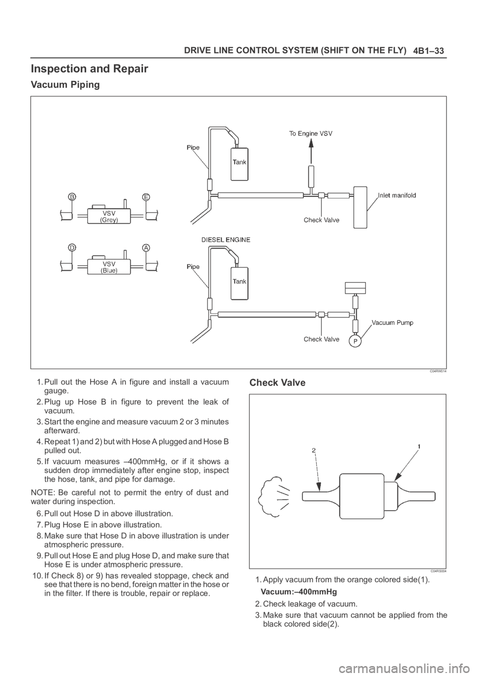
1. Pull out the Hose A in figure and install a vacuum
gauge.
2. Plug up Hose B in figure to prevent the leak of
vacuum.
3. Start the engine and measure vacuum 2 or 3 minutes
afterward.
4. Repeat 1) and 2) but with Hose A plugged and Hose B
pulled out.
5. If vacuum measures –400mmHg, or if it shows a
sudden drop immediately after engine stop, inspect
the hose, tank, and pipe for damage.
NOTE: Be careful not to permit the entry of dust and
water during inspection.
6. Pull out Hose D in above illustration.
7. Plug Hose E in above illustration.
8. Make sure that Hose D in above illustration is under
atmospheric pressure.
9. Pull out Hose E and plug Hose D, and make sure that
Hose E is under atmospheric pressure.
10. If Check 8) or 9) has revealed stoppage, check and
see that there is no bend, foreign matter in the hose or
in the filter. If there is trouble, repair or replace.Check Valve
C04RS004
1. Apply vacuum from the orange colored side(1).
Vacuum:–400mmHg
2. Check leakage of vacuum.
3. Make sure that vacuum cannot be applied from the
black colored side(2).
Page 959 of 6000
6A–3
ENGINE MECHANICAL
General Description
Engine Cleanliness And Care
An automobile engine is a combination of many
machined, honed, polished and lapped surfaces with
tolerances that are measured in the thousandths of a
millimeter (ten thousandths of an inch). Accordingly,
when any internal engine parts are serviced, care and
cleanliness are important. Throughout this section, it
should be understood that proper cleaning and protection
of machined surfaces and friction areas is part of the
repair procedure. This is considered standard shop
practice even if not specifically stated.
A liberal coating of engine oil should be applied to all
friction areas during assembly to protect and lubricate
the surfaces on initial operation.
Whenever valve train components, pistons, piston
rings, connecting rods, rod bearings, and crankshaft
journal bearings are removed for service, they should
be retained in order.
At the time of installation, they should be installed in
the same locations and with the same mating
surfaces as when removed.
Battery cables should be disconnected before any
major work is performed on the engine. Failure to
disconnect cables may result in damage to wire
harness or other electrical parts.
The six cylinders of this engine are identified by
numbers; Right side cylinders 1, 3 and 5, Left side
cylinders 2, 4 and 6, as counted from crankshaft
pulley side to flywheel side.
General Information on Engine Service
The following information on engine service should be
noted carefully, as it is important in preventing damage
and contributing to reliable engine performance:
When raising or supporting the engine for any reason,
do not use a jack under the oil pan. Due to the small
clearance between the oil pan and the oil pump
strainer, jacking against the oil pan may cause
damage to the oil pick–up unit.
The 12–volt electrical system is capable of damaging
circuits. When performing any work where electrical
terminals could possibly be grounded, the ground
cable of the battery should be disconnected at the
battery.
Any time the intake air duct or air cleaner is removed,
the intake opening should be covered. This will
protect against accidental entrance of foreign
material into the cylinder which could cause extensive
damage when the engine is started.
Cylinder Block
The cylinder block is made of aluminum die–cast casting
for 75
V–type six cylinders. It has a rear plate integrated
structure and employs a deep skint. The cylinder liner is
cast and the liner inner diameter and crankshaft journal
diameter are classified into grades. The crankshaft is
supported by four bearings of which width of No.3 bearing
on the body side is different in order to support the thrust
bearing. The bearing cap is made of nodular cast iron and
each bearing cap uses four bolts and two side bolts.
Cylinder Head
The cylinder head, made of aluminum alloy casting
employs a pent–roof type combustion chamber with a
spark plug in the center. The intake and exhaust valves
are placed in V–type design. The ports are cross–flow
type.
Va l v e Tr a i n
Intake and exhaust camshaft on the both side of banks
are driven through an camshaft drive gear by timing belt.
The valves are operated by the camshaft and the valve
clearance is adjusted to select suitable thickness shim.
Intake Manifold
The intake manifold system is composed of the aluminum
cast common chamber and intake manifold attached with
six fuel injectors.
Exhaust Manifold
The exhaust manifold is made of nodular cast iron.
Pistons and Connecting Rods
Aluminum pistons are used after selecting the grade that
meets the cylinder bore diameter. Each piston has two
compression rings and one oil ring. The piston pin is made
of chromium steel is offset 1mm toward the thrust side,
and the thrust pressure of piston to the cylinder wall varies
gradually as the piston travels. The connecting rods are
made of forged steel. The connecting rod bearings are
graded for correct seze selection.
Crankshaft and Bearings
The crankshaft is made of Ductile cast–iron. Pins and
journals are graded for correct size selection for their
bearing.
Engine Lubrication
The oil discharged by a trochoid–type oil pump driven by
the crankshaft is fed through full–flow oil filter and to the oil
gallery provided under the crankshaft bearing cap. The oil
is then led to the crankshaft journals and cylinder head.
The crank pins are lubricated with oil from crankshaft
journals through oil holes. Also, an oil jet is fed to each
cylinder from crankshaft juornals on the connecting rod
for piston cleaning. The oil pan flange is dealed with liquid
packing only; do not deform or damage the flange surface
during removal or installation.
Page 963 of 6000
6A–7
ENGINE MECHANICAL
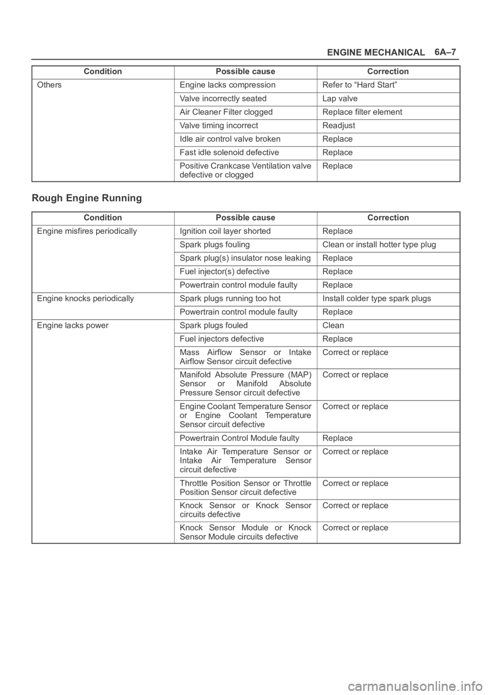
Condition CorrectionPossible cause
OthersEngine lacks compressionRefer to “Hard Start”
Valve incorrectly seatedLap valve
Air Cleaner Filter cloggedReplace filter element
Valve timing incorrectReadjust
Idle air control valve brokenReplace
Fast idle solenoid defectiveReplace
Positive Crankcase Ventilation valve
defective or cloggedReplace
Rough Engine Running
ConditionPossible causeCorrection
Engine misfires periodicallyIgnition coil layer shortedReplace
Spark plugs foulingClean or install hotter type plug
Spark plug(s) insulator nose leakingReplace
Fuel injector(s) defectiveReplace
Powertrain control module faultyReplace
Engine knocks periodicallySpark plugs running too hotInstall colder type spark plugs
Powertrain control module faultyReplace
Engine lacks powerSpark plugs fouledClean
Fuel injectors defectiveReplace
Mass Airflow Sensor or Intake
Airflow Sensor circuit defectiveCorrect or replace
Manifold Absolute Pressure (MAP)
Sensor or Manifold Absolute
Pressure Sensor circuit defectiveCorrect or replace
Engine Coolant Temperature Sensor
or Engine Coolant Temperature
Sensor circuit defectiveCorrect or replace
Powertrain Control Module faultyReplace
Intake Air Temperature Sensor or
Intake Air Temperature Sensor
circuit defectiveCorrect or replace
Throttle Position Sensor or Throttle
Position Sensor circuit defectiveCorrect or replace
Knock Sensor or Knock Sensor
circuits defectiveCorrect or replace
Knock Sensor Module or Knock
Sensor Module circuits defectiveCorrect or replace
Page 964 of 6000
6A–8
ENGINE MECHANICAL
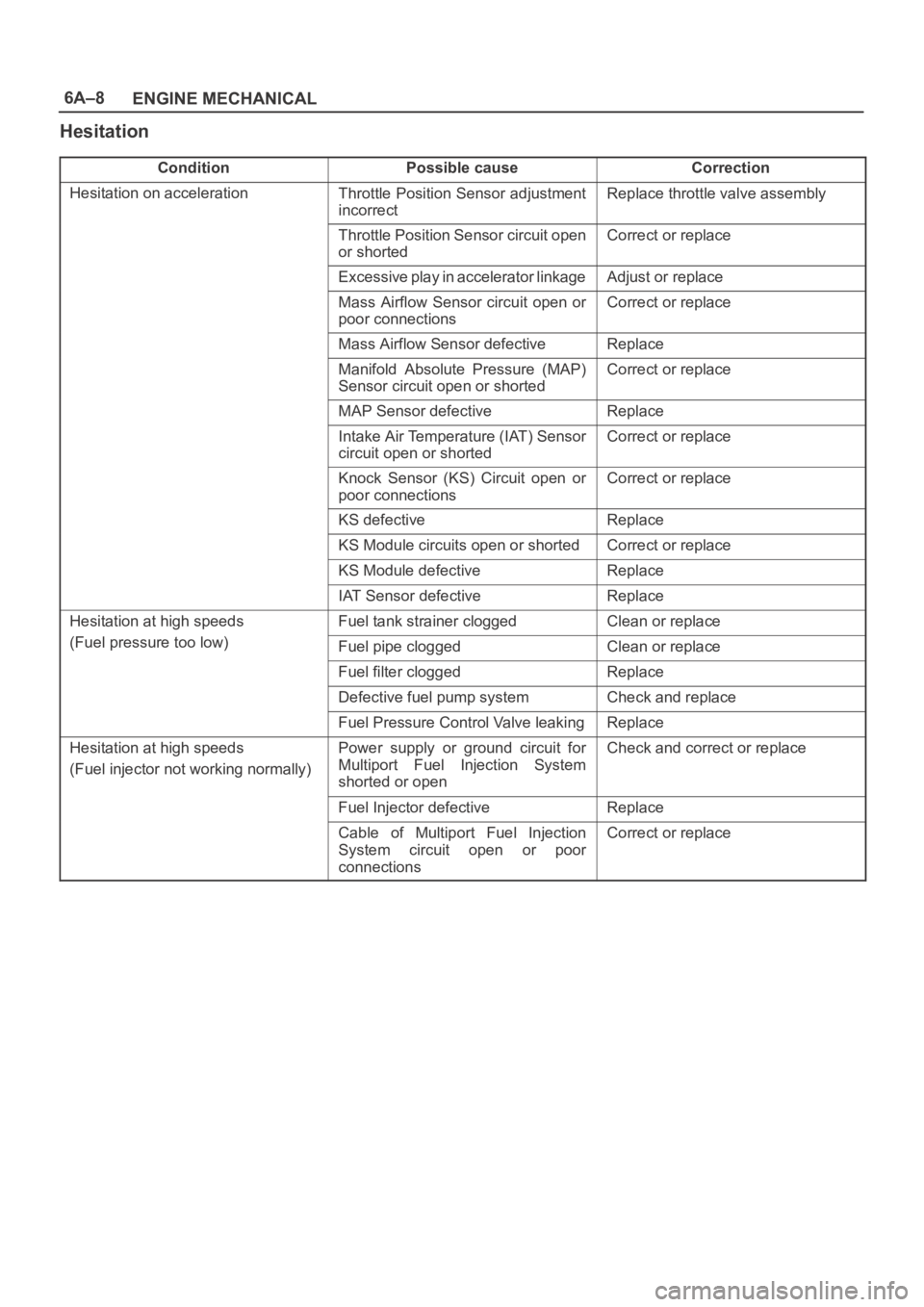
Hesitation
ConditionPossible causeCorrection
Hesitation on accelerationThrottle Position Sensor adjustment
incorrectReplace throttle valve assembly
Throttle Position Sensor circuit open
or shortedCorrect or replace
Excessive play in accelerator linkageAdjust or replace
Mass Airflow Sensor circuit open or
poor connectionsCorrect or replace
Mass Airflow Sensor defectiveReplace
Manifold Absolute Pressure (MAP)
Sensor circuit open or shortedCorrect or replace
MAP Sensor defectiveReplace
Intake Air Temperature (IAT) Sensor
circuit open or shortedCorrect or replace
Knock Sensor (KS) Circuit open or
poor connectionsCorrect or replace
KS defectiveReplace
KS Module circuits open or shortedCorrect or replace
KS Module defectiveReplace
IAT Sensor defectiveReplace
Hesitation at high speedsFuel tank strainer cloggedClean or replace
(Fuel pressure too low)Fuel pipe cloggedClean or replace
Fuel filter cloggedReplace
Defective fuel pump systemCheck and replace
Fuel Pressure Control Valve leakingReplace
Hesitation at high speeds
(Fuel injector not working normally)Power supply or ground circuit for
Multiport Fuel Injection System
shorted or openCheck and correct or replace
Fuel Injector defectiveReplace
Cable of Multiport Fuel Injection
System circuit open or poor
connectionsCorrect or replace
Page 965 of 6000
6A–9
ENGINE MECHANICAL
Condition CorrectionPossible cause
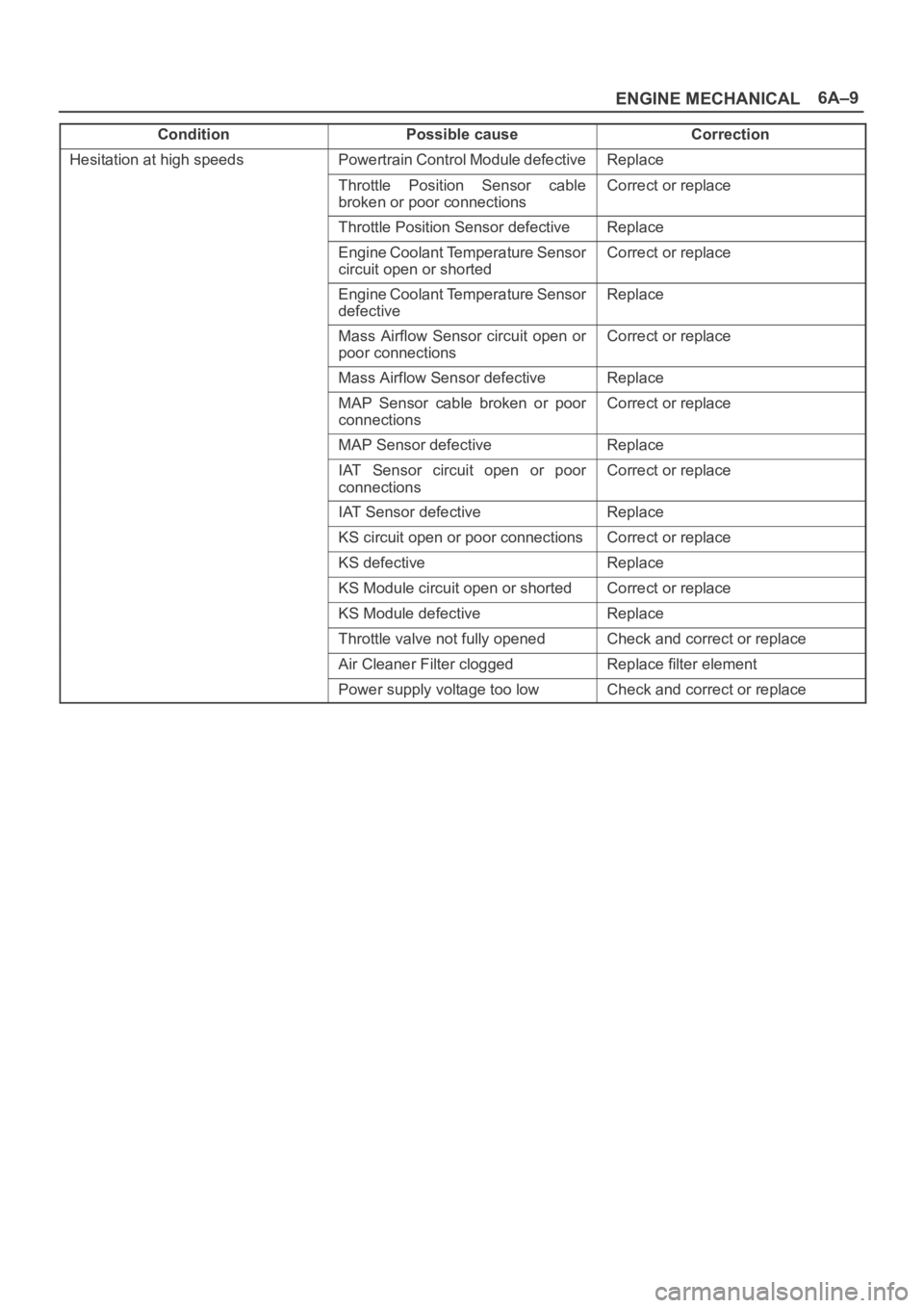
Hesitation at high speedsPowertrain Control Module defectiveReplace
Throttle Position Sensor cable
broken or poor connectionsCorrect or replace
Throttle Position Sensor defectiveReplace
Engine Coolant Temperature Sensor
circuit open or shortedCorrect or replace
Engine Coolant Temperature Sensor
defectiveReplace
Mass Airflow Sensor circuit open or
poor connectionsCorrect or replace
Mass Airflow Sensor defectiveReplace
MAP Sensor cable broken or poor
connectionsCorrect or replace
MAP Sensor defectiveReplace
IAT Sensor circuit open or poor
connectionsCorrect or replace
IAT Sensor defectiveReplace
KS circuit open or poor connectionsCorrect or replace
KS defectiveReplace
KS Module circuit open or shortedCorrect or replace
KS Module defectiveReplace
Throttle valve not fully openedCheck and correct or replace
Air Cleaner Filter cloggedReplace filter element
Power supply voltage too lowCheck and correct or replace
Page 966 of 6000
6A–10
ENGINE MECHANICAL
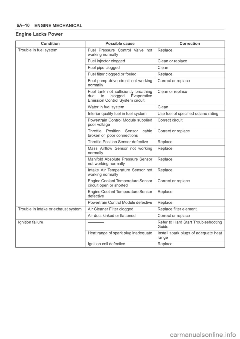
Engine Lacks Power
ConditionPossible causeCorrection
Trouble in fuel systemFuel Pressure Control Valve not
working normallyReplace
Fuel injector cloggedClean or replace
Fuel pipe cloggedClean
Fuel filter clogged or fouledReplace
Fuel pump drive circuit not working
normallyCorrect or replace
Fuel tank not sufficiently breathing
due to clogged Evaporative
Emission Control System circuitClean or replace
Water in fuel systemClean
Inferior quality fuel in fuel systemUse fuel of specified octane rating
Powertrain Control Module supplied
poor voltageCorrect circuit
Throttle Position Sensor cable
broken or poor connectionsCorrect or replace
Throttle Position Sensor defectiveReplace
Mass Airflow Sensor not working
normallyReplace
Manifold Absolute Pressure Sensor
not working normallyReplace
Intake Air Temperature Sensor not
working normallyReplace
Engine Coolant Temperature Sensor
circuit open or shortedCorrect or replace
Engine Coolant Temperature Sensor
defectiveReplace
Powertrain Control Module defectiveReplace
Trouble in intake or exhaust systemAir Cleaner Filter cloggedReplace filter element
Air duct kinked or flattenedCorrect or replace
Ignition failure————Refer to Hard Start Troubleshooting
Guide
Heat range of spark plug inadequateInstall spark plugs of adequate heat
range
Ignition coil defectiveReplace
Page 969 of 6000
6A–13
ENGINE MECHANICAL
Condition CorrectionPossible cause
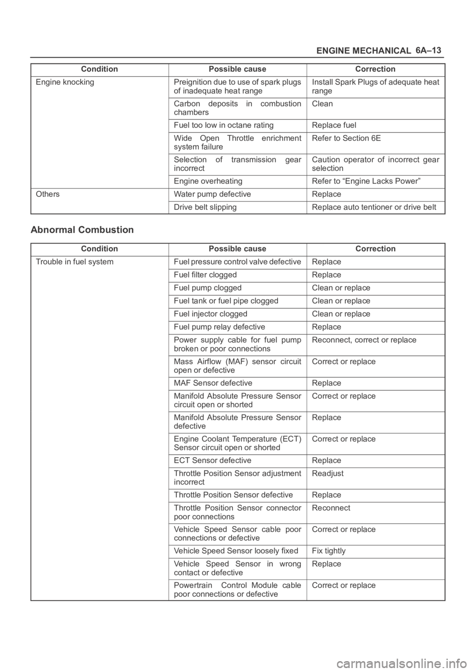
Engine knockingPreignition due to use of spark plugs
of inadequate heat rangeInstall Spark Plugs of adequate heat
range
Carbon deposits in combustion
chambersClean
Fuel too low in octane ratingReplace fuel
Wide Open Throttle enrichment
system failureRefer to Section 6E
Selection of transmission gear
incorrectCaution operator of incorrect gear
selection
Engine overheatingRefer to “Engine Lacks Power”
OthersWater pump defectiveReplace
Drive belt slippingReplace auto tentioner or drive belt
Abnormal Combustion
ConditionPossible causeCorrection
Trouble in fuel systemFuel pressure control valve defectiveReplace
Fuel filter cloggedReplace
Fuel pump cloggedClean or replace
Fuel tank or fuel pipe cloggedClean or replace
Fuel injector cloggedClean or replace
Fuel pump relay defectiveReplace
Power supply cable for fuel pump
broken or poor connectionsReconnect, correct or replace
Mass Airflow (MAF) sensor circuit
open or defectiveCorrect or replace
MAF Sensor defectiveReplace
Manifold Absolute Pressure Sensor
circuit open or shortedCorrect or replace
Manifold Absolute Pressure Sensor
defectiveReplace
Engine Coolant Temperature (ECT)
Sensor circuit open or shortedCorrect or replace
ECT Sensor defectiveReplace
Throttle Position Sensor adjustment
incorrectReadjust
Throttle Position Sensor defectiveReplace
Throttle Position Sensor connector
poor connectionsReconnect
Vehicle Speed Sensor cable poor
connections or defectiveCorrect or replace
Vehicle Speed Sensor loosely fixedFix tightly
Vehicle Speed Sensor in wrong
contact or defectiveReplace
Powertrain Control Module cable
poor connections or defectiveCorrect or replace
Page 1068 of 6000
6C–1
ENGINE FUEL
ENGINE
ENGINE FUEL
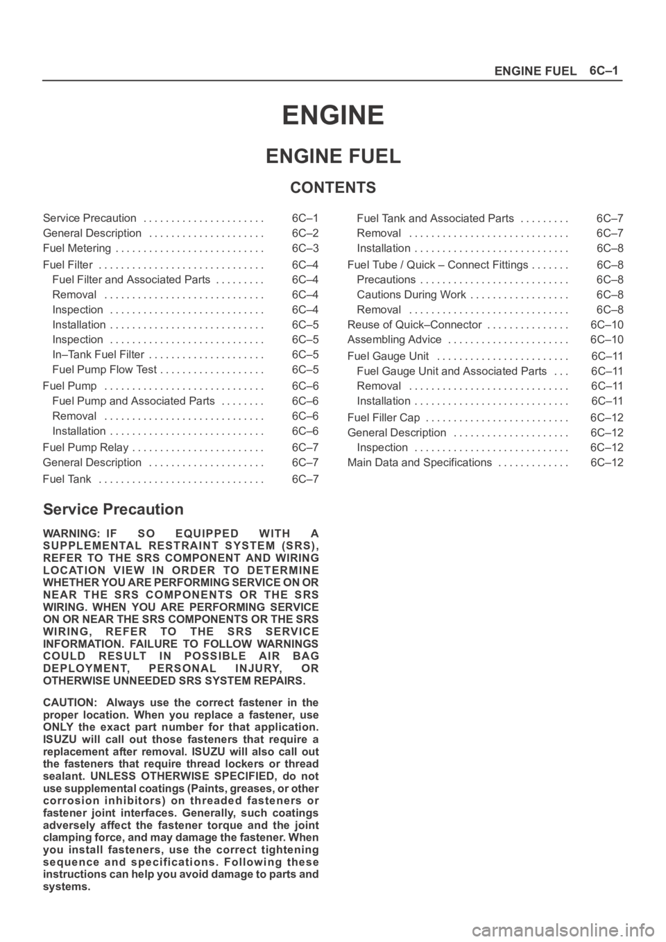
CONTENTS
Service Precaution 6C–1. . . . . . . . . . . . . . . . . . . . . .
General Description 6C–2. . . . . . . . . . . . . . . . . . . . .
Fuel Metering 6C–3. . . . . . . . . . . . . . . . . . . . . . . . . . .
Fuel Filter 6C–4. . . . . . . . . . . . . . . . . . . . . . . . . . . . . .
Fuel Filter and Associated Parts 6C–4. . . . . . . . .
Removal 6C–4. . . . . . . . . . . . . . . . . . . . . . . . . . . . .
Inspection 6C–4. . . . . . . . . . . . . . . . . . . . . . . . . . . .
Installation 6C–5. . . . . . . . . . . . . . . . . . . . . . . . . . . .
Inspection 6C–5. . . . . . . . . . . . . . . . . . . . . . . . . . . .
In–Tank Fuel Filter 6C–5. . . . . . . . . . . . . . . . . . . . .
Fuel Pump Flow Test 6C–5. . . . . . . . . . . . . . . . . . .
Fuel Pump 6C–6. . . . . . . . . . . . . . . . . . . . . . . . . . . . .
Fuel Pump and Associated Parts 6C–6. . . . . . . .
Removal 6C–6. . . . . . . . . . . . . . . . . . . . . . . . . . . . .
Installation 6C–6. . . . . . . . . . . . . . . . . . . . . . . . . . . .
Fuel Pump Relay 6C–7. . . . . . . . . . . . . . . . . . . . . . . .
General Description 6C–7. . . . . . . . . . . . . . . . . . . . .
Fuel Tank 6C–7. . . . . . . . . . . . . . . . . . . . . . . . . . . . . . Fuel Tank and Associated Parts 6C–7. . . . . . . . .
Removal 6C–7. . . . . . . . . . . . . . . . . . . . . . . . . . . . .
Installation 6C–8. . . . . . . . . . . . . . . . . . . . . . . . . . . .
Fuel Tube / Quick – Connect Fittings 6C–8. . . . . . .
Precautions 6C–8. . . . . . . . . . . . . . . . . . . . . . . . . . .
Cautions During Work 6C–8. . . . . . . . . . . . . . . . . .
Removal 6C–8. . . . . . . . . . . . . . . . . . . . . . . . . . . . .
Reuse of Quick–Connector 6C–10. . . . . . . . . . . . . . .
Assembling Advice 6C–10. . . . . . . . . . . . . . . . . . . . . .
Fuel Gauge Unit 6C–11. . . . . . . . . . . . . . . . . . . . . . . .
Fuel Gauge Unit and Associated Parts 6C–11. . .
Removal 6C–11. . . . . . . . . . . . . . . . . . . . . . . . . . . . .
Installation 6C–11. . . . . . . . . . . . . . . . . . . . . . . . . . . .
Fuel Filler Cap 6C–12. . . . . . . . . . . . . . . . . . . . . . . . . .
General Description 6C–12. . . . . . . . . . . . . . . . . . . . .
Inspection 6C–12. . . . . . . . . . . . . . . . . . . . . . . . . . . .
Main Data and Specifications 6C–12. . . . . . . . . . . . .
Service Precaution
WARNING: IF SO EQUIPPED WITH A
SUPPLEMENTAL RESTRAINT SYSTEM (SRS),
REFER TO THE SRS COMPONENT AND WIRING
LOCATION VIEW IN ORDER TO DETERMINE
WHETHER YOU ARE PERFORMING SERVICE ON OR
NEAR THE SRS COMPONENTS OR THE SRS
WIRING. WHEN YOU ARE PERFORMING SERVICE
ON OR NEAR THE SRS COMPONENTS OR THE SRS
WIRING, REFER TO THE SRS SERVICE
INFORMATION. FAILURE TO FOLLOW WARNINGS
COULD RESULT IN POSSIBLE AIR BAG
DEPLOYMENT, PERSONAL INJURY, OR
OTHERWISE UNNEEDED SRS SYSTEM REPAIRS.
CAUTION: Always use the correct fastener in the
proper location. When you replace a fastener, use
ONLY the exact part number for that application.
ISUZU will call out those fasteners that require a
replacement after removal. ISUZU will also call out
the fasteners that require thread lockers or thread
sealant. UNLESS OTHERWISE SPECIFIED, do not
use supplemental coatings (Paints, greases, or other
corrosion inhibitors) on threaded fasteners or
fastener joint interfaces. Generally, such coatings
adversely affect the fastener torque and the joint
clamping force, and may damage the fastener. When
you install fasteners, use the correct tightening
sequence and specifications. Following these
instructions can help you avoid damage to parts and
systems.
Page 1069 of 6000

6C–2
ENGINE FUEL
General Description
140RW030
Legend
(1) Fuel Filler Cap
(2) Fuel Tank
(3) Rollover Valve
(4) Fuel Pump
(5) Fuel Filter
(6) Fuel Rail Right
(7) Right Bank(8) Fuel Rail Left
(9) Left Bank
(10) Fuel Pressure Control Valve
(11) Common Chamber
(12) Duty Solenoid Valve
(13) Throttle Valve
(14) Canister
When working on the fuel system, there are several
things to keep in mind:
Any time the fuel system is being worked on,
disconnect the negative battery cable except for
those tests where battery voltage is required.
Always keep a dry chemical (Class B) fire
extinguisher near the work area.
Replace all pipes with the same pipe and fittings that
were removed.
Clean and inspect “O” rings. Replace if required.
Always relieve the line pressure before servicing any
fuel system components.
Do not attempt repairs on the fuel system until you
have read the instructions and checked the pictures
relating to that repair.