boot OPEL FRONTERA 1998 Workshop Manual
[x] Cancel search | Manufacturer: OPEL, Model Year: 1998, Model line: FRONTERA, Model: OPEL FRONTERA 1998Pages: 6000, PDF Size: 97 MB
Page 705 of 6000
4C–39 DRIVE SHAFT SYSTEM
401RW053
401RW052
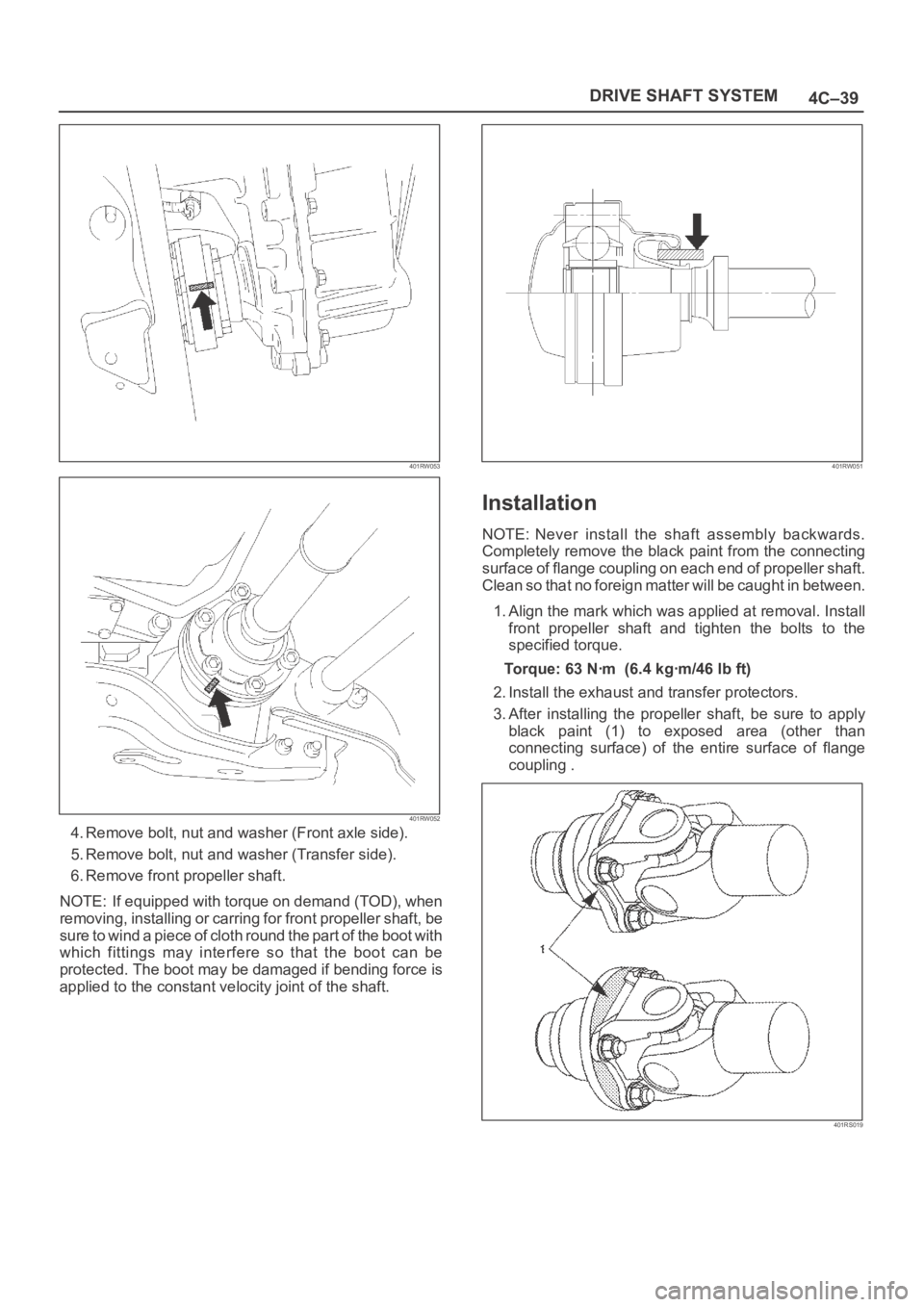
4. Remove bolt, nut and washer (Front axle side).
5. Remove bolt, nut and washer (Transfer side).
6. Remove front propeller shaft.
NOTE: If equipped with torque on demand (TOD), when
removing, installing or carring for front propeller shaft, be
sure to wind a piece of cloth round the part of the boot with
which fittings may interfere so that the boot can be
protected. The boot may be damaged if bending force is
applied to the constant velocity joint of the shaft.
401RW051
Installation
NOTE: Never install the shaft assembly backwards.
Completely remove the black paint from the connecting
surface of flange coupling on each end of propeller shaft.
Clean so that no foreign matter will be caught in between.
1. Align the mark which was applied at removal. Install
front propeller shaft and tighten the bolts to the
specified torque.
Torque:63Nꞏm (6.4kgꞏm/46lbft)
2. Install the exhaust and transfer protectors.
3. After installing the propeller shaft, be sure to apply
black paint (1) to exposed area (other than
connecting surface) of the entire surface of flange
coupling .
401RS019
Page 709 of 6000
4C–43 DRIVE SHAFT SYSTEM
Play in Universal Joint
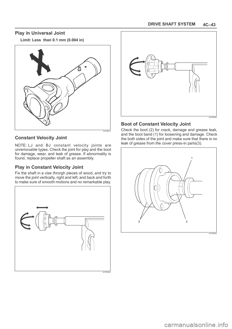
Limit: Less than 0.1 mm (0.004 in)
401RS010
Constant Velocity Joint
NOTE: LJ and BJ constant velocity joints are
unremovable types. Check the joint for play and the boot
for damage, wear, and leak of grease. If abnormality is
found, replace propeller shaft as an assembly.
Play in Constant Velocity Joint
Fix the shaft in a vise throrgh pieces of wood, and try to
move the joint vertically, right and left, and back and forth
to make sure of smooth motions and no remarkable play.
401RW050
401RW049
Boot of Constant Velocity Joint
Check the boot (2) for crack, damage and grease leak,
and the boot band (1) for loosening and damage. Check
the both sides of the joint and make sure that there is no
leak of grease from the cover press-in parts(3).
401RW048
Page 1441 of 6000
6E–324
ENGINE DRIVEABILITY AND EMISSIONS
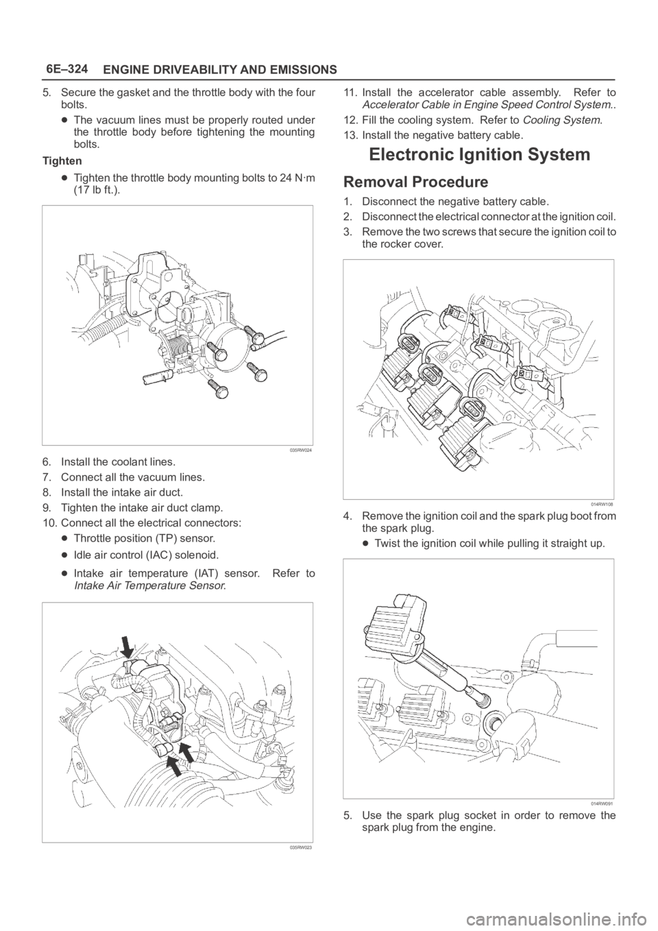
5. Secure the gasket and the throttle body with the four
bolts.
The vacuum lines must be properly routed under
the throttle body before tightening the mounting
bolts.
Tighten
Tighten the throttle body mounting bolts to 24 Nꞏm
(17 lb ft.).
035RW024
6. Install the coolant lines.
7. Connect all the vacuum lines.
8. Install the intake air duct.
9. Tighten the intake air duct clamp.
10. Connect all the electrical connectors:
Throttle position (TP) sensor.
Idle air control (IAC) solenoid.
Intake air temperature (IAT) sensor. Refer to
Intake Air Temperature Sensor.
035RW023
11. Install the accelerator cable assembly. Refer to
Accelerator Cable in Engine Speed Control System..
12. Fill the cooling system. Refer to
Cooling System.
13. Install the negative battery cable.
Electronic Ignition System
Removal Procedure
1. Disconnect the negative battery cable.
2. Disconnect the electrical connector at the ignition coil.
3. Remove the two screws that secure the ignition coil to
the rocker cover.
014RW108
4. Remove the ignition coil and the spark plug boot from
the spark plug.
Twist the ignition coil while pulling it straight up.
014RW091
5. Use the spark plug socket in order to remove the
spark plug from the engine.
Page 1442 of 6000
6E–325 ENGINE DRIVEABILITY AND EMISSIONS
Spark Plug Gap Check
Check the gap of all spark plugs before installation.
Use a round wire feeler gauge to ensure an accurate
check.
Plugs installed with the wrong gap can cause poor
engine performance and excessive emissions.
Installation Procedure
NOTE: The plug must thread smoothly into the cylinder
head and be fully seated. Use a thread chaser if
necessary to clean the threads in the cylinder head.
Cross-threading or failure to fully seat the spark plug can
cause plug overheating, exhaust blow-by gas, or thread
damage. Do not overtighten the spark plugs. Over
tightening can cause aluminum threads to strip.
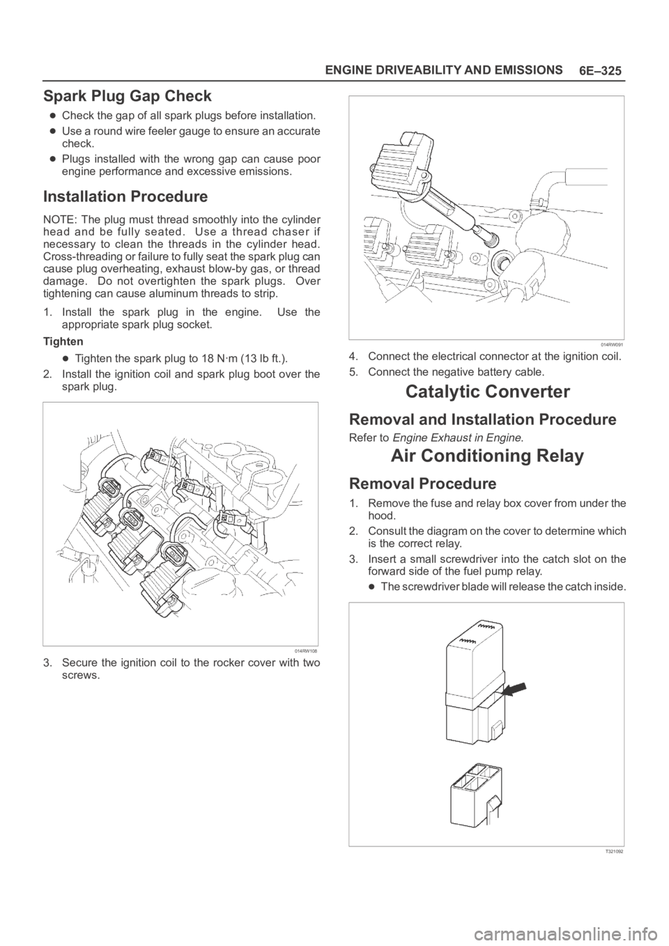
1. Install the spark plug in the engine. Use the
appropriate spark plug socket.
Tighten
Tighten the spark plug to 18 Nꞏm (13 lb ft.).
2. Install the ignition coil and spark plug boot over the
spark plug.
014RW108
3. Secure the ignition coil to the rocker cover with two
screws.
014RW091
4. Connect the electrical connector at the ignition coil.
5. Connect the negative battery cable.
Catalytic Converter
Removal and Installation Procedure
Refer to Engine Exhaust in Engine.
Air Conditioning Relay
Removal Procedure
1. Remove the fuse and relay box cover from under the
hood.
2. Consult the diagram on the cover to determine which
is the correct relay.
3. Insert a small screwdriver into the catch slot on the
forward side of the fuel pump relay.
The screwdriver blade will release the catch inside.
T321092
Page 1462 of 6000
6E–345 ENGINE DRIVEABILITY AND EMISSIONS
0014
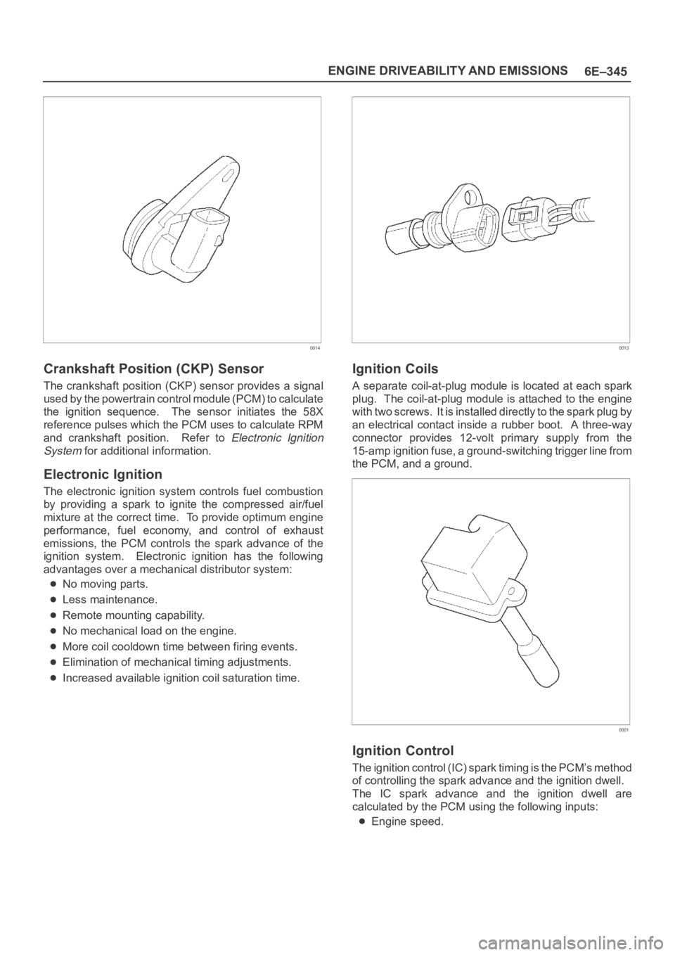
Crankshaft Position (CKP) Sensor
The crankshaft position (CKP) sensor provides a signal
used by the powertrain control module (PCM) to calculate
the ignition sequence. The sensor initiates the 58X
reference pulses which the PCM uses to calculate RPM
and crankshaft position. Refer to
Electronic Ignition
System
for additional information.
Electronic Ignition
The electronic ignition system controls fuel combustion
by providing a spark to ignite the compressed air/fuel
mixture at the correct time. To provide optimum engine
performance, fuel economy, and control of exhaust
emissions, the PCM controls the spark advance of the
ignition system. Electronic ignition has the following
advantages over a mechanical distributor system:
No moving parts.
Less maintenance.
Remote mounting capability.
No mechanical load on the engine.
More coil cooldown time between firing events.
Elimination of mechanical timing adjustments.
Increased available ignition coil saturation time.
0013
Ignition Coils
A separate coil-at-plug module is located at each spark
plug. The coil-at-plug module is attached to the engine
with two screws. It is installed directly to the spark plug by
an electrical contact inside a rubber boot. A three-way
connector provides 12-volt primary supply from the
15-amp ignition fuse, a ground-switching trigger line from
the PCM, and a ground.
0001
Ignition Control
The ignition control (IC) spark timing is the PCM’s method
of controlling the spark advance and the ignition dwell.
The IC spark advance and the ignition dwell are
calculated by the PCM using the following inputs:
Engine speed.
Page 2533 of 6000
7C–24CLUTCH
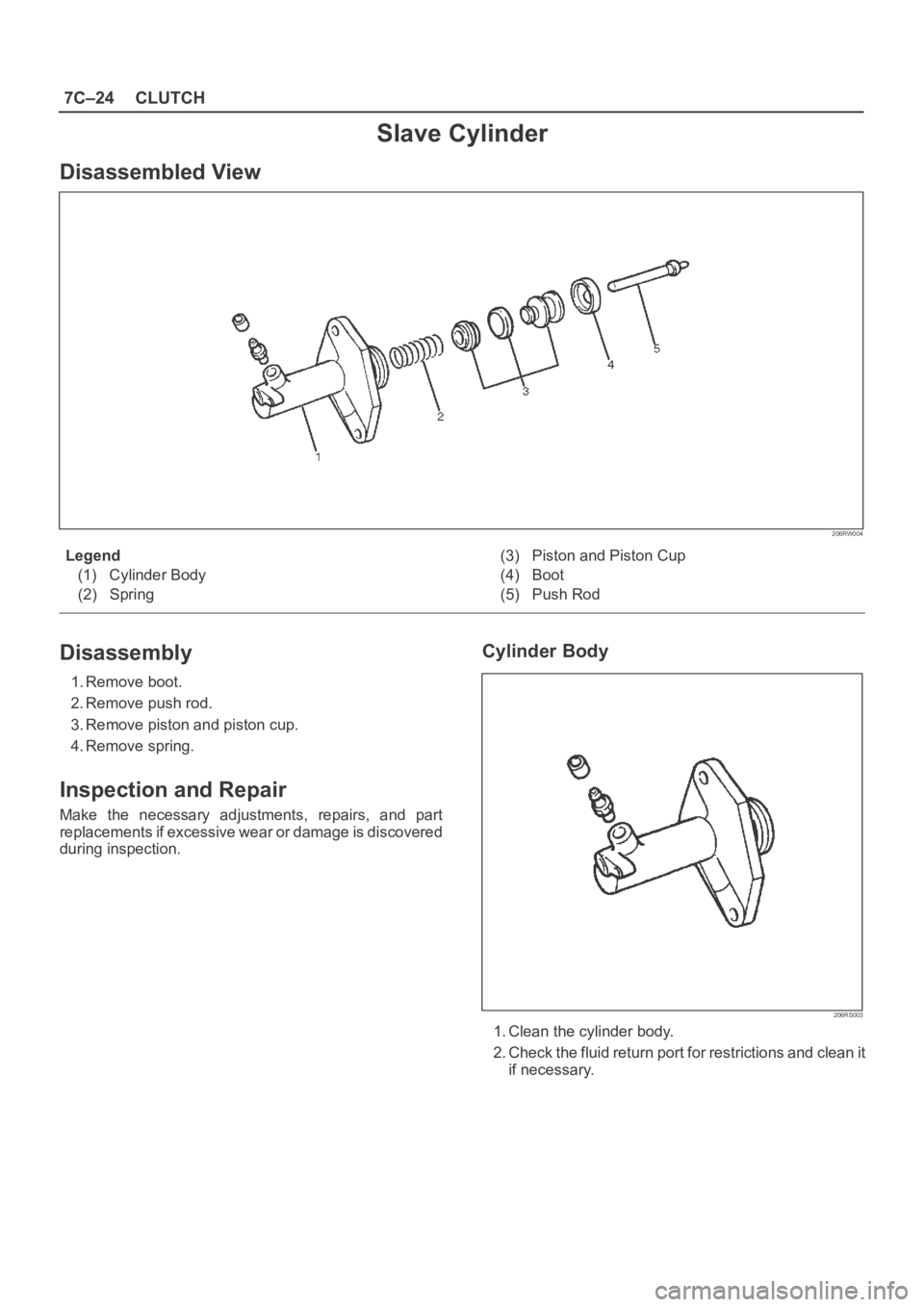
Slave Cylinder
Disassembled View
206RW004
Legend
(1) Cylinder Body
(2) Spring(3) Piston and Piston Cup
(4) Boot
(5) Push Rod
Disassembly
1. Remove boot.
2. Remove push rod.
3. Remove piston and piston cup.
4. Remove spring.
Inspection and Repair
Make the necessary adjustments, repairs, and part
replacements if excessive wear or damage is discovered
during inspection.
Cylinder Body
206RS003
1. Clean the cylinder body.
2. Check the fluid return port for restrictions and clean it
if necessary.
Page 4245 of 6000
4C–39 DRIVE SHAFT SYSTEM
401RW053
401RW052
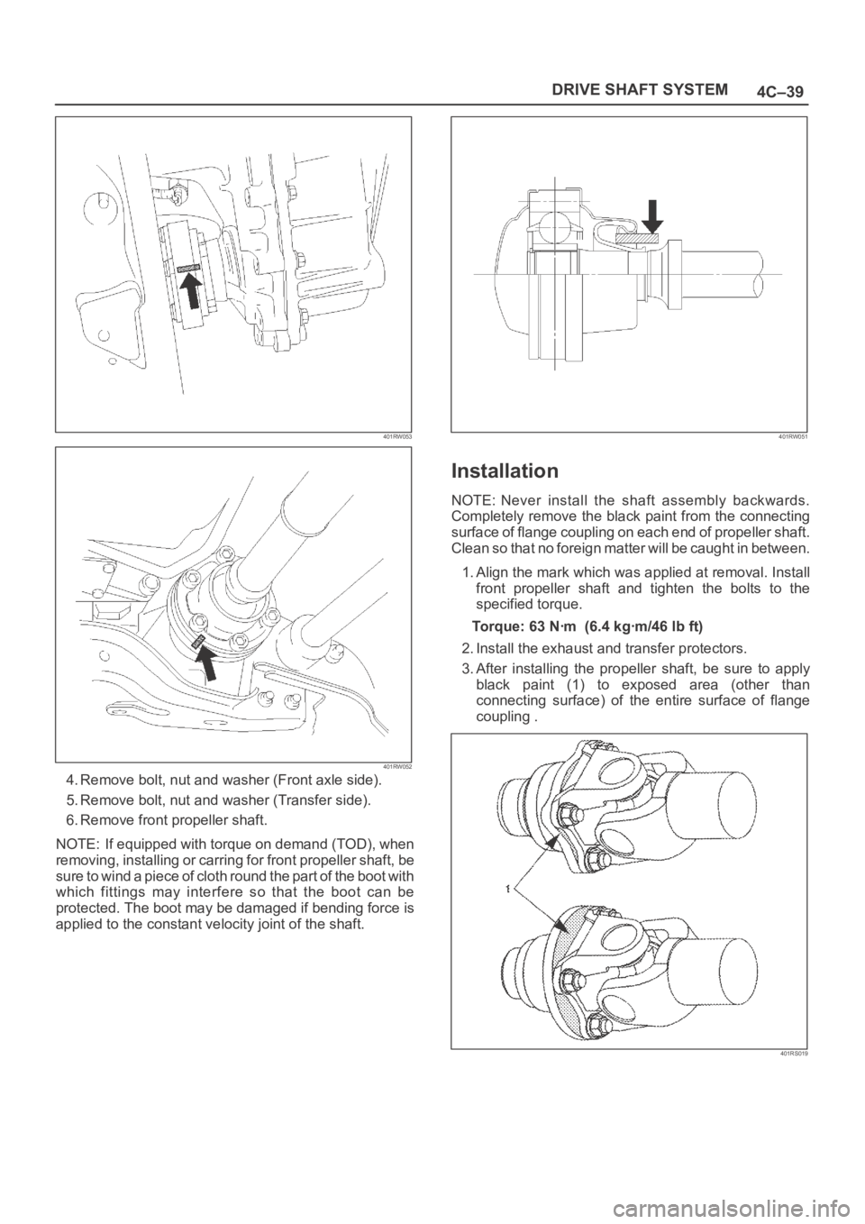
4. Remove bolt, nut and washer (Front axle side).
5. Remove bolt, nut and washer (Transfer side).
6. Remove front propeller shaft.
NOTE: If equipped with torque on demand (TOD), when
removing, installing or carring for front propeller shaft, be
sure to wind a piece of cloth round the part of the boot with
which fittings may interfere so that the boot can be
protected. The boot may be damaged if bending force is
applied to the constant velocity joint of the shaft.
401RW051
Installation
NOTE: Never install the shaft assembly backwards.
Completely remove the black paint from the connecting
surface of flange coupling on each end of propeller shaft.
Clean so that no foreign matter will be caught in between.
1. Align the mark which was applied at removal. Install
front propeller shaft and tighten the bolts to the
specified torque.
Torque:63Nꞏm (6.4kgꞏm/46lbft)
2. Install the exhaust and transfer protectors.
3. After installing the propeller shaft, be sure to apply
black paint (1) to exposed area (other than
connecting surface) of the entire surface of flange
coupling .
401RS019
Page 4249 of 6000
4C–43 DRIVE SHAFT SYSTEM
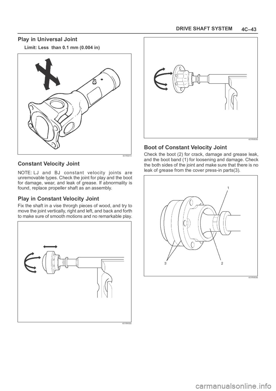
Play in Universal Joint
Limit: Less than 0.1 mm (0.004 in)
401RS010
Constant Velocity Joint
NOTE: LJ and BJ constant velocity joints are
unremovable types. Check the joint for play and the boot
for damage, wear, and leak of grease. If abnormality is
found, replace propeller shaft as an assembly.
Play in Constant Velocity Joint
Fix the shaft in a vise throrgh pieces of wood, and try to
move the joint vertically, right and left, and back and forth
to make sure of smooth motions and no remarkable play.
401RW050
401RW049
Boot of Constant Velocity Joint
Check the boot (2) for crack, damage and grease leak,
and the boot band (1) for loosening and damage. Check
the both sides of the joint and make sure that there is no
leak of grease from the cover press-in parts(3).
401RW048
Page 4981 of 6000
6E–324
ENGINE DRIVEABILITY AND EMISSIONS
5. Secure the gasket and the throttle body with the four
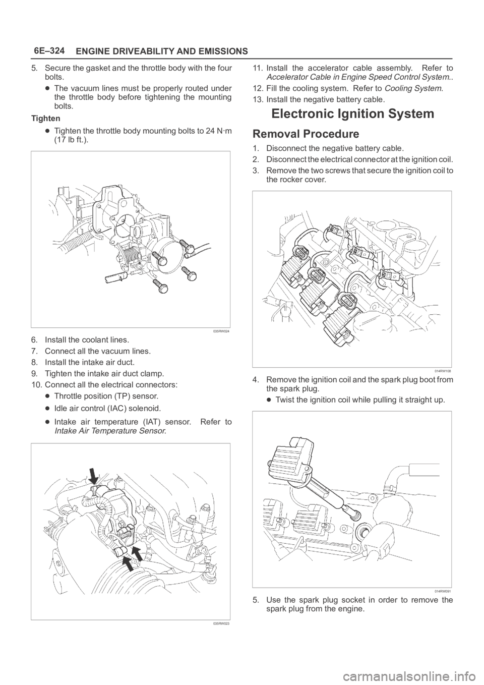
bolts.
The vacuum lines must be properly routed under
the throttle body before tightening the mounting
bolts.
Tighten
Tighten the throttle body mounting bolts to 24 Nꞏm
(17 lb ft.).
035RW024
6. Install the coolant lines.
7. Connect all the vacuum lines.
8. Install the intake air duct.
9. Tighten the intake air duct clamp.
10. Connect all the electrical connectors:
Throttle position (TP) sensor.
Idle air control (IAC) solenoid.
Intake air temperature (IAT) sensor. Refer to
Intake Air Temperature Sensor.
035RW023
11. Install the accelerator cable assembly. Refer to
Accelerator Cable in Engine Speed Control System..
12. Fill the cooling system. Refer to
Cooling System.
13. Install the negative battery cable.
Electronic Ignition System
Removal Procedure
1. Disconnect the negative battery cable.
2. Disconnect the electrical connector at the ignition coil.
3. Remove the two screws that secure the ignition coil to
the rocker cover.
014RW108
4. Remove the ignition coil and the spark plug boot from
the spark plug.
Twist the ignition coil while pulling it straight up.
014RW091
5. Use the spark plug socket in order to remove the
spark plug from the engine.
Page 4982 of 6000
6E–325 ENGINE DRIVEABILITY AND EMISSIONS
Spark Plug Gap Check
Check the gap of all spark plugs before installation.
Use a round wire feeler gauge to ensure an accurate
check.
Plugs installed with the wrong gap can cause poor
engine performance and excessive emissions.
Installation Procedure
NOTE: The plug must thread smoothly into the cylinder
head and be fully seated. Use a thread chaser if
necessary to clean the threads in the cylinder head.
Cross-threading or failure to fully seat the spark plug can
cause plug overheating, exhaust blow-by gas, or thread
damage. Do not overtighten the spark plugs. Over
tightening can cause aluminum threads to strip.
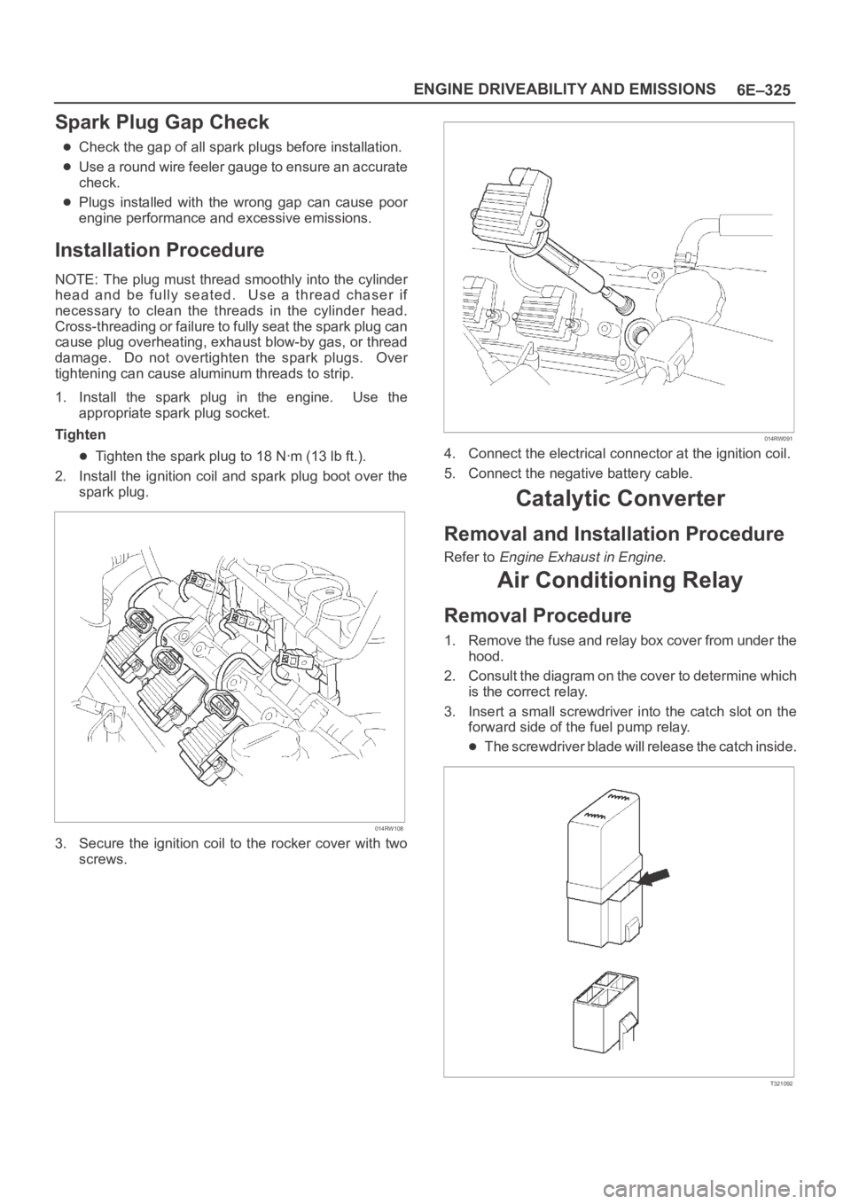
1. Install the spark plug in the engine. Use the
appropriate spark plug socket.
Tighten
Tighten the spark plug to 18 Nꞏm (13 lb ft.).
2. Install the ignition coil and spark plug boot over the
spark plug.
014RW108
3. Secure the ignition coil to the rocker cover with two
screws.
014RW091
4. Connect the electrical connector at the ignition coil.
5. Connect the negative battery cable.
Catalytic Converter
Removal and Installation Procedure
Refer to Engine Exhaust in Engine.
Air Conditioning Relay
Removal Procedure
1. Remove the fuse and relay box cover from under the
hood.
2. Consult the diagram on the cover to determine which
is the correct relay.
3. Insert a small screwdriver into the catch slot on the
forward side of the fuel pump relay.
The screwdriver blade will release the catch inside.
T321092