change wheel OPEL FRONTERA 1998 Workshop Manual
[x] Cancel search | Manufacturer: OPEL, Model Year: 1998, Model line: FRONTERA, Model: OPEL FRONTERA 1998Pages: 6000, PDF Size: 97 MB
Page 470 of 6000
DIFFERENTIAL (REAR 220mm)
4A2A–3
Diagnosis
Many noises that seem to come from the rear axle
actually originate from other sources such as tires, road
surface, wheel bearings, engine, transmission, muffler, or
body drumming. Investigate to find the source of the
noise before disassembling the rear axle. Rear axles, like
any other mechanical device, are not absolutely quiet but
should be considered quiet unless some abnormal noise
is present.
To make a systematic check for axle noise, observe the
following:
1. Select a level asphalt road to reduce tire noise and
body drumming.
2. Check rear axle lubricant level to assure correct level,
and then drive the vehicle far enough to thoroughly
warm up the rear axle lubricant.
3. Note the speed at which noise occurs. Stop the
vehicle and put the transmission in neutral. Run the
engine speed slowly up and down to determine if the
noise is caused by exhaust, muffler noise, or other
engine conditions.
4. Tire noise changes with different road surfaces; axle
noises do not. Temporarily inflate all tires to 344 kPa
(3.5kg/cm
2, 50 psi) (for test purposes only). This will
change noise caused by tires but will not affect noise
caused by the rear axle.
Rear axle noise usually stops when coasting at
speeds under 48 km/h (30 mph); however, tire noise
continues with a lower tone. Rear axle noise usually
changes when comparing pull and coast, but tire
noise stays about the same.
Distinguish between tire noise and rear axle noise by
noting if the noise changes with various speeds or
sudden acceleration and deceleration. Exhaust and
axle noise vary under these conditions, while tire
noise remains constant and is more pronounced at
speeds of 32 to 48 km/h (20 to 30 mph). Further check
for tire noise by driving the vehicle over smooth
pavements or dirt roads (not gravel) with the tires at
normal pressure. If the noise is caused by tires, it will
change noticeably with changes in road surface.
5. Loose or rough front wheel bearings will cause noise
which may be confused with rear axle noise; however,
front wheel bearing noise does not change when
comparing drive and coast. Light application of the
brake while holding vehicle speed steady will often
cause wheel bearing noise to diminish. Front wheel
bearings may be checked for noise by jacking up the
wheels and spinning them or by shaking the wheels to
determine if bearings are loose.
6. Rear suspension rubber bushings and spring
insulators dampen out rear axle noise when correctly
installed. Check to see that there is no link or rod
loosened or metal–to–metal contact.
7. Make sure that there is no metal–to–metal contact
between the floor and the frame.
After the noise has been determined to be in the axle, the
type of axle noise should be determined, in order to make
any necessary repairs.
Gear Noise
Gear noise (whine) is audible from 32 to 89 km/h (20 to 55
mph) under four driving conditions.
1. Driving under acceleration or heavy pull.
2. Driving under load or under constant speed.
3. When using enough throttle to keep the vehicle from
driving the engine while the vehicle slows down
gradually (engine still pulls slightly).
4. When coasting with the vehicle in gear and the throttle
closed. The gear noise is usually more noticeable
between 48 and 64 km/h (30 and 40 mph) and 80 and
89 km/h (50 and 55 mph).
Bearing Noise
Bad bearings generally produce a rough growl or grating
sound, rather than the whine typical of gear noise.
Bearing noise frequently “wow–wows” at bearing rpm,
indicating a bad pinion or rear axle side bearing. This
noise can be confused with rear wheel bearing noise.
Rear Wheel Bearing Noise
Rear wheel bearing noise continues to be heard while
coasting at low speed with transmission in neutral. Noise
may diminish by gentle braking. Jack up the rear wheels,
spin them by hand and listen for noise at the hubs.
Replace any faulty wheel bearings.
Knock At Low Speeds
Low speed knock can be caused by worn universal joints
or a side gear hub counter bore in the cage that is worn
oversize. Inspect and replace universal joints or cage and
side gears as required.
Backlash Clunk
Excessive clunk on acceleration and deceleration can be
caused by a worn rear axle pinion shaft, a worn cage,
excessive clearance between the axle and the side gear
splines, excessive clearance between the side gear hub
and the counterbore in the cage, worn pinion and side
gear teeth, worn thrust washers, or excessive drive pinion
and ring gear backlash. Remove worn parts and replace
as required. Select close–fitting parts when possible.
Adjust pinion and ring gear backlash.
Page 506 of 6000
DIFFERENTIAL (REAR 244mm)
4A2B–3
Diagnosis
Many noises that seem to come from the rear axle
actually originate from other sources such as tires, road
surface, wheel bearings, engine, transmission, muffler, or
body drumming. Investigate to find the source of the
noise before disassembling the rear axle. Rear axles, like
any other mechanical device, are not absolutely quiet but
should be considered quiet unless some abnormal noise
is present.
To make a systematic check for axle noise, observe the
following:
1. Select a level asphalt road to reduce tire noise and
body drumming.
2. Check rear axle lubricant level to assure correct level,
and then drive the vehicle far enough to thoroughly
warm up the rear axle lubricant.
3. Note the speed at which noise occurs. Stop the
vehicle and put the transmission in neutral. Run the
engine speed slowly up and down to determine if the
noise is caused by exhaust, muffler noise, or other
engine conditions.
4. Tire noise changes with different road surfaces; axle
noises do not. Temporarily inflate all tires to 344 kPa
(3.5kg/cm
2, 50 psi) (for test purposes only). This will
change noise caused by tires but will not affect noise
caused by the rear axle.
Rear axle noise usually stops when coasting at
speeds under 48 km/h (30 mph); however, tire noise
continues with a lower tone. Rear axle noise usually
changes when comparing pull and coast, but tire
noise stays about the same.
Distinguish between tire noise and rear axle noise by
noting if the noise changes with various speeds or
sudden acceleration and deceleration. Exhaust and
axle noise vary under these conditions, while tire
noise remains constant and is more pronounced at
speeds of 32 to 48 km/h (20 to 30 mph). Further check
for tire noise by driving the vehicle over smooth
pavements or dirt roads (not gravel) with the tires at
normal pressure. If the noise is caused by tires, it will
change noticeably with changes in road surface.
5. Loose or rough front wheel bearings will cause noise
which may be confused with rear axle noise; however,
front wheel bearing noise does not change when
comparing drive and coast. Light application of the
brake while holding vehicle speed steady will often
cause wheel bearing noise to diminish. Front wheel
bearings may be checked for noise by jacking up the
wheels and spinning them or by shaking the wheels to
determine if bearings are loose.
6. Rear suspension rubber bushings and spring
insulators dampen out rear axle noise when correctly
installed. Check to see that there is no link or rod
loosened or metal–to–metal contact.
7. Make sure that there is no metal–to–metal contact
between the floor and the frame.
After the noise has been determined to be in the axle, the
type of axle noise should be determined, in order to make
any necessary repairs.
Gear Noise
Gear noise (whine) is audible from 32 to 89 km/h (20 to 55
mph) under four driving conditions.
1. Driving under acceleration or heavy pull.
2. Driving under load or under constant speed.
3. When using enough throttle to keep the vehicle from
driving the engine while the vehicle slows down
gradually (engine still pulls slightly).
4. When coasting with the vehicle in gear and the throttle
closed. The gear noise is usually more noticeable
between 48 and 64 km/h (30 and 40 mph) and 80 and
89 km/h (50 and 55 mph).
Bearing Noise
Bad bearings generally produce a rough growl or grating
sound, rather than the whine typical of gear noise.
Bearing noise frequently “wow–wows” at bearing rpm,
indicating a bad pinion or rear axle side bearing. This
noise can be confused with rear wheel bearing noise.
Rear Wheel Bearing Noise
Rear wheel bearing noise continues to be heard while
coasting at low speed with transmission in neutral. Noise
may diminish by gentle braking. Jack up the rear wheels,
spin them by hand and listen for noise at the hubs.
Replace any faulty wheel bearings.
Knock At Low Speeds
Low speed knock can be caused by worn universal joints
or a side gear hub counter bore in the cage that is worn
oversize. Inspect and replace universal joints or cage and
side gears as required.
Backlash Clunk
Excessive clunk on acceleration and deceleration can be
caused by a worn rear axle pinion shaft, a worn cage,
excessive clearance between the axle and the side gear
splines, excessive clearance between the side gear hub
and the counterbore in the cage, worn pinion and side
gear teeth, worn thrust washers, or excessive drive pinion
and ring gear backlash. Remove worn parts and replace
as required. Select close–fitting parts when possible.
Adjust pinion and ring gear backlash.
Page 541 of 6000
4B1–8
DRIVE LINE CONTROL SYSTEM (SHIFT ON THE FLY)
Normal Operation
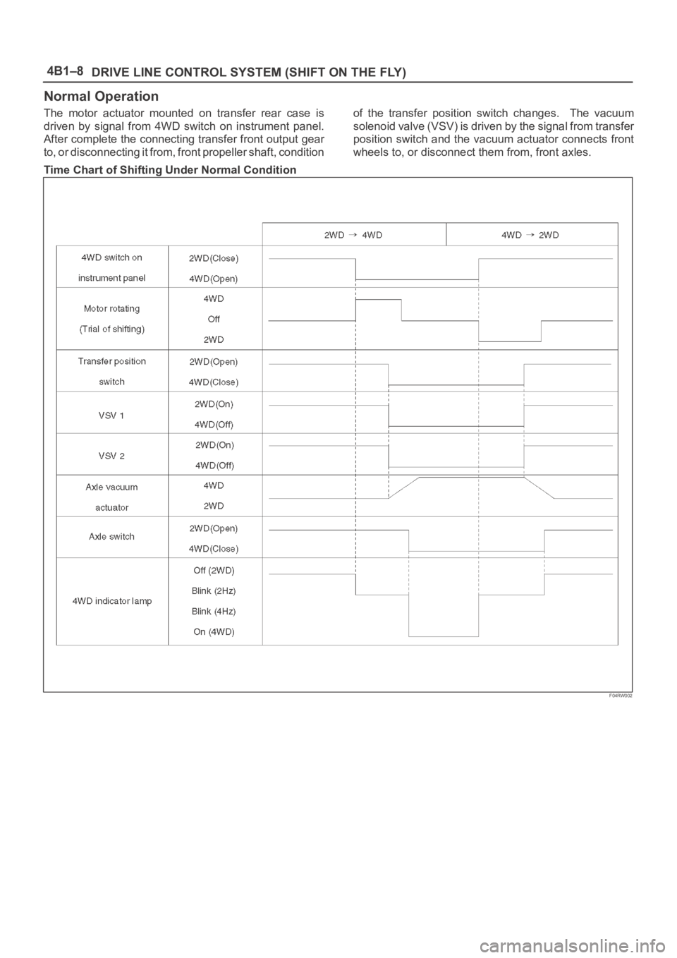
The motor actuator mounted on transfer rear case is
driven by signal from 4WD switch on instrument panel.
After complete the connecting transfer front output gear
to, or disconnecting it from, front propeller shaft, conditionof the transfer position switch changes. The vacuum
solenoid valve (VSV) is driven by the signal from transfer
position switch and the vacuum actuator connects front
wheels to, or disconnect them from, front axles.
Time Chart of Shifting Under Normal Condition
F04RW002
Page 544 of 6000
4B1–11 DRIVE LINE CONTROL SYSTEM (SHIFT ON THE FLY)
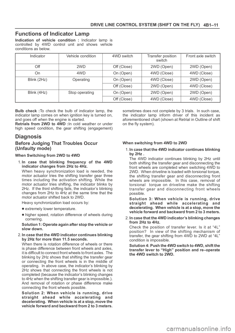
Functions of Indicator Lamp
Indication of vehicle condition : Indicator lamp is
controlled by 4WD control unit and shows vehicle
conditions as below.
Indicator
Vehicle condition4WD switchTransfer position
switchFront axle switch
Off2WDOff (Close)2WD (Open)2WD (Open)
On4WDOn (Open)4WD (Close)4WD (Close)
Blink (2Hz)OperatingOn (Open)4WD (Close)2WD (Open)
Off (Close)2WD (Open)4WD (Close)
Blink (4Hz)Stop operatingOn (Open)2WD (Open)2WD (Open)
Off (Close)4WD (Close)4WD (Close)
Bulb check :To check the bulb of indicator lamp, the
indicator lamp comes on when ignition key is turned on,
and goes off when the engine is started.
Retrials from 2WD to 4WD :In cold weather or under
high speed condition, the gear shifting (engagement)sometimes does not complete by 3 trials. In such case,
the indicator lamp inform driver of this incident as
aforementioned chart (shown at Retrial in Outline of shift
on the fly system).
Diagnosis
Before Judging That Troubles Occur
(Unfaulty mode)
When Switching from 2WD to 4WD
1.In case that blinking frequency of the 4WD
indicator changes from 2Hz to 4Hz.
When heavy synchronization load is needed, the
motor actuator tries the shifting transfer gear three
times including the activation shifting. While the
motor actuator tries shifting, the indicator blinks by
2Hz. If the third shifting fails, the indicator’s blinking
changes from 2Hz to 4Hz at the same time that the
motor actuator shifted back to 2WD.
Heavy synchronization load occurs by:
extremely lower temperature.
higher speed, rotation difference of wheels during
cornering.
Solution 1: Operate again after stop the vehicle or
slow down.
2.In case that the 4WD indicator continues blinking
by 2Hz for more than 11.5 seconds.
When there is rotation difference of wheels or there
is phase difference between front wheels and axles,
it is difficult to connect front wheels to front axles. The
blinking by 2Hz shows that shifting the transfer gear
or connecting the front wheels is in the middle of
operating. In above case, the indicator’s blinking by
2Hz shows that connecting the front wheels is not
completed (because the indicator’s blinking changes
to 4Hz when the shifting transfer gear is impossible.).
And removal of rotation or phase difference make
connecting the front wheels possible.
Solution 2: When vehicle is running, drive
straight ahead while accelerating and
decelerating. When vehicle is at a stop, move the
vehicle forward and backward from 2 to 3 meters.When switching from 4WD to 2WD
1.In case that the 4WD indicator continues blinking
by 2Hz .
The 4WD indicator continues blinking by 2Hz until
both shifting the transfer gear and disconnecting the
front wheels are completed when switching 4WD to
2WD. When driveline is loaded with torsional torque,
the shifting transfer gear and disconnecting front
wheels are impossible. In this case, removal of
torsional torque on driveline make the shifting
transfer gear and disconnecting front wheels
possible.
Solution 3: When vehicle is running, drive
straight ahead while accelerating and
decelerating. When vehicle is at a stop, move the
vehicle forward and backward from 2 to 3 meters.
2.In case that the 4WD indicator’s blinking changes
from 2Hz to 4Hz.
Check the position of transfer lever. Is it at “4L”
position? In view of the shifting mechanism of
transfer, the gear shifting from 4WD to 2WD at “4L”
condition is impossible.
Solution 4: Push the 4WD switch to 4WD, shift the
transfer lever to “High” position and re–operate
the 4WD switch to 2WD.
Page 573 of 6000
DRIVE LINE CONTROL SYSTEM (TOD) 4B2–2
General Description
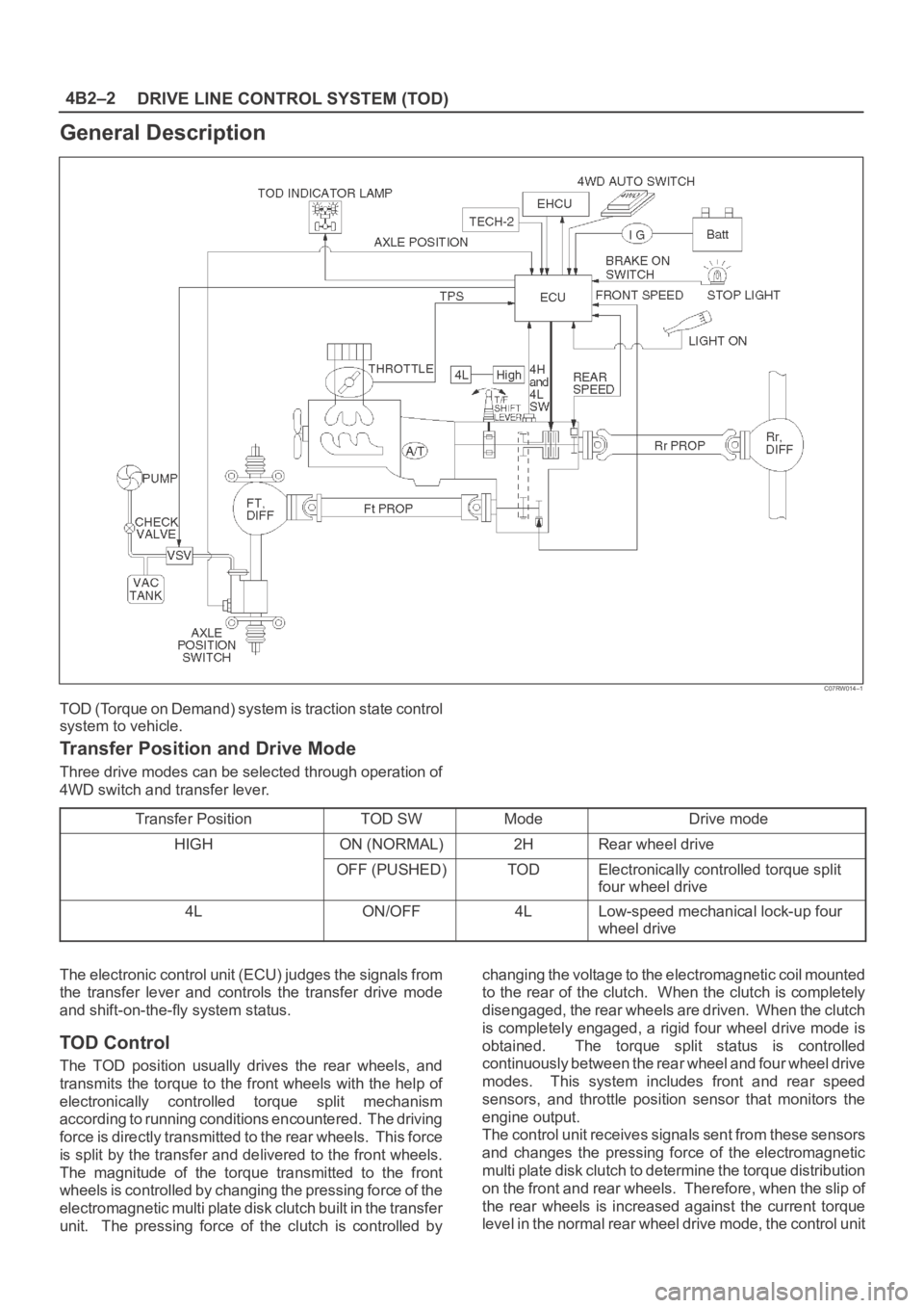
C07RW014–1
TOD (Torque on Demand) system is traction state control
system to vehicle.
Transfer Position and Drive Mode
Three drive modes can be selected through operation of
4WD switch and transfer lever.
Transfer Position
TOD SWModeDrive mode
HIGHON (NORMAL)2HRear wheel drive
OFF (PUSHED)TODElectronically controlled torque split
four wheel drive
4LON/OFF4LLow-speed mechanical lock-up four
wheel drive
The electronic control unit (ECU) judges the signals from
the transfer lever and controls the transfer drive mode
and shift-on-the-fly system status.
TOD Control
The TOD position usually drives the rear wheels, and
transmits the torque to the front wheels with the help of
electronically controlled torque split mechanism
according to running conditions encountered. The driving
force is directly transmitted to the rear wheels. This force
is split by the transfer and delivered to the front wheels.
The magnitude of the torque transmitted to the front
wheels is controlled by changing the pressing force of the
electromagnetic multi plate disk clutch built in the transfer
unit. The pressing force of the clutch is controlled bychanging the voltage to the electromagnetic coil mounted
to the rear of the clutch. When the clutch is completely
disengaged, the rear wheels are driven. When the clutch
is completely engaged, a rigid four wheel drive mode is
obtained. The torque split status is controlled
continuously between the rear wheel and four wheel drive
modes. This system includes front and rear speed
sensors, and throttle position sensor that monitors the
engine output.
The control unit receives signals sent from these sensors
and changes the pressing force of the electromagnetic
multi plate disk clutch to determine the torque distribution
on the front and rear wheels. Therefore, when the slip of
the rear wheels is increased against the current torque
level in the normal rear wheel drive mode, the control unit
Page 606 of 6000
4B2–35 DRIVE LINE CONTROL SYSTEM (TOD)
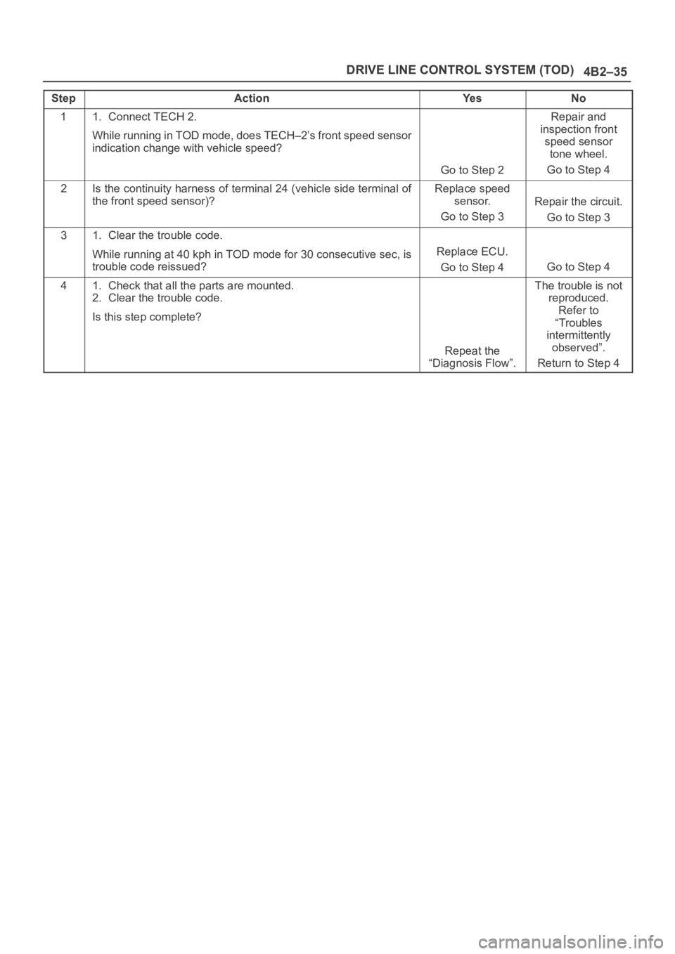
StepActionYe sNo
11. Connect TECH 2.
While running in TOD mode, does TECH–2’s front speed sensor
indication change with vehicle speed?
Go to Step 2
Repair and
inspection front
speed sensor
tone wheel.
Go to Step 4
2Is the continuity harness of terminal 24 (vehicle side terminal of
the front speed sensor)?Replace speed
sensor.
Go to Step 3
Repair the circuit.
Go to Step 3
31. Clear the trouble code.
While running at 40 kph in TOD mode for 30 consecutive sec, is
trouble code reissued?
Replace ECU.
Go to Step 4
Go to Step 4
41. Check that all the parts are mounted.
2. Clear the trouble code.
Is this step complete?
Repeat the
“Diagnosis Flow”.
The trouble is not
reproduced.
Refer to
“Troubles
intermittently
observed”.
Return to Step 4
Page 608 of 6000
4B2–37 DRIVE LINE CONTROL SYSTEM (TOD)
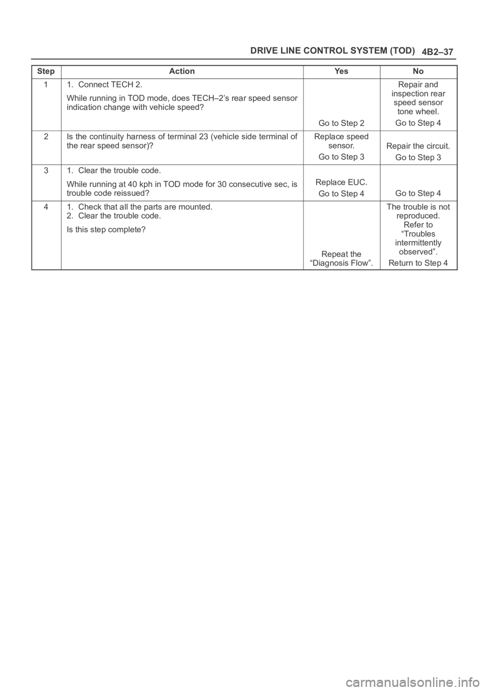
StepActionYe sNo
11. Connect TECH 2.
While running in TOD mode, does TECH–2’s rear speed sensor
indication change with vehicle speed?
Go to Step 2
Repair and
inspection rear
speed sensor
tone wheel.
Go to Step 4
2Is the continuity harness of terminal 23 (vehicle side terminal of
the rear speed sensor)?Replace speed
sensor.
Go to Step 3
Repair the circuit.
Go to Step 3
31. Clear the trouble code.
While running at 40 kph in TOD mode for 30 consecutive sec, is
trouble code reissued?
Replace EUC.
Go to Step 4
Go to Step 4
41. Check that all the parts are mounted.
2. Clear the trouble code.
Is this step complete?
Repeat the
“Diagnosis Flow”.
The trouble is not
reproduced.
Refer to
“Troubles
intermittently
observed”.
Return to Step 4
Page 814 of 6000
5A–4
BRAKE CONTROL SYSTEM
normal braking when a malfunction has occurred in the
ABS.
The EHCU has a self-diagnosing function which can
indicate faulty circuits during diagnosis.
The EHCU is mounted on the engine compartment front
right side. It consists of a Motor, Plunger Pump, Solenoid
Valves and Check Valve.
On the outside, the relay box containing a motor relay and
a valve relay is installed.
Solenoid Valves: Reduces or holds the caliper fluid
pressure for each front disc brake or both rear disc brakes
according to the signal sent from the EHCU.
Reservoir: Temporarily holds the brake fluid that returns
from the front and rear disc brake caliper so that pressure
of front disc brake caliper can be reduced smoothly.
Plunger Pump: Feeds the brake fluid held in the reservoir
to the master cylinder.
Motor: Drives the pump according to the signal from
EHCU.
Check Valve: Controls the brake fluid flow.
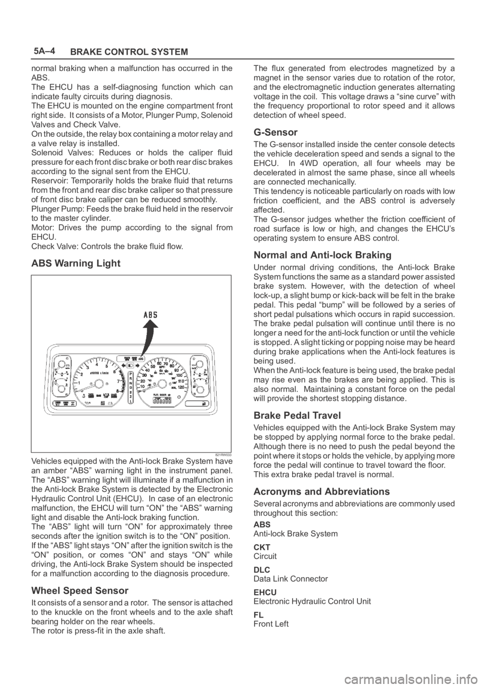
ABS Warning Light
821RW033Vehicles equipped with the Anti-lock Brake System have
an amber “ABS” warning light in the instrument panel.
The “ABS” warning light will illuminate if a malfunction in
the Anti-lock Brake System is detected by the Electronic
Hydraulic Control Unit (EHCU). In case of an electronic
malfunction, the EHCU will turn “ON” the “ABS” warning
light and disable the Anti-lock braking function.
The “ABS” light will turn “ON” for approximately three
seconds after the ignition switch is to the “ON” position.
If the “ABS” light stays “ON” after the ignition switch is the
“ON” position, or comes “ON” and stays “ON” while
driving, the Anti-lock Brake System should be inspected
for a malfunction according to the diagnosis procedure.
Wheel Speed Sensor
It consists of a sensor and a rotor. The sensor is attached
to the knuckle on the front wheels and to the axle shaft
bearing holder on the rear wheels.
The rotor is press-fit in the axle shaft.The flux generated from electrodes magnetized by a
magnet in the sensor varies due to rotation of the rotor,
and the electromagnetic induction generates alternating
voltage in the coil. This voltage draws a “sine curve” with
the frequency proportional to rotor speed and it allows
detection of wheel speed.
G-Sensor
The G-sensor installed inside the center console detects
the vehicle deceleration speed and sends a signal to the
EHCU. In 4WD operation, all four wheels may be
decelerated in almost the same phase, since all wheels
are connected mechanically.
This tendency is noticeable particularly on roads with low
friction coefficient, and the ABS control is adversely
affected.
The G-sensor judges whether the friction coefficient of
road surface is low or high, and changes the EHCU’s
operating system to ensure ABS control.
Normal and Anti-lock Braking
Under normal driving conditions, the Anti-lock Brake
System functions the same as a standard power assisted
brake system. However, with the detection of wheel
lock-up, a slight bump or kick-back will be felt in the brake
pedal. This pedal “bump” will be followed by a series of
short pedal pulsations which occurs in rapid succession.
The brake pedal pulsation will continue until there is no
longer a need for the anti-lock function or until the vehicle
is stopped. A slight ticking or popping noise may be heard
during brake applications when the Anti-lock features is
being used.
When the Anti-lock feature is being used, the brake pedal
may rise even as the brakes are being applied. This is
also normal. Maintaining a constant force on the pedal
will provide the shortest stopping distance.
Brake Pedal Travel
Vehicles equipped with the Anti-lock Brake System may
be stopped by applying normal force to the brake pedal.
Although there is no need to push the pedal beyond the
point where it stops or holds the vehicle, by applying more
force the pedal will continue to travel toward the floor.
This extra brake pedal travel is normal.
Acronyms and Abbreviations
Several acronyms and abbreviations are commonly used
throughout this section:
ABS
Anti-lock Brake System
CKT
Circuit
DLC
Data Link Connector
EHCU
Electronic Hydraulic Control Unit
FL
Front Left
Page 821 of 6000
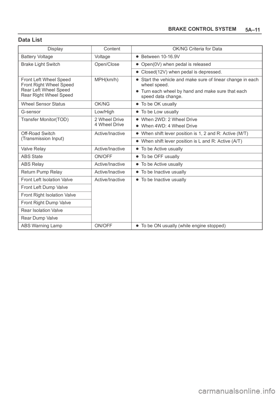
5A–11 BRAKE CONTROL SYSTEM
Data List
DisplayContentOK/NG Criteria for Data
Battery VoltageVo l t a g eBetween 10-16.9V
Brake Light SwitchOpen/CloseOpen(0V) when pedal is released
Closed(12V) when pedal is depressed.
Front Left Wheel Speed
Front Right Wheel Speed
Rear Left Wheel Speed
Rear Right Wheel SpeedMPH(km/h)Start the vehicle and make sure of linear change in each
wheel speed.
Turn each wheel by hand and make sure that each
speed data change.
Wheel Sensor StatusOK/NGTo be OK usually
G-sensorLow/HighTo be Low usually
Transfer Monitor(TOD)2 Wheel Drive
4 Wheel DriveWhen 2WD: 2 Wheel Drive
When 4WD: 4 Wheel Drive
Off-Road Switch
(Transmission Input)
Active/InactiveWhen shift lever position is 1, 2 and R: Active (M/T)
(Transmission Input)When shift lever position is L and R: Active (A/T)
Valve RelayActive/InactiveTo be Active usually
ABS StateON/OFFTo be OFF usually
ABS RelayActive/InactiveTo be Active usually
Return Pump RelayActive/InactiveTo be Inactive usually
Front Left Isolation ValveActive/InactiveTo be Inactive usually
Front Left Dump Valve
Front Right Isolation Valve
Front Right Dump Valve
Rear Isolation Valve
Rear Dump Valve
ABS Warning LampON/OFFTo be ON usually (while engine stopped)
Page 866 of 6000
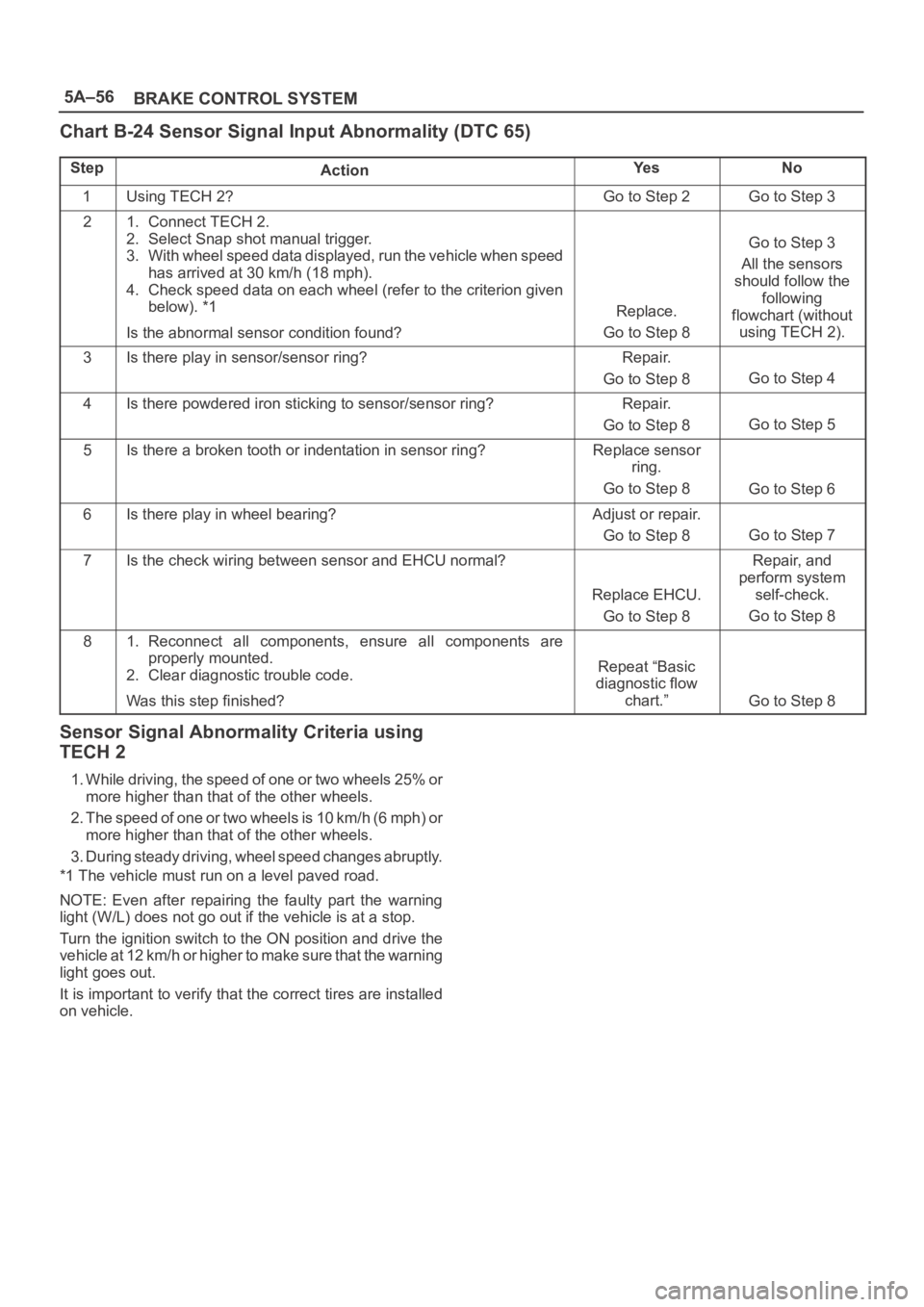
5A–56
BRAKE CONTROL SYSTEM
Chart B-24 Sensor Signal Input Abnormality (DTC 65)
StepActionYe sNo
1Using TECH 2?Go to Step 2Go to Step 3
21. Connect TECH 2.
2. Select Snap shot manual trigger.
3. With wheel speed data displayed, run the vehicle when speed
has arrived at 30 km/h (18 mph).
4. Check speed data on each wheel (refer to the criterion given
below). *1
Is the abnormal sensor condition found?
Replace.
Go to Step 8
Go to Step 3
All the sensors
should follow the
following
flowchart (without
using TECH 2).
3Is there play in sensor/sensor ring?Repair.
Go to Step 8
Go to Step 4
4Is there powdered iron sticking to sensor/sensor ring?Repair.
Go to Step 8
Go to Step 5
5Is there a broken tooth or indentation in sensor ring?Replace sensor
ring.
Go to Step 8
Go to Step 6
6Is there play in wheel bearing?Adjust or repair.
Go to Step 8
Go to Step 7
7Is the check wiring between sensor and EHCU normal?
Replace EHCU.
Go to Step 8
Repair, and
perform system
self-check.
Go to Step 8
81. Reconnect all components, ensure all components are
properly mounted.
2. Clear diagnostic trouble code.
Was this step finished?
Repeat “Basic
diagnostic flow
chart.”
Go to Step 8
Sensor Signal Abnormality Criteria using
TECH 2
1. While driving, the speed of one or two wheels 25% or
more higher than that of the other wheels.
2. The speed of one or two wheels is 10 km/h (6 mph) or
more higher than that of the other wheels.
3. During steady driving, wheel speed changes abruptly.
*1 The vehicle must run on a level paved road.
NOTE: Even after repairing the faulty part the warning
light (W/L) does not go out if the vehicle is at a stop.
Turn the ignition switch to the ON position and drive the
vehicle at 12 km/h or higher to make sure that the warning
light goes out.
It is important to verify that the correct tires are installed
on vehicle.