engine OPEL FRONTERA 1998 Workshop Manual
[x] Cancel search | Manufacturer: OPEL, Model Year: 1998, Model line: FRONTERA, Model: OPEL FRONTERA 1998Pages: 6000, PDF Size: 97 MB
Page 9 of 6000
PAGE BACK PAGE NEXT
THIS MALUAL INCLUDES THE FOLLOWING SECTIONS:
6VD1 / 6VE1
SECTION No. CONTRNTS
6A ENGINE MECHANICAL
6B ENGINE COOLING
6C ENGINE FUEL
6D1 ENGINE ELECTRICAL
6D2 IGNITION SYSTEM
6D3 STARTING AND CHARGING SYSTEM
6E ENGINE DRIVEABILITY AND EMISSIONS
6F ENGINE EXHAUST
6G ENGINE LUBRICATION
6H ENGINE SPEED CONTROL SYSTEM
6J INDUCTION
HOME
6A
6B
6C
6D1
6D2
6D3
6E
6F
6G
6H
6J
Page 10 of 6000
PAGE BACK PAGE NEXT
4JG2
4JX1 SECTION No. CONTRNTS
00 SERVICE INFORMATION
6A ENGINE MECHANICAL
6A2 4JG2-NA / 4JG2-TURBO ENGINE
6B ENGINE COOLING
6C FUEL SYSTEM
6D ENGINE ELECTRICAL
6E -
6F EXHAUST
6G -
SECTION No. CONTRNTS
6A ENGINE MECHANICAL
6B ENGINE COOLING
6C ENGINE FUEL
6D ENGINE ELECTRICAL
6E ENGINE DRIVEABILITY AND EMISSIONS
6F ENGINE EXHAUST
6G ENGINE LUBRICATION
6H ENGINE SPEED CONTROL
6J INDUCTION
HOME
00
6A
6A2
6B
6C
6D
6E
6F
6G
6A
6B
6C
6D
6E
6F
6G
6H
6J
Page 52 of 6000
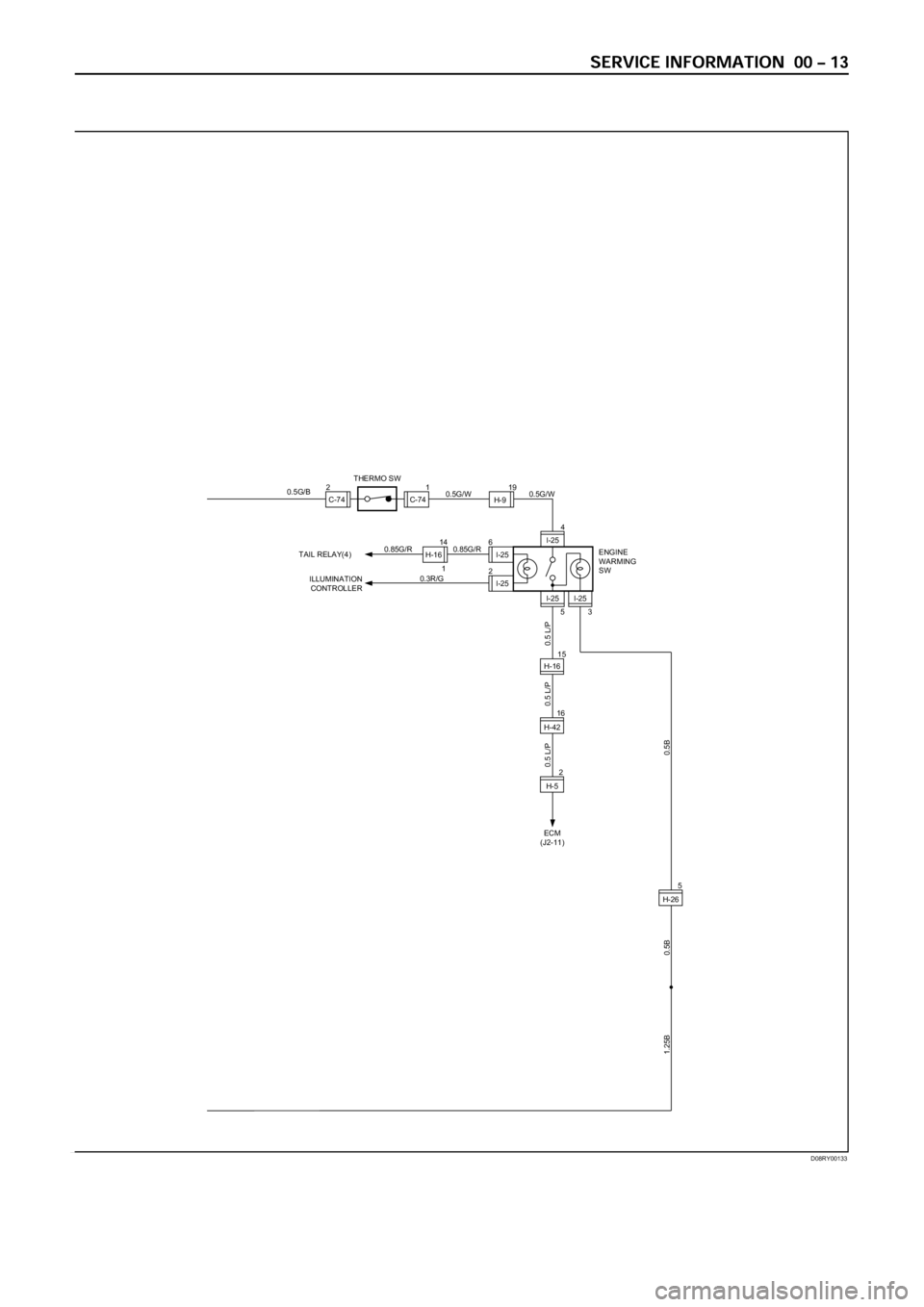
D08RY00133
ECM
(J2-11)
0.5 L/P 0.5 L/P
I-25
I-25
3
I-25 2
I-25 6
I-25
5
4
1H-1614
0.3R/G0.85G/R 0.85G/R
ILLUMINATION
CONTROLLER TAIL RELAY(4)
ENGINE
WARMING
SW
1.25B 0.5B
C-74C-741 2THERMO SWH-919
0.5G/W 0.5G/W
0.5 L/P
0.5G/B
H-265
H-4216
H-52
0.5B
H-1615
Page 54 of 6000
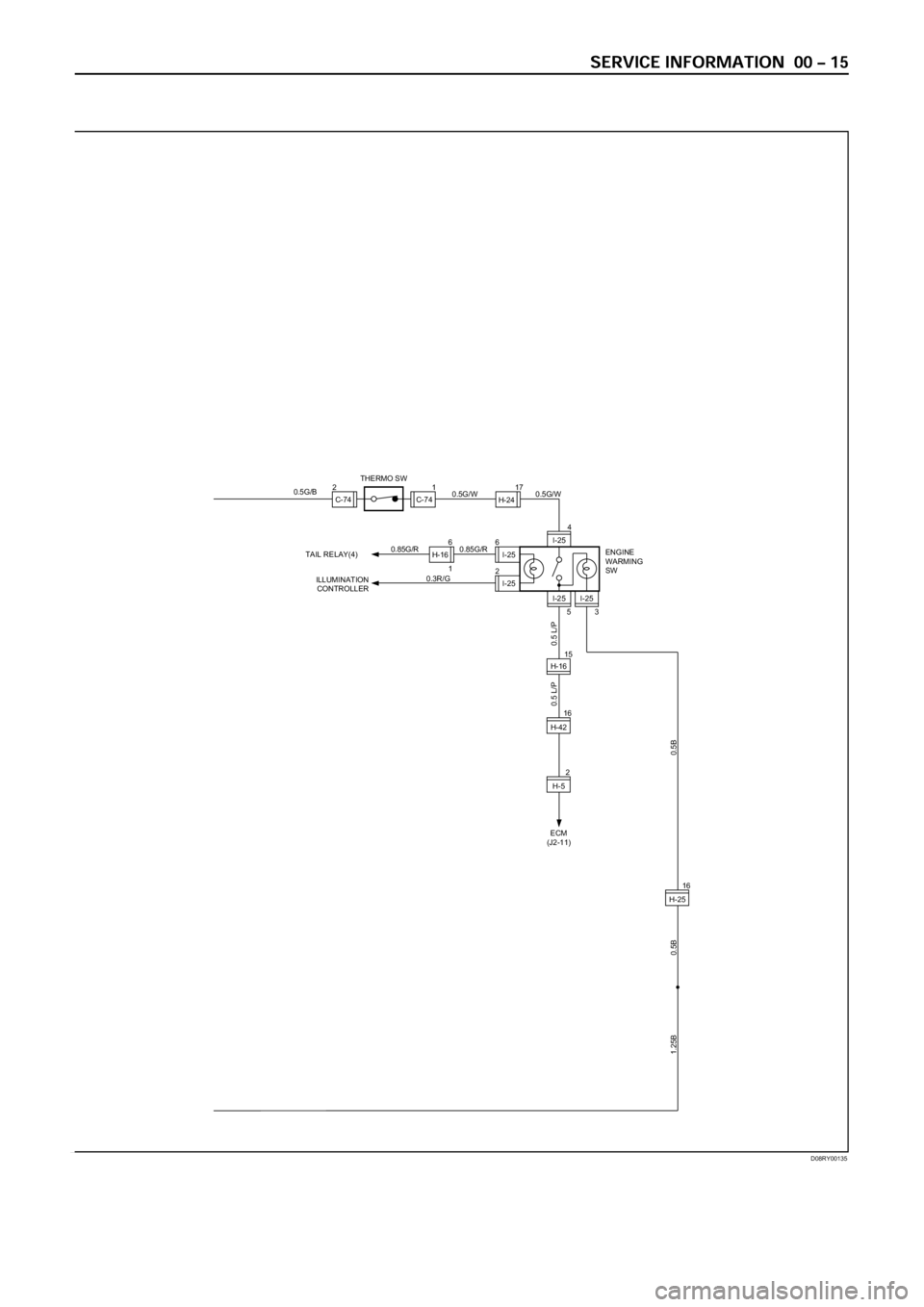
D08RY00135
ECM
(J2-11)
0.5 L/P
I-25
I-25
3
I-25 2
I-25 6
I-25
5
4
1H-166
0.3R/G0.85G/R 0.85G/R
ILLUMINATION
CONTROLLER TAIL RELAY(4)
ENGINE
WARMING
SW
1.25B 0.5B
C-74C-741 2THERMO SWH-2417
0.5G/W 0.5G/W
0.5 L/P
0.5G/B
H-2516
H-4216
H-52
0.5B
H-1615
Page 198 of 6000
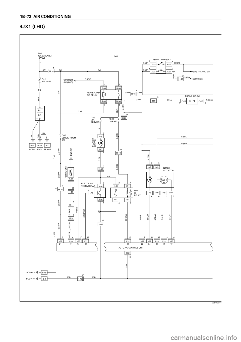
X-2124
13X-21
X-21 THERMO SW RELAY
0.5BR 0.5BR
0.5G/Y
QWS THER MO SW 0.5G/BX-21
B-2BODY-RH
B-19 BODY-LH
I-32 I-33I-32 I-32 I-33 I-33847111213
12
B-36 B-36
B-36 B-3634
7
H-26
5W 3W
5W
3L/R
C-16
CLOCK, ROOM
10AC-19
25A
BLOWERC-20
10A A/C
0.5Y/B 0.5Y/B 0.5Y/B0.5R/W 0.3R/W0.5R/W 0.5R/W
0.5BR
0.5BR0.5L/B
0.3GR/W
2B
0.3GR/L
0.5BR
HEATER AND
A/C RELAY STARTER
SW (ACC)
P-1
P-5
P-2
P-7P-10P-6
5B
2L/B30B8B
8B/R
FL-1
80A MAIN
+
ー
I-32
H-481.25B
0.5B
151.25B
I-33
7 21 14 12 2233 34 19 18 1714
I-49
4612
M
I-49 I-49 I-49
I-493
5
I-49
16
0.5L/O
0.5L/W
0.3L/R
0.3L/Y
0.3B/L
1.25B0.3B
0.5BR
C-25
I-3317I-3319
H-9
3L 2L/B
0.3BR 0.3BR
0.5BR
0.5BR
C-25
2 1 19
0.5G/W 0.5LGPRESSURE SW
INTAKE
ACTUATOR
MAX
HI
RELAY ELECTRONIC
THERMOSTAT
THERMO UNIT
H-141
I-502 0.5O/G
5W
0.3B
BODY ENG FRAME
H-167
3
H-4
E-23
1
H-9
ENGINE
0.5BR
3W/LFL-3
40A C/HEATER
2H-420.5G/Y
ECM(J1-23)
12
H-17
B-51
H-2614
I-501
B-5
2
I-50
3
15
H-48
4
H-48
MBLOWER
MOTOR
I-51
2
I-511
43I-51
I-51
AUTO A/C CONTROL UNIT
I-3212
11
H-48
D08RY00116
Page 201 of 6000

FULL AUTO display
INTAKE indication
(LED)
(switching between
fresh and interior air)
MODE indication
(LED) (Blow port)
AC display (LED)
FAN indication (LED)
FAN KNOB
AUTO SET
REC FRESH SWITCH
TEMP LEVER
(temperature control)
MODE SWITCH
(blow port selection)
AC SWITCH
IN CAR SENSOR
AMBIENT SENSOR
SUN SENSOR
DUCT SENSOR
MIX ACTUATOR
POTENTIOMETER
MODE ACTUATOR
POTENTIOMETER
AIR MIX DOOR
MODE DOOR
INTAKE ACTUATOR
RECINTAKE DOOR
FAN MOTORPOWER
TRANSISTOR
AUTOMATIC HEATER/AIR CONDITIONER CONTROL UNIT (with the built-in micro-computer)
MAX HI RELAY
PRESSURE
SWITCHAIR CONDITIONER
THERMO RELAY
COMPRESSOR
SWITCH MAGNET
CLUTCH
PCM
PRESSURE
SWITCHAIR CONDITIONER
THERMO RELAYMAGNET
CLUTCH
(4JX1engine)
MIX FRESH
F01RY00009
Page 244 of 6000
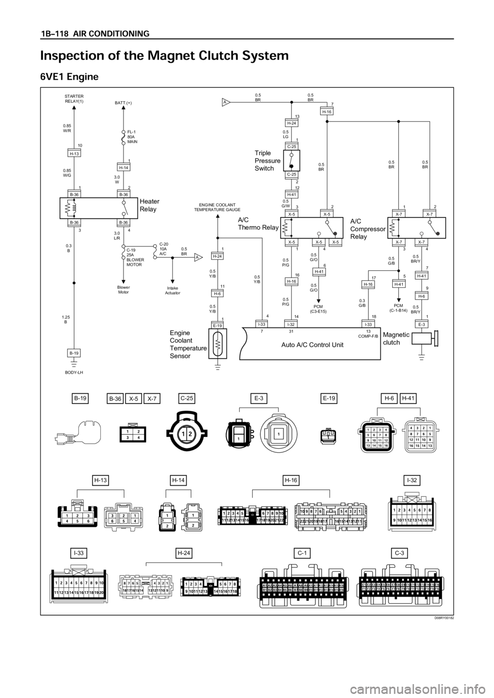
I-32
C-1C-3I-33
E-3E-19B-19C-25
A 2
B-361
H-14
C-19
25A
BLOWER
MOTOR
C-20
10A
A/C FL-1
80A
MAIN
Heater
Relay
1B-3610
H-13
0.3
B 0.85
W/G0.85
W/R
3.0
W
3.0
L/R
0.5
BR
1.25
B
B-19
BODY-LH3
B-36
4B-36
BATT.(+)
Blower
MotorIntake
Actuator STARTER
RELAY(1)
0.5
LG 0.5
BR0.5
BR
0.5
G/W
0.5
P/G0.5
P/G0.5
G/O
0.5
G/O
PCM
(C3-E15)
31 13
COMP-F/B 70.5
BR
0.5
BR/Y 0.3
G/B0.5
G/B0.5
BR/Y 0.5
BR
Triple
Pressure
Switch0.5
BR
A
A/C
Thermo Relay
Auto A/C Control Unit
3X-5
16
H-1617H-16
14
I-3218I-33
1X-5
13H-24
12
H-41
2 1
C-25
C-25
4X-5X-5 2
X-57
H-16
A/C
Compressor
Relay
Magnetic
clutch
1X-7
3X-74X-72
X-7
PCM
(C-1-B14)
E-39
1
H-67
H-41
5
H-41
Engine
Coolant
Temperature
Sensor
ENGINE COOLANT
TEMPERATURE GAUGE
0.5
Y/B
0.5
Y/B
0.5
Y/B
E-1911
1
H-61
H-24
I-334
B-36X-5X-7
H-14H-16
H-24
H-13
H-6H-41
6H-41
D08RY00182
Page 281 of 6000

1. Perform oil return operation.
2. Discharge and recover the refrigerant and remove
the compressor.
3. Drain the compressor oil and measure the extracted
oil.
4. Check the compressor oil for contamination.
5. Adjust the oil level as required.
6. Evacuate, charge and perform the oil return
operation.
7. Check the system operation.
Contamination of Compressor Oil
Unlike engine oil, no cleaning agent is added to the
compressor oil. Even if the compressor runs for a long
period of time (approximately one season), the oil never
becomes contaminated as long as there is nothing
wrong with the compressor or its method of use.
Inspect the extracted oil for any of the following
conditions:
The capacity of the oil has increased.
The oil has changed to red.
Foreign substances, metal powder, etc., are present
in the oil.
If any of these conditions exists, the compressor
oil is contaminated. Whenever contaminated
compressor oil is discovered, the receiver/drier
must be replaced.
Oil Return Operation
There is close affinity between the oil and the
refrigerant. During normal operation, part of the oil
recirculates with the refrigerant in the system. When
checking the amount of oil in the system, or replacing
any component of the system, the compressor must be
run in advance for oil return operation. The procedure
is as follows:
1. Open all the doors and the engine hood.
2. Start the engine and air conditioning switch to "ON"
and set the fan control knob at its highest position.
3. Run the compressor for more than 20 minutes
between 800 and 1,000 rpm in order to operate the
system.
4. Stop the engine.
Replacement of Component Parts
When replacing the system component parts, supply
the following amount of oil to the component parts to be
installed.
Compressor Leak Testing (External and
Internal)
Bench-Check Procedure
1. Install test plate J-39893 on rear head of compressor.
2. Using Refrigerant Recovery System, attach center
hose of manifold gage set on charging station to a
refrigerant drum standing in an upright drum.
3. Connect charging station high and low pressure
lines to corresponding fittings on test plate J-39893.
Suction port (low-side) of compressor has large
internal opening. Discharge port (high-side) has
smaller internal opening into compressor and
deeper recess.
4. Open low pressure control, high pressure control
and refrigerant control on charging station to allow
refrigerant vapor to flow into compressor.
5. Using a leak detector, check for leaks at pressure
relief valve, rear head switch location, compressor
front and rear head seals, center cylinder seal,
through bolt head gaskets and compressor shaft
seal. After checking, shut off low pressure control
and high-pressure control on charging station.
6. If an external leak is present, perform the necessary
corrective measures and recheck for leaks to make
certain the leak has been connected.
7. Recover the refrigerant.
8. Disconnect both hoses from the test plate J-39893.
9. Add 90 ml (3 oz.) new PAG lubricant to the
compressor assembly. Rotate the complete
compressor assembly (not the crankshaft or drive
plate hub) slowly several turns to distribute oil to all
cylinder and piston areas.
10. Install a M9
1.25 threaded nut on the compressor
crankshaft if the drive plate and clutch assembly are
not installed.
11. Using a box-end wrench or socket and handle,
rotate the compressor crankshaft or clutch drive
plate on the crankshaft several turns to insure
piston assembly to cylinder wall lubrication.
12. Using Refrigerant Recovery System, connect the
charging station high-pressure line to the test plate
J-39893 high-side connector.
13. Using Refrigerant Recovery System, connect the
charging station low-pressure line to the low
pressure port of the test plate J-39893. Oil will drain
out of the compressor suction port if the compressor
is positioned with the suction port downward. (Component parts to be (Amount of Oil)
installed)
Evaporator 50 cc (1.7 fl. oz.)
Condenser 30 cc (1.0 fl. oz.)
Receiver/dryer 30 cc (1.0 fl. oz.)
Refrigerant line (one 10 cc (0.3 fl. oz.)
piece)
(Amount of oil drained (Charging amount of oil
from used compressor) to new compressor)
more than 90 cc same as drained amount
(3.0 fl.oz)
less than 90 cc (3.0 fl.oz) 90 cc (3.0 fl.oz)
Page 469 of 6000
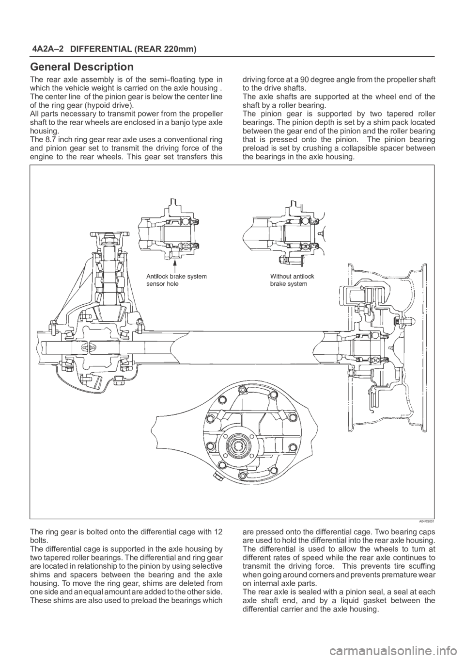
4A2A–2
DIFFERENTIAL (REAR 220mm)
General Description
The rear axle assembly is of the semi–floating type in
which the vehicle weight is carried on the axle housing .
The center line of the pinion gear is below the center line
of the ring gear (hypoid drive).
All parts necessary to transmit power from the propeller
shaft to the rear wheels are enclosed in a banjo type axle
housing.
The 8.7 inch ring gear rear axle uses a conventional ring
and pinion gear set to transmit the driving force of the
engine to the rear wheels. This gear set transfers thisdriving force at a 90 degree angle from the propeller shaft
to the drive shafts.
The axle shafts are supported at the wheel end of the
shaft by a roller bearing.
The pinion gear is supported by two tapered roller
bearings. The pinion depth is set by a shim pack located
between the gear end of the pinion and the roller bearing
that is pressed onto the pinion. The pinion bearing
preload is set by crushing a collapsible spacer between
the bearings in the axle housing.
A04RS001
The ring gear is bolted onto the differential cage with 12
bolts.
The differential cage is supported in the axle housing by
two tapered roller bearings. The differential and ring gear
are located in relationship to the pinion by using selective
shims and spacers between the bearing and the axle
housing. To move the ring gear, shims are deleted from
one side and an equal amount are added to the other side.
These shims are also used to preload the bearings whichare pressed onto the differential cage. Two bearing caps
are used to hold the differential into the rear axle housing.
The differential is used to allow the wheels to turn at
different rates of speed while the rear axle continues to
transmit the driving force. This prevents tire scuffing
when going around corners and prevents premature wear
on internal axle parts.
The rear axle is sealed with a pinion seal, a seal at each
axle shaft end, and by a liquid gasket between the
differential carrier and the axle housing.
Page 470 of 6000
DIFFERENTIAL (REAR 220mm)
4A2A–3
Diagnosis
Many noises that seem to come from the rear axle
actually originate from other sources such as tires, road
surface, wheel bearings, engine, transmission, muffler, or
body drumming. Investigate to find the source of the
noise before disassembling the rear axle. Rear axles, like
any other mechanical device, are not absolutely quiet but
should be considered quiet unless some abnormal noise
is present.
To make a systematic check for axle noise, observe the
following:
1. Select a level asphalt road to reduce tire noise and
body drumming.
2. Check rear axle lubricant level to assure correct level,
and then drive the vehicle far enough to thoroughly
warm up the rear axle lubricant.
3. Note the speed at which noise occurs. Stop the
vehicle and put the transmission in neutral. Run the
engine speed slowly up and down to determine if the
noise is caused by exhaust, muffler noise, or other
engine conditions.
4. Tire noise changes with different road surfaces; axle
noises do not. Temporarily inflate all tires to 344 kPa
(3.5kg/cm
2, 50 psi) (for test purposes only). This will
change noise caused by tires but will not affect noise
caused by the rear axle.
Rear axle noise usually stops when coasting at
speeds under 48 km/h (30 mph); however, tire noise
continues with a lower tone. Rear axle noise usually
changes when comparing pull and coast, but tire
noise stays about the same.
Distinguish between tire noise and rear axle noise by
noting if the noise changes with various speeds or
sudden acceleration and deceleration. Exhaust and
axle noise vary under these conditions, while tire
noise remains constant and is more pronounced at
speeds of 32 to 48 km/h (20 to 30 mph). Further check
for tire noise by driving the vehicle over smooth
pavements or dirt roads (not gravel) with the tires at
normal pressure. If the noise is caused by tires, it will
change noticeably with changes in road surface.
5. Loose or rough front wheel bearings will cause noise
which may be confused with rear axle noise; however,
front wheel bearing noise does not change when
comparing drive and coast. Light application of the
brake while holding vehicle speed steady will often
cause wheel bearing noise to diminish. Front wheel
bearings may be checked for noise by jacking up the
wheels and spinning them or by shaking the wheels to
determine if bearings are loose.
6. Rear suspension rubber bushings and spring
insulators dampen out rear axle noise when correctly
installed. Check to see that there is no link or rod
loosened or metal–to–metal contact.
7. Make sure that there is no metal–to–metal contact
between the floor and the frame.
After the noise has been determined to be in the axle, the
type of axle noise should be determined, in order to make
any necessary repairs.
Gear Noise
Gear noise (whine) is audible from 32 to 89 km/h (20 to 55
mph) under four driving conditions.
1. Driving under acceleration or heavy pull.
2. Driving under load or under constant speed.
3. When using enough throttle to keep the vehicle from
driving the engine while the vehicle slows down
gradually (engine still pulls slightly).
4. When coasting with the vehicle in gear and the throttle
closed. The gear noise is usually more noticeable
between 48 and 64 km/h (30 and 40 mph) and 80 and
89 km/h (50 and 55 mph).
Bearing Noise
Bad bearings generally produce a rough growl or grating
sound, rather than the whine typical of gear noise.
Bearing noise frequently “wow–wows” at bearing rpm,
indicating a bad pinion or rear axle side bearing. This
noise can be confused with rear wheel bearing noise.
Rear Wheel Bearing Noise
Rear wheel bearing noise continues to be heard while
coasting at low speed with transmission in neutral. Noise
may diminish by gentle braking. Jack up the rear wheels,
spin them by hand and listen for noise at the hubs.
Replace any faulty wheel bearings.
Knock At Low Speeds
Low speed knock can be caused by worn universal joints
or a side gear hub counter bore in the cage that is worn
oversize. Inspect and replace universal joints or cage and
side gears as required.
Backlash Clunk
Excessive clunk on acceleration and deceleration can be
caused by a worn rear axle pinion shaft, a worn cage,
excessive clearance between the axle and the side gear
splines, excessive clearance between the side gear hub
and the counterbore in the cage, worn pinion and side
gear teeth, worn thrust washers, or excessive drive pinion
and ring gear backlash. Remove worn parts and replace
as required. Select close–fitting parts when possible.
Adjust pinion and ring gear backlash.