coolant level OPEL FRONTERA 1998 Workshop Manual
[x] Cancel search | Manufacturer: OPEL, Model Year: 1998, Model line: FRONTERA, Model: OPEL FRONTERA 1998Pages: 6000, PDF Size: 97 MB
Page 967 of 6000
6A–11
ENGINE MECHANICAL
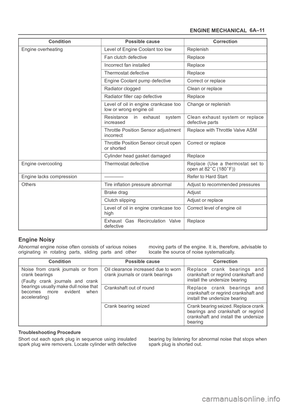
Condition CorrectionPossible cause
Engine overheatingLevel of Engine Coolant too lowReplenish
Fan clutch defectiveReplace
Incorrect fan installedReplace
Thermostat defectiveReplace
Engine Coolant pump defectiveCorrect or replace
Radiator cloggedClean or replace
Radiator filler cap defectiveReplace
Level of oil in engine crankcase too
low or wrong engine oilChange or replenish
Resistance in exhaust system
increasedClean exhaust system or replace
defective parts
Throttle Position Sensor adjustment
incorrectReplace with Throttle Valve ASM
Throttle Position Sensor circuit open
or shortedCorrect or replace
Cylinder head gasket damagedReplace
Engine overcoolingThermostat defectiveReplace (Use a thermostat set to
open at 82
C (180F))
Engine lacks compression————Refer to Hard Start
OthersTire inflation pressure abnormalAdjust to recommended pressures
Brake dragAdjust
Clutch slippingAdjust or replace
Level of oil in engine crankcase too
highCorrect level of engine oil
Exhaust Gas Recirculation Valve
defectiveReplace
Engine Noisy
Abnormal engine noise often consists of various noises
originating in rotating parts, sliding parts and othermoving parts of the engine. It is, therefore, advisable to
locate the source of noise systematically.
Condition
Possible causeCorrection
Noise from crank journals or from
crank bearings
(Faulty crank journals and crankOil clearance increased due to worn
crank journals or crank bearingsReplace crank bearings and
crankshaft or regrind crankshaft and
install the undersize bearing
yj
bearings usually make dull noise that
becomes more evident when
accelerating)Crankshaft out of roundReplace crank bearings and
crankshaft or regrind crankshaft and
install the undersize bearing
Crank bearing seizedCrank bearing seized. Replace crank
bearings and crankshaft or regrind
crankshaft and install the undersize
bearing
Troubleshooting Procedure
Short out each spark plug in sequence using insulated
spark plug wire removers. Locate cylinder with defectivebearing by listening for abnormal noise that stops when
spark plug is shorted out.
Page 995 of 6000

6A–39
ENGINE MECHANICAL
Valve Stem Oil Controller , Valve Spring and Valve Guide
Removal
1. Disconnect battery ground cable.
2. Drain engine oil.
Drain engine coolant.
3. Remove cylinder head assembly.
Refer to removal procedure for Cylinder Head in
this manual.
4. Remove camshaft.
Refer to removal procedure for Camshaft in this
manual.
5. Remove tappets with shim.
NOTE: Do not damage shim surface.
6. Remove valve springs using 5–8840–2446–0 valve
spring compressor and 5–8840–2547–0 valve spring
compressor adapter then remove upper valve spring
seat and lower seat.
014RW042
7. Remove oil controller using 5–8840–0623–0 oil
controller remover, remove each valve stem oil
controller.
8. Remove valve guide using 5–8840–2549–0 valve
guide replacer.
Installation
1. Install valve guide using 5–8840–2442–0 valve guide
installer.
2. Install oil controller using 5–8840–0624–0 oil
controller installer.
3. Install lower valve spring seat, valve spring and upper
valve spring seat then put split collars on the upper
spring seat, using 5–8840–2446–0 valve spring
compressor and 5–8840–2547–0 valve spring
compressor adapter to install the split collars.
014RW042
4. Install tappet with shim.
5. Install camshaft assembly.
Refer to installation procedure for Camshaft in this
manual.
6. Install cylinder head assembly.
Refer to installation procedure for Cylinder Head in
this manual.
7. Fill engine oil until full level.
8. Fill engine coolant.
Page 1058 of 6000
ENGINE COOLING6B–5
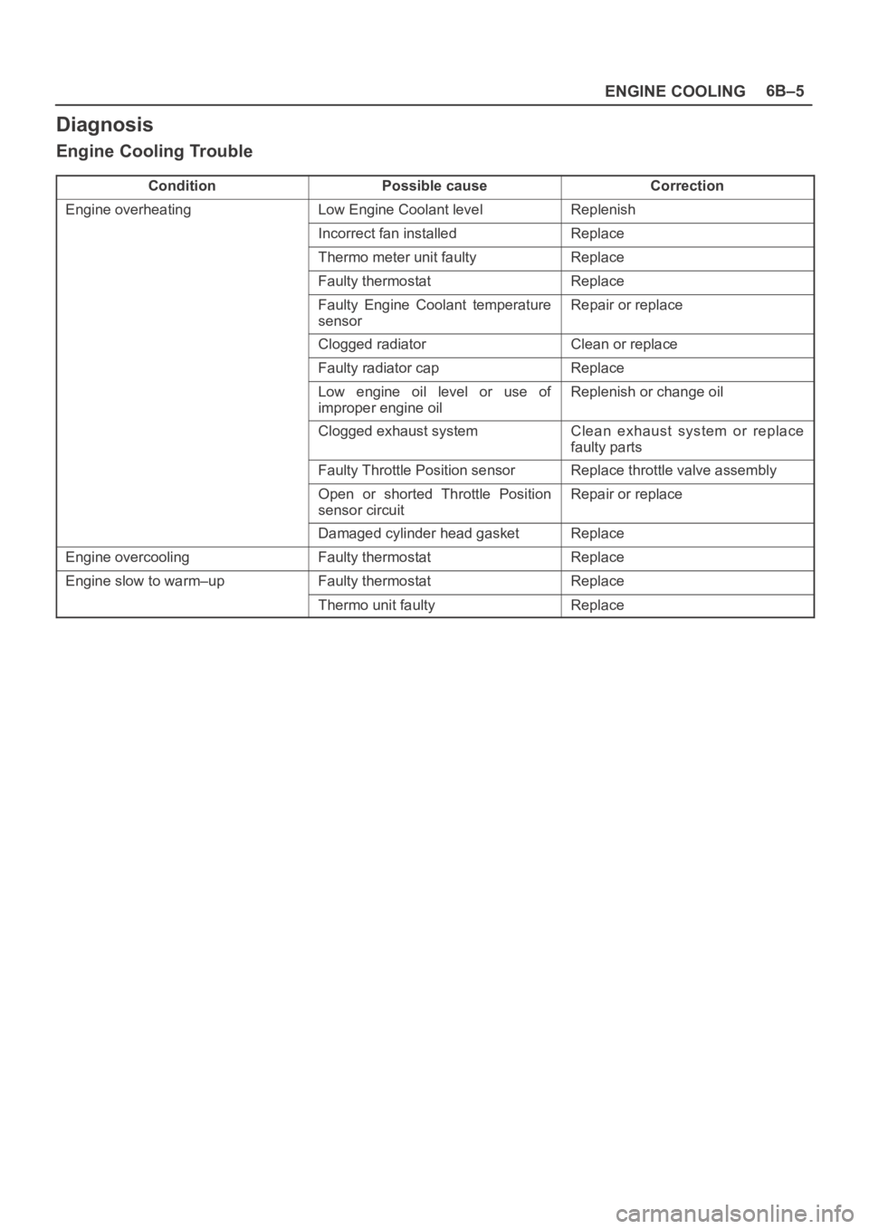
Diagnosis
Engine Cooling Trouble
ConditionPossible causeCorrection
Engine overheatingLow Engine Coolant levelReplenish
Incorrect fan installedReplace
Thermo meter unit faultyReplace
Faulty thermostatReplace
Faulty Engine Coolant temperature
sensorRepair or replace
Clogged radiatorClean or replace
Faulty radiator capReplace
Low engine oil level or use of
improper engine oilReplenish or change oil
Clogged exhaust systemClean exhaust system or replace
faulty parts
Faulty Throttle Position sensorReplace throttle valve assembly
Open or shorted Throttle Position
sensor circuitRepair or replace
Damaged cylinder head gasketReplace
Engine overcoolingFaulty thermostatReplace
Engine slow to warm–upFaulty thermostatReplace
Thermo unit faultyReplace
Page 1059 of 6000
6B–6
ENGINE COOLING
Draining and Refilling Cooling
System
Before draining the cooling system, inspect the system
and perform any necessary service to ensure that it is
clean, does not leak and is in proper working order. The
engine coolant (EC) level should be between the “MIN”
and “MAX” lines of reserve tank when the engine is cold.
If low, check for leakage and add EC up to the “MAX” line.
There should not be any excessive deposit of rust or
scales around the radiator cap or radiator filler hole, and
the EC should also be free from oil.
Replace the EC if excessively dirty.
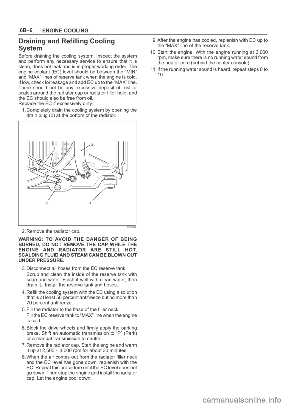
1. Completely drain the cooling system by opening the
drain plug (2) at the bottom of the radiator.
110RW002
2. Remove the radiator cap.
WARNING: TO AVOID THE DANGER OF BEING
BURNED, DO NOT REMOVE THE CAP WHILE THE
ENGINE AND RADIATOR ARE STILL HOT.
SCALDING FLUID AND STEAM CAN BE BLOWN OUT
UNDER PRESSURE.
3. Disconnect all hoses from the EC reserve tank.
Scrub and clean the inside of the reserve tank with
soap and water. Flush it well with clean water, then
drain it. Install the reserve tank and hoses.
4. Refill the cooling system with the EC using a solution
that is at least 50 percent antifreeze but no more than
70 percent antifreeze.
5. Fill the radiator to the base of the filler neck.
Fill the EC reserve tank to “MAX” line when the engine
is cold.
6. Block the drive wheels and firmly apply the parking
brake. Shift an automatic transmission to “P” (Park)
or a manual transmission to neutral.
7. Remove the radiator cap. Start the engine and warm
it up at 2,500
3,000 rpm for about 30 minutes.
8. When the air comes out from the radiator filler neck
and the EC level has gone down, replenish with the
EC. Repeat this procedure until the EC level does not
go down. Then stop the engine and install the radiator
cap. Let the engine cool down.9. After the engine has cooled, replenish with EC up to
the “MAX” line of the reserve tank.
10. Start the engine. With the engine running at 3,000
rpm, make sure there is no running water sound from
the heater core (behind the center console).
11. If the running water sound is heard, repeat steps 8 to
10.
Page 1064 of 6000
ENGINE COOLING6B–11
Cap tester: 5–8840–0277–0
Adapter: 5–8840–2603–0
110RS005
Installation
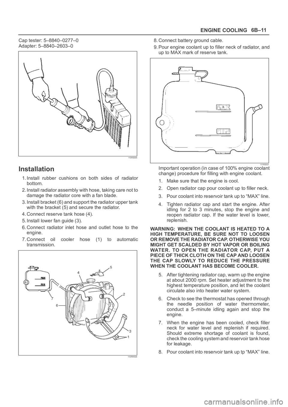
1. Install rubber cushions on both sides of radiator
bottom.
2. Install radiator assembly with hose, taking care not to
damage the radiator core with a fan blade.
3. Install bracket (6) and support the radiator upper tank
with the bracket (5) and secure the radiator.
4. Connect reserve tank hose (4).
5. Install lower fan guide (3).
6. Connect radiator inlet hose and outlet hose to the
engine.
7. Connect oil cooler hose (1) to automatic
transmission.
110RW004
8. Connect battery ground cable.
9. Pour engine coolant up to filler neck of radiator, and
up to MAX mark of reserve tank.
111 R S 0 0 1Important operation (in case of 100% engine coolant
change) procedure for filling with engine coolant.
1. Make sure that the engine is cool.
2. Open radiator cap pour coolant up to filler neck.
3. Pour coolant into reservoir tank up to “MAX” line.
4. Tighten radiator cap and start the engine. After
idling for 2 to 3 minutes, stop the engine and
reopen radiator cap. If the water level is lower,
replenish.
WARNING: WHEN THE COOLANT IS HEATED TO A
HIGH TEMPERATURE, BE SURE NOT TO LOOSEN
OR REMOVE THE RADIATOR CAP. OTHERWISE YOU
MIGHT GET SCALDED BY HOT VAPOR OR BOILING
WATER. TO OPEN THE RADIATOR CAP, PUT A
PIECE OF THICK CLOTH ON THE CAP AND LOOSEN
THE CAP SLOWLY TO REDUCE THE PRESSURE
WHEN THE COOLANT HAS BECOME COOLER.
5. After tightening radiator cap, warm up the engine
at about 2000 rpm. Set heater adjustment to the
highest temperature position, and let the coolant
circulate also into heater water system.
6. Check to see the thermostat has opened through
the needle position of water thermometer,
conduct a 5–minute idling again and stop the
engine.
7. When the engine has been cooled, check filler
neck for water level and replenish if required.
Should extreme shortage of coolant is found,
check the cooling system and reservoir tank hose
for leakage.
8. Pour coolant into reservoir tank up tp “MAX” line.
Page 1156 of 6000
6E–39 ENGINE DRIVEABILITY AND EMISSIONS
The data displayed on the other Tech 2 will appear the
same, with some exceptions. Some Tech 2s will only be
able to display certain vehicle parameters as values that
are a coded representation of the true or actual value. For
more information on this system of coding, refer to
Decimal/Binary/Hexadecimal Conversions. On this
vehicle Tech 2 displays the actual values for vehicle
parameters. It will not be necessary to perform any
conversions from coded values to actual values.
On-Board Diagnostic (OBD)
On-Board Diagnostic Tests
A diagnostic test is a series of steps, the result of which is
a pass or fail reported to the diagnostic executive. When
a diagnostic test reports a pass result, the diagnostic
executive records the following data:
The diagnostic test has been completed since the last
ignition cycle.
The diagnostic test has passed during the current
ignition cycle.
The fault identified by the diagnostic test is not
currently active.
W h e n a d i a g n o s t i c t e s t r e p o r t s a fail result, the diagnostic
executive records the following data:
The diagnostic test has been completed since the last
ignition cycle.
The fault identified by the diagnostic test is currently
active.
The fault has been active during this ignition cycle.
The operating conditions at the time of the failure.
Remember, a fuel trim DTC may be triggered by a list of
vehicle faults. Make use of all information available (other
DTCs stored, rich or lean condition, etc.) when
diagnosing a fuel trim fault.
Comprehensive Component Monitor
Diagnostic Operation
Input Components:
Input components are monitored for circuit continuity and
out-of-range values. This includes rationality checking.
Rationality checking refers to indicating a fault when the
signal from a sensor does not seem reasonable, i.e.
Throttle Position (TP) sensor that indicates high throttle
position at low engine loads or MAP voltage. Input
components may include, but are not limited to the
following sensors:
Vehicle Speed Sensor (VSS)
Crankshaft Position (CKP) sensor
Knock Sensor (KS)
Throttle Position (TP) sensor
Engine Coolant Temperature (ECT) sensor
Camshaft Position (CMP) sensor
Manifold Absolute Pressure (MAP) sensor
Mass Air Flow (MAF) sensorIn addition to the circuit continuity and rationality check,
the ECT sensor is monitored for its ability to achieve a
steady state temperature to enable closed loop fuel
control.
Output Components:
Output components are diagnosed for proper response to
control module commands. Components where
functional monitoring is not feasible will be monitored for
circuit continuity and out-of-range values if applicable.
Output components to be monitored include, but are not
limited to, the following circuits:
Idle Air Control (IAC) Motor
Electronic Transmission controls
A/C relays
Cooling fan relay
VSS output
MIL control
Cruise control inhibit
Refer to PCM and Sensors in General Descriptions.
Passive and Active Diagnostic Tests
A passive test is a diagnostic test which simply monitors a
vehicle system or component. Conversely, an active test,
actually takes some sort of action when performing
diagnostic functions, often in response to a failed passive
test. For example, the EGR diagnostic active test will
force the EGR valve open during closed throttle decel
and/or force the EGR valve closed during a steady state.
Either action should result in a change in manifold
pressure.
Intrusive Diagnostic Tests
This is any on-board test run by the Diagnostic
Management System which may have an effect on
vehicle performance or emission levels.
Warm-Up Cycle
A warm-up cycle means that engine at temperature must
reach a minimum of 70
C (160F) and rise at least 22C
(40
F) over the course of a trip.
Freeze Frame
Freeze Frame is an element of the Diagnostic
Management System which stores various vehicle
information at the moment an emissions-related fault is
stored in memory and when the MIL is commanded on.
These data can help to identify the cause of a fault. Refer
to
Storing And Erasing Freeze Fame Data for more
detailed information.
Failure Records
Failure Records data is an enhancement of the OBD
Freeze Frame feature. Failure Records store the same
vehicle information as does Freeze Frame, but it will store
that information for any fault which is stored in on-board
memory, while Freeze Frame stores information only for
emission-related faults that command the MIL on.
Page 1158 of 6000
6E–41 ENGINE DRIVEABILITY AND EMISSIONS
If the MIL was set by either a fuel trim or misfire-related
DTC, additional requirements must be met. In addition to
the requirements stated in the previous paragraph, these
requirements are as follows:
The diagnostic tests that are passed must occur with
375 RPM of the RPM data stored at the time the last
test failed.
Plus or minus ten (10) percent of the engine load that
was stored at the time the last failed.
Similar engine temperature conditions (warmed up or
warming up ) as those stored at the time the last test
failed.
Meeting these requirements ensures that the fault which
turned on the MIL has been corrected.
The MIL (“Check Engine” lamp) is on the instrument
panel and has the following function:
It informs the driver that a fault affects vehicle emission
levels has occurred and that the vehicle should be
taken for service as soon as possible.
As a bulb and system check, the MIL will come “ON”
with the key “ON” and the engine not running. When
the engine is started, the MIL will turn “OFF.”
When the MIL remains “ON” while the engine is
running, or when a malfunction is suspected due to a
driveability or emissions problem, a Powertrain
On-Board Diagnostic (OBD ll) System Check must be
performed. The procedures for these checks are given
in On-Board Diagnostic (OBD) System Check. These
checks will expose faults which may not be detected if
other diagnostics are performed first.
DTC Types
Each DTC is directly related to a diagnostic test. The
Diagnostic Management System sets DTC based on the
failure of the tests during a trip or trips. Certain tests must
fail two (2) consecutive trips before the DTC is set. The
following are the four (4) types of DTCs and the
characteristics of those codes:
Ty p e A
Emissions related
Requests illumination of the MIL of the first trip with a
fail
Stores a History DTC on the first trip with a fail
Stores a Freeze Frame (if empty)
Stores a Fail Record
Updates the Fail Record each time the diagnostic
test fails
Ty p e B
Emissions related
“Armed” after one (1) trip with a fail
“Disarmed” after one (1) trip with a pass
Requests illumination of the MIL on the second
consecutive trip
with a fail
Stores a History DTC on the second consecutive trip
with a fail (The DTC will be armed after the first fail)
Stores a Freeze Frame on the second consecutive
trip with a fail (if empty)
Stores a Fail Record when the first test fails (not
dependent on
consecutive trip fails)
Updates the Fail Record each time the diagnostic
test fails
Type C (if the vehicle is so equipped)
Non-Emissions related
Requests illumination of the Service Lamp or the
service message on the Drive Information Center
(DIC) on the
first trip with a fail
Stores a History DTC on the first trip with a fail
Does not store a Freeze Frame
Stores Fail Record when test fails
Updates the Fail Record each time the diagnostic
test fails
Type D (Ty p e D non-emissions related are not utilized
on certain vehicle applications).
Non-Emissions related
Dose not request illumination of any lamp
Stores a History DTC on the first trip with a fail
Does not store a Freeze Frame
Stores Fail Record when test fails
Updates the Fail Record each time the diagnostic
test fails
IMPORTANT:Only four Fail Records can be stored.
Each Fail Record is for a different DTC. It is possible that
there will not be Fail Records for every DTC if multiple
DTCs are set.
Storing and Erasing Freeze Frame Data and Failure
Records
The data captured is called Freeze Frame data. The
Freeze Frame data is very similar to a single record of
operating conditions. Whenever the MIL is illuminated,
the corresponding record of operating conditions is
recorded to the Freeze Frame buffer.
Data from these faults take precedence over data
associated with any other fault. The Freeze Frame data
will not be erased unless the associated history DTC is
cleared.
Each time a diagnostic test reports a failure, the current
engine operating conditions are recorded in the
Failure
Records
buffer. A subsequent failure will update the
recorded operating conditions. The following operating
conditions for the diagnostic test which failed
typically
include the following parameters:
Air Fuel Ratio
Air Flow Rate
Fuel Trim
Engine Speed
Engine Load
Engine Coolant Temperature
Vehicle Speed
TP Angle
MAP/BARO
Injector Base Pulse Width
Loop Status
Page 1182 of 6000
6E–65 ENGINE DRIVEABILITY AND EMISSIONS
Knock Sensor Diagnosis
The Tech 2 has two data displays available for diagnosing
the knock sensor (KS) system. The two displays are
described as follows:
“Knock Retard” indicates the number of degrees that
the spark timing is being retarded due to a knock
condition.
“KS Noise Channel” indicates the current voltage level
being monitored on the noise channel.
DTCs P0325 and P0327 are designed to diagnose the KS
module, the knock sensor, and the related wiring. The
problems encountered with the KS system should set a
DTC. However, if no DTC was set but the KS system is
suspect because of a detonation complaint, refer to
Detonation/Spark Knock in Symptoms.
Powertrain Control Module (PCM)
Diagnosis
To read and clear diagnostic trouble codes, use a Tech 2.
IMPORTANT:Use of a Tech 2 is recommended to clear
diagnostic trouble codes from the PCM memory.
Diagnostic trouble codes can also be cleared by turning
the ignition “OFF” and disconnecting the battery power
from the PCM for 30 seconds. Turning off the ignition and
disconnecting the battery power from the PCM will cause
all diagnostic information in the PCM memory to be
cleared. Therefore, all the diagnostic tests will have to be
re-run.
Since the PCM can have a failure which may affect only
one circuit, following the diagnostic procedures in this
section will determine which circuit has a problem and
where it is.
If a diagnostic chart indicates that the PCM connections
or the PCM is the cause of a problem, and the PCM is
replaced, but this does not correct the problem, one of the
following may be the reason:
There is a problem with the PCM terminal connections.
The terminals may have to be removed from the
connector in order to check them properly.
The problem is intermittent. This means that the
problem is not present at the time the system is being
checked. In this case, refer to the
Symptoms p o r t i o n o f
the manual and make a careful physical inspection of
all component and wiring associated with the affected
system.
There is a shorted solenoid, relay coil, or harness.
S o l e n o i d s a n d r e l a y s a r e t u r n e d “ O N ” a n d “ O F F ” b y t h e
PCM using internal electronic switches called drivers.
A shorted solenoid, relay coil, or harness will not
damage the PCM but will cause the solenoid or relay to
be inoperative.
Multiple PCM Information Sensor
DTCS Set
Circuit Description
The powertrain control module (PCM) monitors various
sensors to determine the engine operating conditions.
The PCM controls fuel delivery, spark advance,
transmission operation, and emission control device
operation based on the sensor inputs.The PCM provides a sensor ground to all of the sensors.
The PCM applies 5 volts through a pull-up resistor, and
determines the status of the following sensors by
monitoring the voltage present between the 5-volt supply
and the resistor:
The engine coolant temperature (ETC) sensor
The intake air temperature (IAT) sensor
The transmission fluid temperature (TFT) sensor
The PCM provides the following sensors with a 5-volt
reference and a sensor ground signal:
The exhaust gas recirculating (EGR) pintle position
sensor
The throttle position (TP) sensor
The manifold absolute pressure (MAP) sensor
The PCM monitors the separate feedback signals from
these sensors in order to determine their operating
status.
Diagnostic Aids
IMPORTANT:Be sure to inspect PCM and engine
grounds for being secure and clean.
A short to voltage in one of the sensor input circuits may
cause one or more of the following DTCs to be set:
P0108
P0113
P0118
P0123
P0560
P0712
P0406
IMPORTANT:If a sensor input circuit has been shorted
to voltage, ensure that the sensor is not damaged. A
damaged sensor will continue to indicate a high or low
voltage after the affected circuit has been repaired. If the
sensor has been damaged, replace it.
An open in the sensor ground circuit between the PCM
and the splice will cause one or more of the following
DTCs to be set:
P0108
P0113
P0118
P0123
P0712
P0406
A short to ground in the 5-volt reference A or B circuit will
cause one or more of the following DTCs to be set:
P0107
P0122
In the 5-volt reference circuit A, between the PCM and the
splice, will cause one or more of the following DTCs to be
set:
P0122
In the 5-volt reference circuit B, between the PCM and the
splice, will cause one or more of the following DTCs to be
set:
P0107
Check for the following conditions:
Page 1392 of 6000

6E–275 ENGINE DRIVEABILITY AND EMISSIONS
Poor Fuel Economy Symptom
StepActionVa l u e ( s )Ye sNo
1DEFINITION:
Fuel economy, as measured by an actual road test, is
noticeably lower than expected. Also, economy is
noticeably lower than it was on this vehicle at one time,
as previously shown by an actual road test.
(Non-standard tires will cause odometer readings to be
incorrect, and that may cause fuel economy to appear
poor when it is actually normal.)
Was the “On-Board Diagnostic (OBD) System Check”
performed?
—Go to Step 2
Go to OBD
System
Check
21. Perform a bulletin search.
2. If a bulletin that addresses the symptom is found,
correct the condition as instructed in the bulletin.
Was a bulletin found that addresses the symptom?
—Verify repairGo to Step 3
3Was a visual/physical check performed?
—Go to Step 4
Go to
Visual/Physic
al Check
4Check owner’s driving habits.
Is the A/C “ON” full time (defroster mode “ON”)?
Are tires at the correct pressure?
Are excessively heavy loads being carried?
Is acceleration too much, too often?
Was a problem found?
—Go to Step 5Go to Step 6
5Review the items in Step 4 with the customer and
advise as necessary.
Is the action complete?
—System OK—
61. Visually/physically check: Vacuum hoses for splits,
kinks, and improper connections and routing as
shown on the “Vehicle Emission Control
Information” label.
2. If a problem is found, repair as necessary.
Was a problem found?
—Verify repairGo to Step 7
71. Remove and check the air filter element for dirt or for
restrictions. Refer to
Air Intake System.
2. Replace the air filter element if necessary.
Was a repair required?
—Verify repairGo to Step 8
81. Remove spark plugs and check for wet plugs,
cracks, wear, improper gap, burned electrodes, or
heavy deposits. Refer to
Spark Plug Replacement.
NOTE: If spark plugs are gas or oil fouled, the cause of
the fouling must be determined before replacing the
spark plugs.
2. If a problem is found, repair as necessary.
Was a problem found?
—Verify repairGo to Step 9
91. Check for low engine coolant level. Refer to Engine
Cooling
.
2. If a problem is found, repair as necessary.
Was a problem found?
—Verify repairGo to Step 10
Page 1454 of 6000
6E–337 ENGINE DRIVEABILITY AND EMISSIONS
0018
Knock Sensor
Insufficient gasoline octane levels may cause detonation
in some engines. Detonation is an uncontrolled explosion
(burn) in the combustion chamber. This uncontrolled
explosion results from a flame front opposite that of the
normal flame front produced by the spark plug. The
rattling sound normally associated with detonation is the
result of two or more opposing pressures (flame fronts)
colliding within the combustion chamber. Light
detonation is sometimes considered normal, but heavy
detonation could result in engine damage.
A knock sensor system is used to control detonation. This
system is designed to retard spark timing up to 20
degrees to reduce detonation in the engine. This allows
the engine to use maximum spark advance to improve
driveability and fuel economy.
The knock sensor system has two major components:
The knock sensor (KS) module.
The knock sensor.
The knock sensor, mounted in the engine block near the
cylinders, detects abnormal vibration in the engine. The
sensor produces an AC output signal of about 10
millivolts. The signal amplitude and frequency are
dependent on the amount of knock being experienced.
The signal voltage increases with the severity of the
knock. This signal voltage is input to the PCM. The PCM
then retards the ignition control (IC) spark timing based
on the KS signal being received.
The PCM determines whether knock is occurring by
comparing the signal level on the KS circuit with the
voltage level on the noise channel. The noise channel
allows the PCM to reject any false knock signal by
indicating the amount of normal engine mechanical noise
present. Normal engine noise varies depending on the
engine speed and load. If the voltage level on the KS
noise channel circuit is below the range considered
normal, DTC P0327 will set, indicating a fault in the KScircuit or the knock sensor. If the PCM determines that an
abnormal minimum or maximum noise level is being
experienced, DTC P0325 will set.
The PCM contains a knock sensor (KS) module. The KS
module contains the circuitry which allows the PCM to
utilize the KS signal and diagnose the KS sensor and the
KS circuitry. If the KS module is missing or faulty, a
continuous knock condition will be indicated, and the
PCM will set DTC P0325.
Although it is a plug-in device, the KS module is not
replaceable. If the KS module is faulty, the entire PCM
must be replaced.
0009
Linear Exhaust Gas Recirculation (EGR)
Control
The PCM monitors the exhaust gas recirculation (EGR)
actual position and adjusts the pintle position accordingly.
The PCM uses information from the following sensors to
control the pintle position:
Engine coolant temperature (ECT) sensor.
Throttle position (TP) sensor.
Mass air flow (MAF) sensor.
Mass Air Flow (MAF) Sensor
The mass air flow (MAF) sensor measures the difference
between the volume and the quantity of air that enters the
engine. “Volume” means the size of the space to be filled.
“Quantity” means the number of air molecules that will fit
into the space. This information is important to the PCM
because heavier, denser air will hold more fuel than
lighter, thinner air. The PCM adjusts the air/fuel ratio as
needed depending on the MAF value. Tech 2 reads the
MAF value and displays it in terms of grams per second
(gm/s). At idle, Tech 2 should read between 4-7 gm/s on a
fully warmed up engine. Values should change quickly on
acceleration. Values should remain stable at any given