coolant capacity OPEL FRONTERA 1998 Workshop Manual
[x] Cancel search | Manufacturer: OPEL, Model Year: 1998, Model line: FRONTERA, Model: OPEL FRONTERA 1998Pages: 6000, PDF Size: 97 MB
Page 1057 of 6000
6B–4
ENGINE COOLING
NOTE: Antifreeze solution + Water = Total cooling
system capacity.
Total Cooling System Capacity
M/T 8.8Lit (2.32Us gal)
A/T 8.4Lit (2.22Us gal)
B06RW002
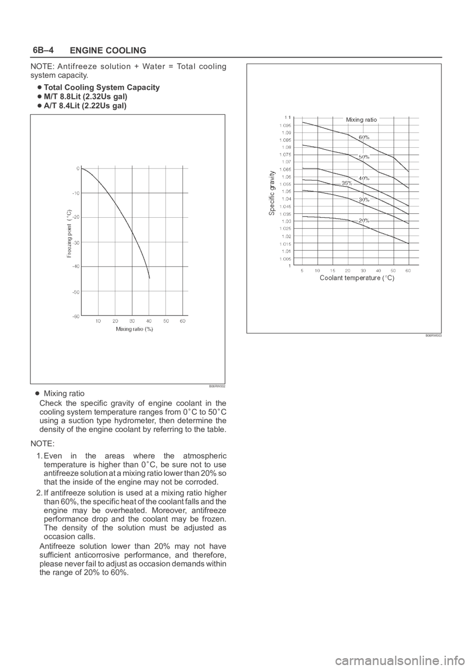
Mixing ratio
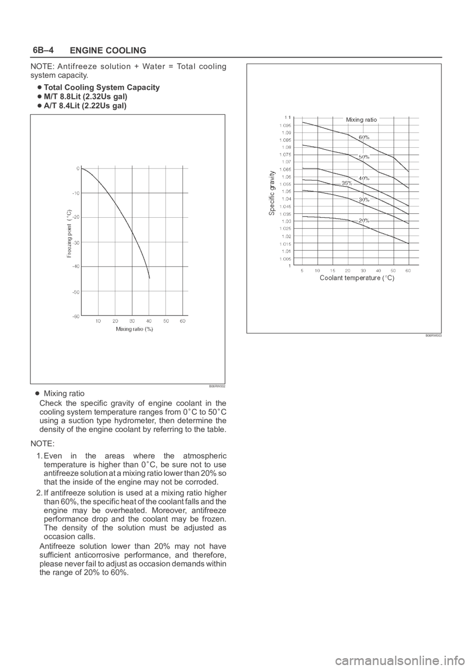
Check the specific gravity of engine coolant in the
cooling system temperature ranges from 0
C to 50C
using a suction type hydrometer, then determine the
density of the engine coolant by referring to the table.
NOTE:
1. Even in the areas where the atmospheric
temperature is higher than 0
C, be sure not to use
antifreeze solution at a mixing ratio lower than 20% so
that the inside of the engine may not be corroded.
2. If antifreeze solution is used at a mixing ratio higher
than 60%, the specific heat of the coolant falls and the
engine may be overheated. Moreover, antifreeze
performance drop and the coolant may be frozen.
The density of the solution must be adjusted as
occasion calls.
Antifreeze solution lower than 20% may not have
sufficient anticorrosive performance, and therefore,
please never fail to adjust as occasion demands within
the range of 20% to 60%.
B06RW003
Page 1066 of 6000
ENGINE COOLING6B–13
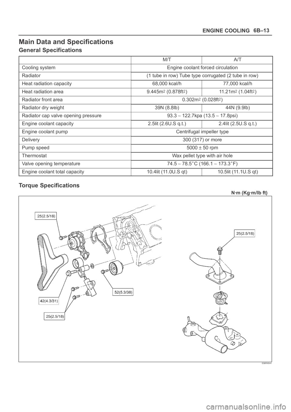
Main Data and Specifications
General Specifications
M/TA/T
Cooling systemEngine coolant forced circulation
Radiator(1 tube in row) Tube type corrugated (2 tube in row)
Heat radiation capacity68,000 kcal/h77,000 kcal/h
Heat radiation area9.445m (0.878ft)11 . 2 1 m (1.04ft)
Radiator front area0.302m (0.028ft)
Radiator dry weight39N (8.8lb)44N (9.9lb)
Radiator cap valve opening pressure93.3 122.7kpa (13.5 17.8psi)
Engine coolant capacity2.5lit (2.6U.S q.t.)2.4lit (2.5U.S q.t.)
Engine coolant pumpCentrifugal impeller type
Delivery300 (317) or more
Pump speed5000 50 rpm
ThermostatWax pellet type with air hole
Valve opening temperature74.5 78.5C (166.1 173.3F)
Engine coolant total capacity10.4lit (11.0U.S qt)10.5lit (11.1U.S qt)
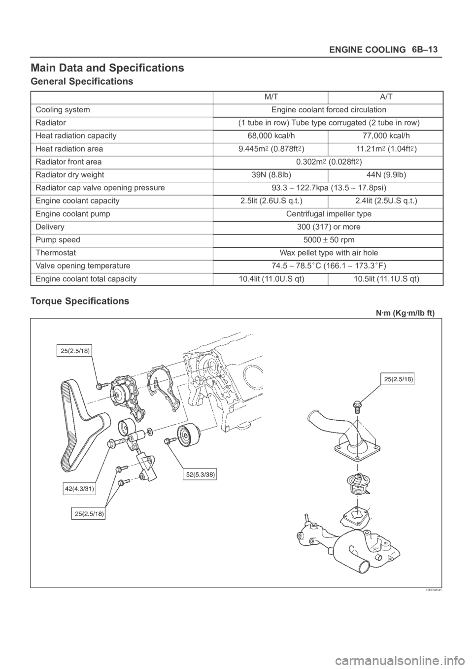
Torque Specifications
Nꞏm (Kgꞏm/lb ft)
E06RW041
Page 1736 of 6000

ENGINE MECHANICAL 6A – 3
SERVICE INFORMATION
MAIN DATA AND SPECIFICATION
Engine type Diesel, four cycle water cooled inline
Camshaft type DOHC
Number of cylinders 4
Bore x stroke (mm) 95.4 x 104.9
Total piston displacement (cc) 2999
Compression ratio (to 1) 19.0
For Europe : 18.5
Engine weight (dry) N (kg/lb) 2492 (254/560) (A/T)
For Europe : 2422 (247/545) (A/T)
2649 (270/593) (M/T)
For Europe : 2697 (275/606) (M/T)
Engine idling speed (Reference) RPM 720
Compression pressure kpa (kg/cm
2/psi)-rpm 3040 (31/441)-200
Firing order 1–3–4–2
VALVE SYSTEM
Intake valves open at: B.T.D.C. 3°
close at: A.B.D.C. 57.6°
Exhaust valves open at: B.B.D.C. 56.5°
close at: A.T.D.C. 5°
Valve clearance (at cold) mm (in)
intake: 0.15 (0.006)
exhaust: 0.25 (0.01)
Oil filter Full flow and bypass combined type
Oil capacity (Original factory fill or rebuilt engine) 9.0 liters (7.9 US quarts)
Oil capacity (Service change)
with filter change 6.0 liters (6.3 US quarts)
without filter change 5.0 liters (5.3 US quarts)
Oil cooler Water cooled type
Inter cooler Air cooled type
Turbocharger method
Control method Wastegate control
Lubrication Pressurized control
Cooling method Coolant cooled
Crankshaft
As tufftriding (Nitrizing treatment) is applied to increase
crankshaft strength, crankpins and journals should not
be reground.
Piston Cooling
An oiling jet device for piston cooling is provided in the
lubricating oil circuit from the cylinder block oil gallery
via a check valve.
Take care not to damage any oiling jet when removing
and installing piston and connecting assembly.
Fuel Injection System
The injection system is oil rail type.
Quick On Start 4 System
QOS4 preheating system which features a quick-on
glow plug with thermometer control of the glowing time
and the afterglow time function, is applied.
Page 1737 of 6000

6A – 4 ENGINE MECHANICAL
Engine Cooling
Starting System
Cooling system Coolant forced circulation
Radiator (2 tube in row) Tube type corrugated
Heat radiation capacity J/h (kcal/h) 318 x 10
6(76000)
Heat radiation area m
2(ft2) 15.63 (1.454)
Front area m
2(ft2) 0.309 (2.029)
Dry weight N (kg/lb) 83 (8.5/18.7)
Radiator cap
Valve opening pressure kPa (kg/cm
2/ psi) 93.3 – 122.7 (0.95 – 1.25/13.5 – 17.8)
Coolant capacity lit (Imp.qt./US qt.) M/T 2.5 (2.2/2.6) A/T 2.4 (2.1/2.5)
Coolant pump Centrifugal impeller type
Pulley ratio (to 1) 1.2
Coolant total capacity lit (Imp.qt./US qt.) 9.3 (8.2/9.8)
Model HITACHI S14-0
Rating
Vo l t a ge V 1 2
Output kW 2.8
Time sec 30
Number of teeth of pinion 9
Rotating direction (as viewed from pinion) Clockwise
Weight (approx.) N(kg/lb) 49 (5.0/11)
No-load characteristics
Voltage/current V/A 11/160 or less
Speed rpm 4000 or more
Load characteristics
Voltage/current V/A 8.76/300
Torque Nꞏm(kgꞏm/lbꞏft) 7.4 (0.75/5.4) or more
Speed rpm 1700 or more
Locking characteristics
Voltage/current V/A 2.5/1100 or less
Torque Nꞏm(kgꞏm/lbꞏft) 18.6 (1.9/14) or more
Page 1837 of 6000

6B – 4 ENGINE COOLING
ANTI-FREEZE SOLUTION
Relation between Mixing ratio and Freezing point
Freezing temperature of the engine coolant varies
with the ratio of anti-freeze solution in water.
Proper mixing ratio can be determined by refering
to the chart. Supplemental inhibitors or additives
claiming to increase cooling capability that have not
been specifically approved by Isuzu are not
recommended for addition to the cooling system.
Calculation of mixing ratio
Mixing ratio (%)
=Anti-freeze solution (Lit/qt.)
100
Anti-freeze solution (Lit/qt.) + Water (Lit/qt.)
For example
In case total coolant capacity = 10
It is necessary to mix about 35% anti-freeze
solution at ambient temperature minus 20°C.
Capacity of anti-freeze solution:
35
10 = 3.5 100
Water capacity: 10
– 3.5 = 6.5
Therefore, you prepare the water 6.5 and anti-
freeze solution 3.5
, then mix them to get total
10
coolant.
Mixing ratio
Check the specific gravity of engine coolant in the
cooling system in temperature ranges from 0° C to
50° C using a suction type hydrometer, then
determine the density of the coolant by referring to
the table at below.
-1010 0
Freezing Temperature(
C)
20 30 Antifreeze Solution Density(%)
40 50
-20
-30
-40
B06RW018
1,100
20 10 30 4060%
50%
40%
20%
10%
30%
Antifreeze Solution Temperature(
C) 50 60 70 0
Specific Gravity
1,090
1,080
1,070
1,060
1,050
1,040
1,030
1,020
1,010
1,000
B06RW017
Page 1839 of 6000
6B – 6 ENGINE COOLING
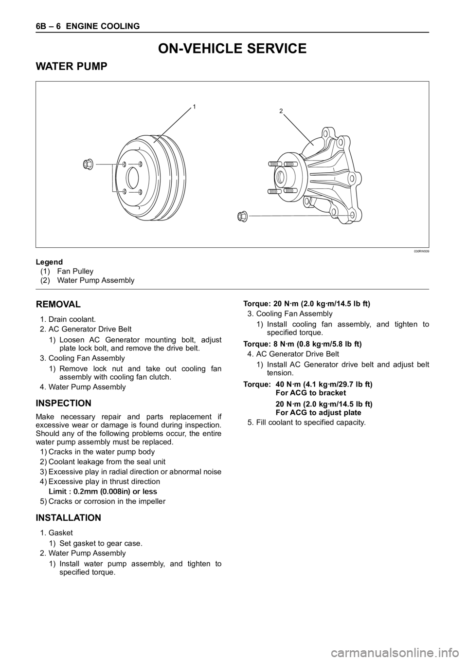
REMOVAL
1. Drain coolant.
2. AC Generator Drive Belt
1) Loosen AC Generator mounting bolt, adjust
plate lock bolt, and remove the drive belt.
3. Cooling Fan Assembly
1) Remove lock nut and take out cooling fan
assembly with cooling fan clutch.
4. Water Pump Assembly
INSPECTION
Make necessary repair and parts replacement if
excessive wear or damage is found during inspection.
Should any of the following problems occur, the entire
water pump assembly must be replaced.
1) Cracks in the water pump body
2) Coolant leakage from the seal unit
3) Excessive play in radial direction or abnormal noise
4) Excessive play in thrust direction
5) Cracks or corrosion in the impeller
INSTALLATION
1. Gasket
1) Set gasket to gear case.
2. Water Pump Assembly
1) Install water pump assembly, and tighten to
specified torque.Torque: 20 Nꞏm (2.0 kgꞏm/14.5 lb ft)
3. Cooling Fan Assembly
1) Install cooling fan assembly, and tighten to
specified torque.
Torque: 8 Nꞏm (0.8 kgꞏm/5.8 lb ft)
4. AC Generator Drive Belt
1) Install AC Generator drive belt and adjust belt
tension.
Torque: 40 Nꞏm (4.1 kgꞏm/29.7 lb ft)
For ACG to bracket
20 Nꞏm (2.0 kgꞏm/14.5 lb ft)
For ACG to adjust plate
5. Fill coolant to specified capacity.
12
Legend
(1) Fan Pulley
(2) Water Pump Assembly
030RW009
ON-VEHICLE SERVICE
WAT E R P U M P
Page 2134 of 6000
ENGINE LUBRICATION 6G – 3
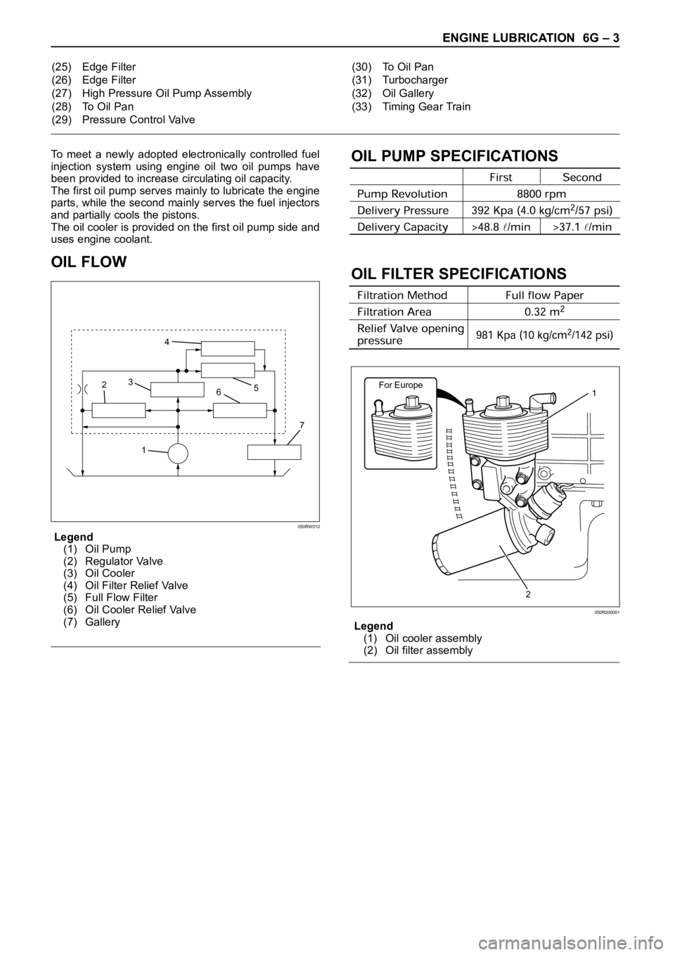
To meet a newly adopted electronically controlled fuel
injection system using engine oil two oil pumps have
been provided to increase circulating oil capacity.
The first oil pump serves mainly to lubricate the engine
parts, while the second mainly serves the fuel injectors
and partially cools the pistons.
The oil cooler is provided on the first oil pump side and
uses engine coolant.
OIL FLOW
Legend
(1) Oil Pump
(2) Regulator Valve
(3) Oil Cooler
(4) Oil Filter Relief Valve
(5) Full Flow Filter
(6) Oil Cooler Relief Valve
(7) Gallery
OIL PUMP SPECIFICATIONS
OIL FILTER SPECIFICATIONS
Legend
(1) Oil cooler assembly
(2) Oil filter assembly (25) Edge Filter
(26) Edge Filter
(27) High Pressure Oil Pump Assembly
(28) To Oil Pan
(29) Pressure Control Valve(30) To Oil Pan
(31) Turbocharger
(32) Oil Gallery
(33) Timing Gear Train
17 65 4
3
2
050RW010
For Europe1
2
050R200001
Page 4597 of 6000
6B–4
ENGINE COOLING
NOTE: Antifreeze solution + Water = Total cooling
system capacity.
Total Cooling System Capacity
M/T 8.8Lit (2.32Us gal)
A/T 8.4Lit (2.22Us gal)
B06RW002
Mixing ratio
Check the specific gravity of engine coolant in the
cooling system temperature ranges from 0
C to 50C
using a suction type hydrometer, then determine the
density of the engine coolant by referring to the table.
NOTE:
1. Even in the areas where the atmospheric
temperature is higher than 0
C, be sure not to use
antifreeze solution at a mixing ratio lower than 20% so
that the inside of the engine may not be corroded.
2. If antifreeze solution is used at a mixing ratio higher
than 60%, the specific heat of the coolant falls and the
engine may be overheated. Moreover, antifreeze
performance drop and the coolant may be frozen.
The density of the solution must be adjusted as
occasion calls.
Antifreeze solution lower than 20% may not have
sufficient anticorrosive performance, and therefore,
please never fail to adjust as occasion demands within
the range of 20% to 60%.
B06RW003
Page 4606 of 6000
ENGINE COOLING6B–13
Main Data and Specifications
General Specifications
M/TA/T
Cooling systemEngine coolant forced circulation
Radiator(1 tube in row) Tube type corrugated (2 tube in row)
Heat radiation capacity68,000 kcal/h77,000 kcal/h
Heat radiation area9.445m (0.878ft)11 . 2 1 m (1.04ft)
Radiator front area0.302m (0.028ft)
Radiator dry weight39N (8.8lb)44N (9.9lb)
Radiator cap valve opening pressure93.3 122.7kpa (13.5 17.8psi)
Engine coolant capacity2.5lit (2.6U.S q.t.)2.4lit (2.5U.S q.t.)
Engine coolant pumpCentrifugal impeller type
Delivery300 (317) or more
Pump speed5000 50 rpm
ThermostatWax pellet type with air hole
Valve opening temperature74.5 78.5C (166.1 173.3F)
Engine coolant total capacity10.4lit (11.0U.S qt)10.5lit (11.1U.S qt)
Torque Specifications
Nꞏm (Kgꞏm/lb ft)
E06RW041
Page 5276 of 6000

ENGINE MECHANICAL 6A – 3
SERVICE INFORMATION
MAIN DATA AND SPECIFICATION
Engine type Diesel, four cycle water cooled inline
Camshaft type DOHC
Number of cylinders 4
Bore x stroke (mm) 95.4 x 104.9
Total piston displacement (cc) 2999
Compression ratio (to 1) 19.0
Engine weight (dry) N (kg/lb) 2492 (254/560) (A/T)
2649 (270/593) (M/T)
Engine idling speed (Reference) RPM 720
Compression pressure kpa (kg/cm
2/psi)-rpm 3000 (31/440)-200
Firing order 1–3–4–2
VALVE SYSTEM
Intake valves open at: B.T.D.C. 3°
close at: A.B.D.C. 57.6°
Exhaust valves open at: B.B.D.C. 56.5°
close at: A.T.D.C. 5°
Valve clearance at cold mm (in)
intake: 0.15 (0.006)
exhaust: 0.25 (0.01)
Oil filter Full flow and bypass combined type
Oil capacity (Original factory fill or rebuilt engine) 9.0 liters (7.9 US quarts)
Oil capacity (Service change)
with filter change 6.0 liters (6.3 US quarts)
without filter change 5.0 liters (5.3 US quarts)
Oil cooler Water cooled type
Inter cooler Air cooled type
Turbocharger method
Control method Wastegate control
Lubrication Pressurized control
Cooling method Coolant cooled