wheel alignment OPEL FRONTERA 1998 Workshop Manual
[x] Cancel search | Manufacturer: OPEL, Model Year: 1998, Model line: FRONTERA, Model: OPEL FRONTERA 1998Pages: 6000, PDF Size: 97 MB
Page 439 of 6000

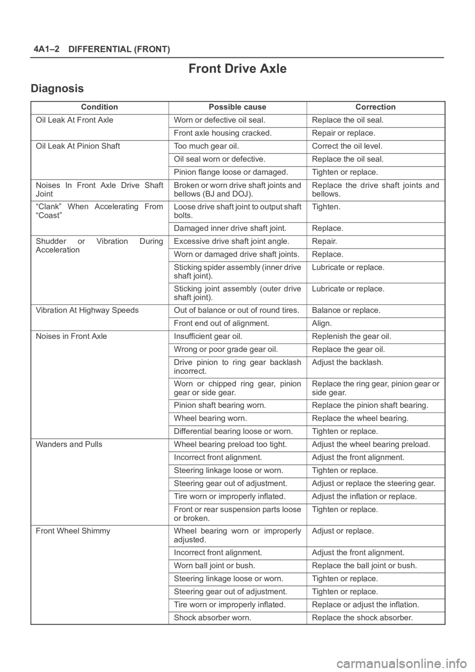
DIFFERENTIAL (FRONT) 4A1–2
Front Drive Axle
Diagnosis
ConditionPossible causeCorrection
Oil Leak At Front AxleWorn or defective oil seal.Replace the oil seal.
Front axle housing cracked.Repair or replace.
Oil Leak At Pinion ShaftToo much gear oil.Correct the oil level.
Oil seal worn or defective.Replace the oil seal.
Pinion flange loose or damaged.Tighten or replace.
Noises In Front Axle Drive Shaft
JointBroken or worn drive shaft joints and
bellows (BJ and DOJ).Replace the drive shaft joints and
bellows.
“Clank” When Accelerating From
“Coast”Loose drive shaft joint to output shaft
bolts.Tighten.
Damaged inner drive shaft joint.Replace.
Shudder or Vibration During
Acceleration
Excessive drive shaft joint angle.Repair.
AccelerationWorn or damaged drive shaft joints.Replace.
Sticking spider assembly (inner drive
shaft joint).Lubricate or replace.
Sticking joint assembly (outer drive
shaft joint).Lubricate or replace.
Vibration At Highway SpeedsOut of balance or out of round tires.Balance or replace.
Front end out of alignment.Align.
Noises in Front AxleInsufficient gear oil.Replenish the gear oil.
Wrong or poor grade gear oil.Replace the gear oil.
Drive pinion to ring gear backlash
incorrect.Adjust the backlash.
Worn or chipped ring gear, pinion
gear or side gear.Replace the ring gear, pinion gear or
side gear.
Pinion shaft bearing worn.Replace the pinion shaft bearing.
Wheel bearing worn.Replace the wheel bearing.
Differential bearing loose or worn.Tighten or replace.
Wanders and PullsWheel bearing preload too tight.Adjust the wheel bearing preload.
Incorrect front alignment.Adjust the front alignment.
Steering linkage loose or worn.Tighten or replace.
Steering gear out of adjustment.Adjust or replace the steering gear.
Tire worn or improperly inflated.Adjust the inflation or replace.
Front or rear suspension parts loose
or broken.Tighten or replace.
Front Wheel ShimmyWheel bearing worn or improperly
adjusted.Adjust or replace.
Incorrect front alignment.Adjust the front alignment.
Worn ball joint or bush.Replace the ball joint or bush.
Steering linkage loose or worn.Tighten or replace.
Steering gear out of adjustment.Tighten or replace.
Tire worn or improperly inflated.Replace or adjust the inflation.
Shock absorber worn.Replace the shock absorber.
Page 669 of 6000

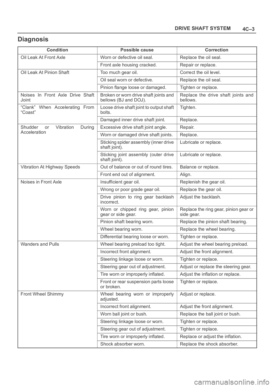
4C–3 DRIVE SHAFT SYSTEM
Diagnosis
ConditionPossible causeCorrection
Oil Leak At Front AxleWorn or defective oil seal.Replace the oil seal.
Front axle housing cracked.Repair or replace.
Oil Leak At Pinion ShaftToo much gear oil.Correct the oil level.
Oil seal worn or defective.Replace the oil seal.
Pinion flange loose or damaged.Tighten or replace.
Noises In Front Axle Drive Shaft
JointBroken or worn drive shaft joints and
bellows (BJ and DOJ).Replace the drive shaft joints and
bellows.
“Clank” When Accelerating From
“Coast”Loose drive shaft joint to output shaft
bolts.Tighten.
Damaged inner drive shaft joint.Replace.
Shudder or Vibration During
Acceleration
Excessive drive shaft joint angle.Repair.
AccelerationWorn or damaged drive shaft joints.Replace.
Sticking spider assembly (inner drive
shaft joint).Lubricate or replace.
Sticking joint assembly (outer drive
shaft joint).Lubricate or replace.
Vibration At Highway SpeedsOut of balance or out of round tires.Balance or replace.
Front end out of alignment.Align.
Noises in Front AxleInsufficient gear oil.Replenish the gear oil.
Wrong or poor grade gear oil.Replace the gear oil.
Drive pinion to ring gear backlash
incorrect.Adjust the backlash.
Worn or chipped ring gear, pinion
gear or side gear.Replace the ring gear, pinion gear or
side gear.
Pinion shaft bearing worn.Replace the pinion shaft bearing.
Wheel bearing worn.Replace the wheel bearing.
Differential bearing loose or worn.Tighten or replace.
Wanders and PullsWheel bearing preload too tight.Adjust the wheel bearing preload.
Incorrect front alignment.Adjust the front alignment.
Steering linkage loose or worn.Tighten or replace.
Steering gear out of adjustment.Adjust or replace the steering gear.
Tire worn or improperly inflated.Adjust the inflation or replace.
Front or rear suspension parts loose
or broken.Tighten or replace.
Front Wheel ShimmyWheel bearing worn or improperly
adjusted.Adjust or replace.
Incorrect front alignment.Adjust the front alignment.
Worn ball joint or bush.Replace the ball joint or bush.
Steering linkage loose or worn.Tighten or replace.
Steering gear out of adjustment.Tighten or replace.
Tire worn or improperly inflated.Replace or adjust the inflation.
Shock absorber worn.Replace the shock absorber.
Page 679 of 6000

4C–13 DRIVE SHAFT SYSTEM
9. Install lock washer and lock screw in the following
manner.
Turn the side with larger diameter of the tapered
bore to the vehicle outer side, then attach the
washer.
If the bolt holes in the lock plate are not aligned with
the corresponding holes in the nut, reverse the lock
plate.
If the bolt holes are still out of alignment, turn in the
nut just enough to obtain alignment.
Screw is to be fastened tightly so its head may
come lower than the surface of the washer.
411RS012
10. Apply adhesive (LOCTITE 515 or equivalent) to both
joining flange faces then install hub flange.
11. Install snap ring and shim.
Adjust the clearance between the free wheeling hub
body and the snap ring.
Clearance: 0 mm–0.3 mm (0 in–0.012 in)
Shims Available: 0.2 mm, 0.3 mm, 0.5 mm,
1.0 mm (0.008 in, 0.012 in, 0.020 in, 0.039 in)
411RW002
12. Install hub cap.
13. Tighten the bolts to the specified torque.
Torque: 59 Nꞏm (6.0 kgꞏm/43 lb ft)
Page 685 of 6000

4C–19 DRIVE SHAFT SYSTEM
21. Install lock washer and lock screw in the following
manner.
Turn the side with larger diameter of the tapered
bore to the vehicle outer side, and attach the
washer.
If the bolt holes in the lock plate are not aligned with
the corresponding holes in the nut, reverse the lock
plate.
If the bolt holes are still out of alignment, trun in the
nut just enough to obtain alignment.
Screw is to be fastened tightly so its head may
come lower than the surface of the washer.
411RS012
22. Install body assembly.
Apply adhesive (LOCTITE 515 or equivalent) to
both joining faces.
Tighten the bolts to the specified torque.
Torque:59Nꞏm (6.0kgꞏm/43lbft)
23. Install snap ring and shim.
Adjust the clearance between the free wheeling hub
body and the snap ring.
Clearance:
0-0.3mm (0-0.012in)
Shims Available:
0.2mm, 0.3mm, 0.5mm, 1.0mm, (0.008in, 0.012in,
0.020in, 0.039in)
411RW002
24. Install cover assembly.
Align stopper nails (1) to grooves of body (2).
411RW019
25. Tighten the cover bolts to the specified torque.
Torque:12Nꞏm (1.2kgꞏm/104lbin)
Page 1004 of 6000

6A–48
ENGINE MECHANICAL
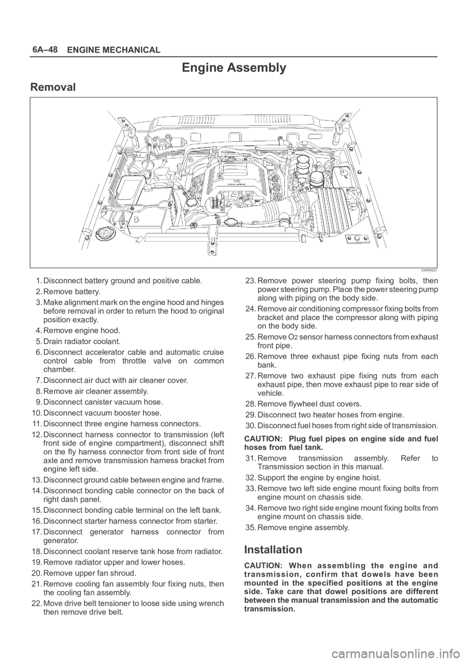
Engine Assembly
Removal
035RW027
1. Disconnect battery ground and positive cable.
2. Remove battery.
3. Make alignment mark on the engine hood and hinges
before removal in order to return the hood to original
position exactly.
4. Remove engine hood.
5. Drain radiator coolant.
6. Disconnect accelerator cable and automatic cruise
control cable from throttle valve on common
chamber.
7. Disconnect air duct with air cleaner cover.
8. Remove air cleaner assembly.
9. Disconnect canister vacuum hose.
10. Disconnect vacuum booster hose.
11. Disconnect three engine harness connectors.
12. Disconnect harness connector to transmission (left
front side of engine compartment), disconnect shift
on the fly harness connector from front side of front
axle and remove transmission harness bracket from
engine left side.
13. Disconnect ground cable between engine and frame.
14. Disconnect bonding cable connector on the back of
right dash panel.
15. Disconnect bonding cable terminal on the left bank.
16. Disconnect starter harness connector from starter.
17. Disconnect generator harness connector from
generator.
18. Disconnect coolant reserve tank hose from radiator.
19. Remove radiator upper and lower hoses.
20. Remove upper fan shroud.
21. Remove cooling fan assembly four fixing nuts, then
the cooling fan assembly.
22. Move drive belt tensioner to loose side using wrench
then remove drive belt.23. Remove power steering pump fixing bolts, then
power steering pump. Place the power steering pump
along with piping on the body side.
24. Remove air conditioning compressor fixing bolts from
bracket and place the compressor along with piping
on the body side.
25. Remove O
2 sensor harness connectors from exhaust
front pipe.
26. Remove three exhaust pipe fixing nuts from each
bank.
27. Remove two exhaust pipe fixing nuts from each
exhaust pipe, then move exhaust pipe to rear side of
vehicle.
28. Remove flywheel dust covers.
29. Disconnect two heater hoses from engine.
30. Disconnect fuel hoses from right side of transmission.
CAUTION: Plug fuel pipes on engine side and fuel
hoses from fuel tank.
31. Remove transmission assembly. Refer to
Transmission section in this manual.
32. Support the engine by engine hoist.
33. Remove two left side engine mount fixing bolts from
engine mount on chassis side.
34. Remove two right side engine mount fixing bolts from
engine mount on chassis side.
35. Remove engine assembly.
Installation
CAUTION: W h e n a s s e m b l i n g t h e e n g i n e a n d
transmission, confirm that dowels have been
mounted in the specified positions at the engine
side. Take care that dowel positions are different
between the manual transmission and the automatic
transmission.
Page 2291 of 6000

7A1–46
TRANSMISSION CONTROL SYSTEM (4L30–E)
DTC P0722 Transmission Output Speed Sensor (OSS) Low Input
StepActionYe sNo
11. Install the scan tool.
2. With the engine “off”, turn the ignition switch “on”.
NOTE: Before clearing DTC(s), use the scan tool to record “Failure
Records” for reference, as data will be lost when the “Clear Info”
function is used.
3. Record the DTC “Failure Records”.
4. Raise the drive wheels.
5. Start the engine.
6. Place the transmission in any drive range.
With the drive wheels rotating, does the “Trans Output Speed”
increase with the drive wheel speed?
Go to Diagnostic
Aids
Go to Step 2
2Does the speedometer work?Go to Step 3Go to Step 4
3Check for the most current and/or incorrect calibration.
Is the calibration current?
Go to Step 16Go to Step 4
41. Turn the ignition “off”.
2. Disconnect the J3 (BLUE) PCM connector.
3. Using the J39200 DVOM, measure the resistance between
harness connector terminals J3–E1 and J3–E2.
Is the reading 3,000 ohms?
Go to Step 5Go to Step 6
51. Select AC volts.
2. Rotate the rear wheels, ensuring the driveshaft is turning.
Is the voltage greater than 0.5 volts?
Go to Step 7Go to Step 8
6Inspect circuits RED and WHT for a poor connection or an open
circuit.
Was a problem found?
Go to Step 17Go to Step 8
71. Reconnect the J3 (BLUE) PCM connector.
2. Disconnect the OSS harness from the OSS.
3. With the engine “off”, turn the ignition “on”.
4. Using the J 39200 DVOM, measure the voltage at the OSS
harness connector terminals M15–1 and M15–2.
Is the reading between 4.0 to 5.1 volts?
Go to Step 16Go to Step 10
81. Remove the OSS.
2. Check the output shaft speed sensor rotor for damage or
misalignment. Refer to Speed Sensor (Extension Housing) in
Automatic Transmission (4L30–E) section.
Was a problem found?
Go to Step 17Go to Step 9
9Replace the OSS.
Is the replacement complete?
Go to Step 17—
10Was the reading in step 8 less than 4.0 volts?Go to Step 12Go to Step 11
11Was the reading in Step 8 greater than 5.1 volts?Go to Step 15—
12Using the J 39200 DVOM to chassis ground, measure the voltage
on circuit RED.
Is the reading between 4.0 to 5.1 volts?
Go to Step 13Go to Step 14
13Repair the open in circuit WHT.
Is the repair complete?
Go to Step 17—
14Check circuit RED for a short to ground or open.
Was a problem found and corrected?
Go to Step 17Go to Step 16
Page 2294 of 6000

TRANSMISSION CONTROL SYSTEM (4L30–E)7A1–49
DTC P0723 Transmission Output Speed Sensor (OSS) Intermittent
StepActionYe sNo
11. Install the scan tool.
2. With the engine “off”, turn the ignition switch “on”.
NOTE: Before clearing DTC(s), use the scan tool to record “Failure
Records” for reference, as data will be lost when the “Clear Info”
function is used.
3. Record the DTC “Failure Records”.
4. Raise the drive wheels.
5. Start the engine.
6. Place the transmission in any drive range.
With the drive wheels rotating, does the “Trans Output Speed”
increase with the drive wheel speed?
Go to Diagnostic
Aids
Go to Step 2
2Does the speedometer work?Go to Step 3Go to Step 4
3Check for the most current and/or incorrect calibration.
Is the calibration current?
Go to Step 16Go to Step 4
41. Turn the ignition “off”.
2. Disconnect the J3 (BLUE) PCM connector.
3. Using the J39200 DVOM, measure the resistance between
harness connector terminals J3–E1 and J3–E2.
Is the reading 3,000 ohms?
Go to Step 5Go to Step 6
51. Select AC volts.
2. Rotate the rear wheels, ensuring the driveshaft is turning.
Is the voltage greater than 0.5 volts?
Go to Step 7Go to Step 8
6Inspect circuits RED and WHT for a poor connection or an open
circuit.
Was a problem found?
Go to Step 17Go to Step 8
71. Reconnect the J3 (BLUE) PCM connector.
2. Disconnect the OSS harness from the OSS.
3. With the engine “off”, turn the ignition “on”.
4. Using the J 39200 DVOM, measure the voltage at the OSS
harness connector terminals M15–1 and M15–2.
Is the reading between 4.0 to 5.1 volts?
Go to Step 16Go to Step 10
81. Remove the OSS.
2. Check the output shaft speed sensor rotor for damage or
misalignment. Refer to Speed Sensor (Extension Housing) in
Automatic Transmission (4L30–E) section.
Was a problem found?
Go to Step 17Go to Step 9
9Replace the OSS.
Is the replacement complete?
Go to Step 17—
10Was the reading in step 8 less than 4.0 volts?Go to Step 12Go to Step 11
11Was the reading in Step 8 greater than 5.1 volts?Go to Step 15—
12Using the J 39200 DVOM to chassis ground, measure the voltage
on circuit RED.
Is the reading between 4.0 to 5.1 volts?
Go to Step 13Go to Step 14
13Repair the open in circuit WHT.
Is the repair complete?
Go to Step 17—
14Check circuit RED for a short to ground or open.
Was a problem found and corrected?
Go to Step 17Go to Step 16
Page 2518 of 6000

CLUTCH7C–9
Clutch Assembly
Clutch Assembly and Associated Parts
201RW029
Legend
(1) Flywheel Assembly and Crankshaft Bearing
(2) Driven Plate Assembly (6VE1)
(3) Driven Plate Assembly (4JX1)
(4) Pressure Plate Assembly (5) Transmission Assembly
(6) Front Cover
(7) Shift Fork
(8) Release Bearing
Removal
1. Remove transmission assembly, refer to ”MANUAL
TRANSMISSION” of Section 7B for ”Removal AND
INSTALLATION” procedure.
2. Mark the flywheel, clutch cover and pressure plate lug
for alignment when installing.
3. Remove pressure plate assembly (3).
4. Remove driven plate assembly (1) or (2). Use the pilot
aligner 5-85253-001-0 (J-24547) to prevent the
driven plate assembly from falling free.
201RW031
Page 2519 of 6000

7C–10CLUTCH
5. Mark the flywheel, clutch cover and pressure plate lug
for alignment when installing.
6. Remove the release bearing (3) from the
transmission case .
7. Remove the shift fork snap pin.
8. Remove the shift fork pin and shift fork (4) from the
front cover.
9. Remove the front cover bolts.
10. Remove the front cover (5) from the transmission
case.
220RW088
11. Remove flywheel assembly and crankshaft bearing.
Do not remove except for replacement.
12. Use the remover 5–8840–2000–0 (J–5822) and
sliding hammer 5–8840–0019–0 (J–23907) to
remove the crankshaft bearing
015RW053
Inspection and Repair
Make necessary correction or parts replacement if wear,
damage, or any other abnormal condition are found
through inspection.
Pressure Plate Assembly
201RS002
1. Visually check the pressure plate friction surface for
excessive wear and heat cracks.
2. If excessive wear or deep heat cracks are present,
the pressure plate must be replaced.
Pressure Plate Warpage
201RS003
Page 2557 of 6000

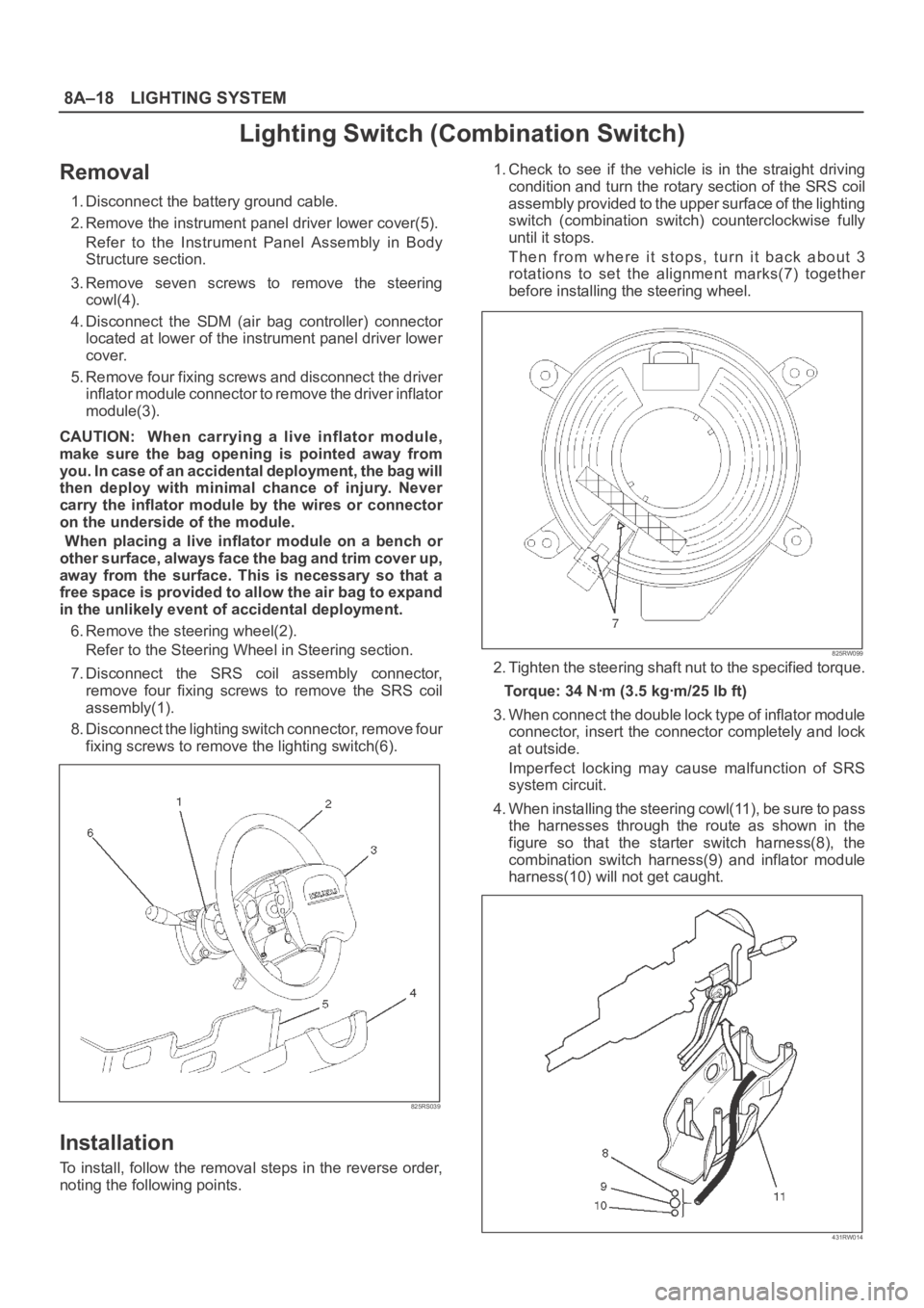
8A–18LIGHTING SYSTEM
Lighting Switch (Combination Switch)
Removal
1. Disconnect the battery ground cable.
2. Remove the instrument panel driver lower cover(5).
Refer to the Instrument Panel Assembly in Body
Structure section.
3. Remove seven screws to remove the steering
cowl(4).
4. Disconnect the SDM (air bag controller) connector
located at lower of the instrument panel driver lower
cover.
5. Remove four fixing screws and disconnect the driver
inflator module connector to remove the driver inflator
module(3).
CAUTION: When carrying a live inflator module,
make sure the bag opening is pointed away from
y o u . I n c a s e o f a n a c c i d e n t a l d e p l o y m e n t , t h e b a g w i l l
then deploy with minimal chance of injury. Never
carry the inflator module by the wires or connector
on the underside of the module.
When placing a live inflator module on a bench or
other surface, always face the bag and trim cover up,
away from the surface. This is necessary so that a
free space is provided to allow the air bag to expand
in the unlikely event of accidental deployment.
6. Remove the steering wheel(2).
Refer to the Steering Wheel in Steering section.
7. Disconnect the SRS coil assembly connector,
remove four fixing screws to remove the SRS coil
assembly(1).
8. Disconnect the lighting switch connector, remove four
fixing screws to remove the lighting switch(6).
825RS039
Installation
To install, follow the removal steps in the reverse order,
noting the following points.1. Check to see if the vehicle is in the straight driving
condition and turn the rotary section of the SRS coil
assembly provided to the upper surface of the lighting
switch (combination switch) counterclockwise fully
until it stops.
Then from where it stops, turn it back about 3
rotations to set the alignment marks(7) together
before installing the steering wheel.
825RW099
2. Tighten the steering shaft nut to the specified torque.
Torque: 34 Nꞏm (3.5 kgꞏm/25 lb ft)
3. When connect the double lock type of inflator module
connector, insert the connector completely and lock
at outside.
Imperfect locking may cause malfunction of SRS
system circuit.
4. When installing the steering cowl(11), be sure to pass
the harnesses through the route as shown in the
figure so that the starter switch harness(8), the
combination switch harness(9) and inflator module
harness(10) will not get caught.
431RW014