engine OPEL GT-R 1973 User Guide
[x] Cancel search | Manufacturer: OPEL, Model Year: 1973, Model line: GT-R, Model: OPEL GT-R 1973Pages: 625, PDF Size: 17.22 MB
Page 20 of 625
LUBRICATION AND MAINTENANCE OC-11
Throttle Linkage
Check for damaged or missing parts, interference or
binding. Any deficiencies should be corrected with-
out delay.
Headlights
Check for proper aim. Correct as necessary. More
frequent checks should be made if oncoming motor-
ists signal when you are already using your low
beams, or if illumination of the area ‘ahead seems
inadequate.
Underbody
In geographic areas using a heavy concentration of
road salt or other corrosive materials for snow re-
moval or road dust control, flush and inspect the
complete under side of the car at least once each
year, preferably after a winter’s exposure. Particular
attention should be given to cleaning out underbody
members where dirt and other foreign materials may
have collected.
EMISSION CONTROL MAINTENANCE
Thermostatically Controlled Air Cleaner
Inspect installation to make certain that all hoses and
ducts are connected and correctly installed. Also,
check valve for proper operation.
Carburetor Choke
Check choke mechanism for free operation. A bind-
ing condition may have developed from petroleum
gum formation on the choke shaft or from overtight-
ening of air cleaner clamp. Also check electric choke
terminal connections and fuse.
Timing, Dwell and Distributor
Adjust timing and dwell accurately as outlined under
Tune-Up in Group 6 at the first 4 months or 6,ooOmiles of operation, then at 12 month or
12,OQO mile
intervals. Adjustments must be made with test equip-
ment known to be accurate.
Replace distributor points every 12 months or 12,000
miles and carefully clean and inspect the complete
distributor cap to prevent misfiring and deteriora-
tion.
Carburetor and Idle
SpeedTorque carburetor attaching bolts and/or nuts to 12
ft.lbs. to compensate for compression of gasket atiirst 4 months or 6,000 miles of vehicle operation.Adjust idle speed to specifications with known accu-
rate equipment.
Proper functioning of the carburetor is particularly
essential to control of emissions. Correct mixtures
for emission compliance and idle quality have been
preset by Opel. Plastic idle mixture limiters have
been installed on the idle mixture screw, idle air
screw, and throttle stop screw to preclude unauthor-
ized adjustment. The plastic caps on the idle mixture
screw and the idle adjustment screw must be
removed to perform an idle speed adjustment. The
plastic cap on the throttle stop screw is not to be
removed unless some major carburetor repair or re-
placement which affects the throttle stop screw ad-
justment has been necessary.
Carburetor Fuel Inlet Filter
Replace filter at 12 month or
12,OCO mile intervals
or more often if clogged.
Spark Plugs
Replace at
6,ooO mile intervals when operating with
leaded fuels or at 12,000 mile intervals when using
unleaded fuels. Use of leaded fuels results in lead
deposits on spark plugs and can cause misfiring at
mileages less than
12,OilO miles. Where misfiring oc-
curs prior to
6,ooO miles, spark plugs in good condi-
tion can often be cleaned, tested and reinstalled in an
engine with acceptable results.
Spark Plug Wires
Inspect spark plug wires for evidence of checking or
cracking of exterior insulation and tight fit in the
distributor cap and at the spark plugs. Exterior of
wires should be cleaned, any evidence of corrosion
on ends removed and wire replace if deteriorated.
Positive Crankcase Ventilation System
The PCV metered orifice should be cleaned at 12,000
mile intervals under normal use, and at 6,000 mile
intervals when the vehicle is used under the follow-
ing conditions: driving in dusty conditions, extensive
idling, trailer pulling and short trip operation at
freezing temperatures (engine not thoroughly
warmed-up).
Evaporation Control System
Check all fuel and vapor lines and hoses for proper
connections and correct routing as well as condition.
Remove canister and check for cracks or damage.
Replace damaged or deteriorated parts as necessary.
Replace filter in open end of canister at 24month/24,000 mile intervals.
Page 21 of 625
!
OC-12 1973 OPEL SERVICE MANUAL iExhaust Gas Recirculation Systep
Check system operation at 12 &onth/12,000 mile
intervals. Clean valve and EGR &usages if required;
A valve with a damaged diaphragm must be re-
placed.I
Engine CompressionTest engine cranking compressi& If a problem
exists, correct it Minimum compression recorded;
many one cylinder should not be less that 70% ‘of
highest cylinder. For example, if fhe highest presstire
in any one cylinder is 150 pounds, the lowest
alloka-ble pressure for any other cylinder would be
l-05pounds (150
x 70% = 105).~
Fuel Cap, Fuel Lines and Fuel TankInspect the fuel tank, cap and lines for damage which
could cause leakage. Inspect fuel cap for correct seal-
ing ability and indications of physical damage. Re-
place any damaged or malfunctionining parts.
Air Cleaner ElementReplace the engine air cleaner element under normal
operating conditions every 24,000 miles. Operation
of vehicle in dusty areas will necessitate more fre-
quent element replacement.
CAUTION: Do not operate the engine with-
out the air cleaner unless temporary re-
moval is necessary during repair or
maintenance of the vehicle. When the aircIeaner is removed, backfiring can cause
fire in the engine compartment.
Page 24 of 625
BATTERY AND CABLES - ALL MODELSlA- 3
lost as the result of charging and discharging, and it
must be replaced before the electrolyte level falls to
the tops:of the separators. If the water is not replacedand the plates become exposed, they may become
permanently sulphated, which would impair the
per-forma”& of the plates. Also, the plates cannot take
full
par! in the battery action unless they are com-
pletely covered by the electrolyte.
Importance of Keeping Battery Properly Charged
The battery has three major functions: (1) It provides
a source of energy for cranking the engine. (2) It actsas a stabilizer to the voltage in the electrical system.
(3) It
c+n for a limited time furnish energy when the
demand: of the electrical units in operation exceed
the output of the generator.
In
ordei for the battery to continue to function, it is
necessaiy that current withdrawal from the battery
be balanced by current input from the generator so
that the battery is maintained in a properly chargedconditidn. If the outgo exceeds the input, the battery
will be&me discharged so that it cannot.supply suffi-cient energy.
The state of charge of the battery as well as the
temperature of the electrolyte has an important bear-ing on its capacity for supplying energy. Battery effi-
ciency is greatly reduced by decreased electrolyte
temper&e as it has a decided numbing effect on its
electrodhemical action. Under high discharge such
as cranking, battery voltage drops to lower values incold temperatures than in warm temperatures.
In
extrkmely cold climates it is important to keepbatter& in a nearly full charged condition to avoid
the possibility of freezing, which will damage any
battery!
The following table shows the temperatures at whichfreezing will occur in electrolytes of
differennt densi-
ties, wifh specific gravity corrected to 80 degrees l?
Specific Gravity Freezing Point
1.220 -35 degrees F.
1.200
-35 degrees F.
1.160
d degrees F.
Care of Dry Batteries in StorageA “dry charge” battery contains fully charged posi-
tive
a$ negative plates but no electrolyte.
Dry charged batteries should be stored in a dry placeaway from excessive heat. A dry charged battery
should
p kept in its original carton until ready to beput into service. This type of battery will retain its
“charged” condition indefinitely if protected from
moisture. Dry batteries may be stacked in vertical
columns provided they are not stacked more than
four high.
Preparing Dry Charged Batteries For ServiceTo prepare “dry charge” batteries for service use
approved battery-grade acid electrolyte (1.265 sp. gr.
at 80 degrees F). Care should be exercised in its useto prevent bodily injury or damage to clothing or
other material resulting from actual contact with the
electrolyte.
Electrolyte should be added to dry charged batteriesin an area where water is readily available for flush-
ing in case the electrolyte comes into contact with the
body. Refer to instructions on side of electrolyte con-tainer for antidotes to use if electrolyte comes into
contact with the body.
It is strongly recommended that a person filling bat-
teries with electrolyte wear glasses (preferably safetyglasses) to prevent possible damage to the eyes
should any spattering of the electrolyte occur.
1, Remove dry charged battery from its original car-
ton.2. Remove the vent plugs.
3. Using a glass or acid-proof plastic funnel, till eachbattery cell with electrolyte. Do not use a metal
funnel for filling the battery. The cell is properlytilled when the electrolyte level rises to the split ring
at the bottom of the vent well. Do not overfill orundertill. Overfilling will cause acid corrosion in the
,battery area; undertilling will cause early battery fail-
UR.4. After tilling cells, wait five to ten minutes and add
additional electrolyte, if necessary, to bring the elec-
trolyte to the proper level.
5. Never finish tilling a dry charge battery with wa-
ter. If electrolyte is spilled, more electrolyte must be
obtained.
Test After Batteries
ere Prepared For ServiceThe Delco Dry Charge Battery may be put into ser-
vice immediately after activation. However, to insuregood battery performance, the following activation
tests are recommended:1. After adding electrolyte,, check the open circuit
voltage. Less than 10 volts mdicates a reverse cell oran open circuit and the battery should be replaced.
2. Check the specific gravity of all cells. If the specific
Page 25 of 625
1A. 4 1973 OPEL SERVICE MANUAL
gravity corrected to 80 degrees F.’ shows more than
a thirty point
(.030) drop from the initial tilling with
electrolyte, or if one or more cells’gas violently after
addition of electrolyte, the batteiy should be fulty
charged before use.
3. For best performance in cold weather (32 degrees
F. or less), or if the battery and the electrolyte are not
at 60 degrees F., or above at time of activation, warm
the battery by boost charging.
TROUBLE DIAGNOSIS
BATTERY AND CABLES. TRDUBLE DIAGNOSIS
Quick Check of Battery and Cables
Whenever electrical trouble developes, it is desirable
to make a quick check of the battery and cables to
make certain that this source of current is in good
condition, securely connected, and is functioning
properly. This check will also give a good check on
the cranking system.
1. Turn on the lights. They should’burn steadily and
with normal brilliance.
2. With lights burnings, operate the cranking motor.
Either have the headlights shining on a wall so their
brilliance can be noted, or have someone watching
the headlights.
3. When cranking motor solenoid switch is
closeh,one of the following conditions will occur; (1) Lights
will stay bright or will dim slightly if temperature is
cold, and engine will be cranked at normal speed; (P
Lights will
gb out; (3) Lights will dim considerably;
(4) Lights will stay bright but no cranking action will
take place. The first named condition indicates that
nothing is wrong with the battery, cables, and crank-
ing system. The other conditions indicate trouble
aSfollows:
4. If fightsgo
out as cranking motor solenoid switch
is closed, it indicates a poor connection in the circuit
between battery and cranking motor. Check battery
cables and clean and tighten loose or corroded termi-
nals.
5. If
lights dim considerably as cranking motor
solenoid switch is closed, it indicates that the battery
is run down, or there is a condition in cranking
mb-tor or engine which causes an excessive current drain
on the battery. A low battery will be indicated by ,a
clattering noise in cranking motor solenoid because
the battery cannot sustain the voltage required to
hold solenoid plunger “in” after switch contacts
close and the “pull in” winding is shorted out.
Test battery with a 421 Battery Test. If battery is
found to be in good condition check cranking motor.
6.Iflights stay bright but no cranking action occurswhen cranking motor solenoid switch is closed, it
indicates an open circuit in cranking motor, switch,
or control circuit.
Testing Resistance of Cables and Terminal
Connections
Battery cables and terminal connections may be
tested with equipment comprising of a voltmeter (5
volts maximum), ammeter of 300 or more amperes
capacity, and carbonpile rheostat having a minimum
capacity of 300 amperes connected in series with the
ammeter.
I. Adjust rheostat to provide maximum resistance
(“OFF” position).
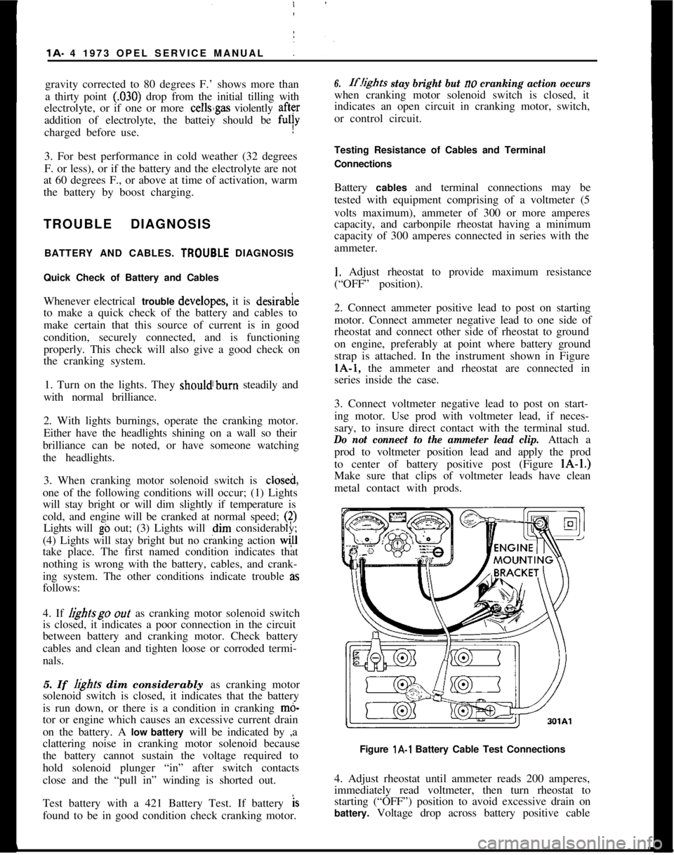
2. Connect ammeter positive lead to post on starting
motor. Connect ammeter negative lead to one side of
rheostat and connect other side of rheostat to ground
on engine, preferably at point where battery ground
strap is attached. In the instrument shown in FigurelA-1, the ammeter and rheostat are connected in
series inside the case.
3. Connect voltmeter negative lead to post on start-
ing motor. Use prod with voltmeter lead, if neces-
sary, to insure direct contact with the terminal stud.
Do not connect to the ammeter lead clip.Attach a
prod to voltmeter position lead and apply the prod
to center of battery positive post (Figure lA-1.)
Make sure that clips of voltmeter leads have clean
metal contact with prods.
Figure l A-l Battery Cable Test Connections
4. Adjust rheostat until ammeter reads 200 amperes,
immediately read voltmeter, then turn rheostat to
starting (“OFF”) position to avoid excessive drain on
battery. Voltage drop across battery positive cable
Page 26 of 625
BATTERY AND CABLES - ALL MODELSlA- 5
and terminal connections should not exceed 2/10
volt.
5. Connedt voltmeter positive lead to ground on en-
gine.
At&h prod to voltmeter negative lead and
apply prod to center of battery negative post. Volt-
age drop across the battery ground cable and termi-
nal conne$tions should not exceed 2/10 volt at
200amps.
6. A reading in excess of 2/10 volt when testing
either battery cable indicates excessive resistance in
cable or cpnnections. Clean and tighten cable or con-
nections. Clean and tighten cable terminals
(sub-para. c, below) and recheck for voltage drop. If volt-
age drop Still exceeds 2/10 volt, replace cable with a
genuine Buick-Opel cable to insure ample capacity.
Undercharge Failure of BatteryThe most frequent trouble experienced with storage
batteries is failure to maintain a state of charge suffi-
cient to crank the engine and also furnish current to
the ignitibn system, lights and accessories. Failure to
maintain a proper state of charge may be due to one
or more of the following conditions:
1.
Opertiting Conditions. When determining cause
of premature failure of a battery, consideration must
be given /to the conditions under which the car is
operated.,
In very low temperatures the capacity of a storage
battery
ii considerably reduced and the energy re-
quired f& cranking the. engine is considerably in-
creased. :
Frequent starting, particularly in cold weather,
ac-compani
place in the limited running time. This condition is
aggravated by night driving when lights are turned
on, or by operation of an air conditioner in heavy
traffic.
When thk car is operated under these conditions,adjusting,the voltage regulator to the high limit may
allow enough increase to keep the battery at a safe
state of charge. If the high limit setting does not
maintain a safe state of charge, an occasional booster
charge should be given to the battery.
2. Low charging Rate. In case of premature battery
failure, tbe charging rate of alternator should always
be checked and adjusted if below specifications.
3.
Zntemd Condition The internal condition of the
battery niay be such that it cannot hold a chargesatisfactoiily. Check electrolyte level and test the
battery using the 421 Battery Test.
Overcharge Failure of BatteryA common cause of battery failure is overcharging,
that is, continued input of excessive charging current
after the battery has reached a fully charged condi-
tion.
One evidence that battery is being overcharged is the
need for frequent addition of water to the battery in
order to maintain the electrolyte level above the tops
of the battery separators, since overcharging causes
rapid water loss. When this becomes evident, the
charging rate of alternator should be immediately
checked, as well as the voltage regulator, and ad-
justed to avoid internal damage to battery.
ADJUSTMENTS AND MINOR SERVICEPERIODIC BATTERY INSPECTION AND SERVICE
The battery requires very little attention, but peri-
odic inspection is essential to secure the maximum
efficiency and life. The following services are essen-
tial to maintain the battery at maximum efficiency.
WARNING: Never expose battery to open flame or
electric spark
- battery action generates hydrogen gas
which is flammable and explosive. Do not allow bat-
tery fluid to contact skin, eyes, fabrics or painted
surfaces
- fluidis a sulfuric acid solution which could
cause serious personal injury or property damage.
Wear eye protection when working with battery.
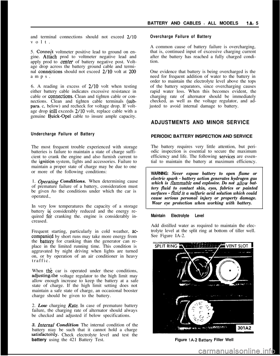
Maintain Electrolyte LevelAdd distilled water as required to maintain the elec-
trolyte level at the split ring at bottom of tiller well.
See Figure IA-2.
Figure lA-2
Battery Filler Well
Page 27 of 625
j
/lA- 61973 OPEL SERVICE MANUAL
Do not overfill, as electrolyte may
be sprayed out by
gassing or may overtlow due to heat expansion dur:
ing charging.
If distilled water is not available, it is better to add
clean, mineral-free tap water than to allow the
elec2trolyte level to remain below the top of the plates:
In freezing weather the water should be added just
before using the car or otherwise charging the bat-
tery so that the water will be mixed with the acid
before it is allowed to stand in freezing temperatures.
If it is found necessary to add water to the
batterimore frequently than about every
1,ooO miles and the
quantity of water added per cell is’ excessive, check
setting of voltage regulator and adjust, if necessary:
Abnormal water loss is an indication that the battery
is being overcharged.
Inspect Battery, Mounting and Cables
Check outside of battery for damage or signs of se&ous abuse such as broken case or broken covers:
Check inside of battery by removing the vent caps
and inspecting for signs of abuse
stich as electrolyte
level too low to see, or bad or unusual odors. If
battery shows signs of serious damage or abuse, it
should be replaced.
Check the battery hold down bolts to make certain
that battery is securely held in place. The nut should
be drawn up to 20 lbs. in.;excessjve tightening may
distort or crack the battery case.If the top of battery is dirty or the hold down str?e
is corroded, clean thoroughly with a brush dipped
IFammonia or soda solution. Care must be used td
prevent any solution from getting into battery
cellslAfter the foaming of solution stops, flush off witli
clean water and dry thoroughly. If hold down strap
is corroded it should be painted with acid-resisting
paint after cleaning.
Check battery cables to make certain they are tight
at bracket and junction block. If a connection is
found loose it should be cleaned before being tight;ened as arcing and corrosion may have taken place
in the loose connection. Check condition of cables
and replace if badly corroded or frayed.
Special attention must be given to,the battery posi-
tive cable position to eliminate the possibility of con-
tact with the exhaust manifold on the 1.1 liter engine.
The cable clamp must be rotated clockwise as neces-
sary for the cable to run at a 45 degree angle toward
the right wheelhouse panel.
Cleaning Cable Terminals
If loose connections are found by inspection, or highresistance is found by voltage test, disconnect the
cable for thorough cleaning of terminals. When
removing a corroded cable terminal from battery
post, do not pry against battery case or hammer on
terminal to break it loose, since either practice will
result in broken cell covers. Use a screw-type termi-
nal puller if terminal cannot be loosened by hand.
Thoroughly clean all corrosion from disconnected
battery cable terminals and terminal posts, using
suitable wire brushes. If wire brushes are not availa-
ble, corroded terminals may be cleaned by brushing
with a strong soda solution, using care not to get
solution into battery cells.
If
cabbz strands are broken, corroded, or loose in
terminals, the cable should be replaced with the cor-
rect cable to insure ample capacity.
To prevent corrosion of battery terminals and con-
nections, apply a coating of petroleum jelly over the
battery post and cable terminals after cables have
been installed on terminals.
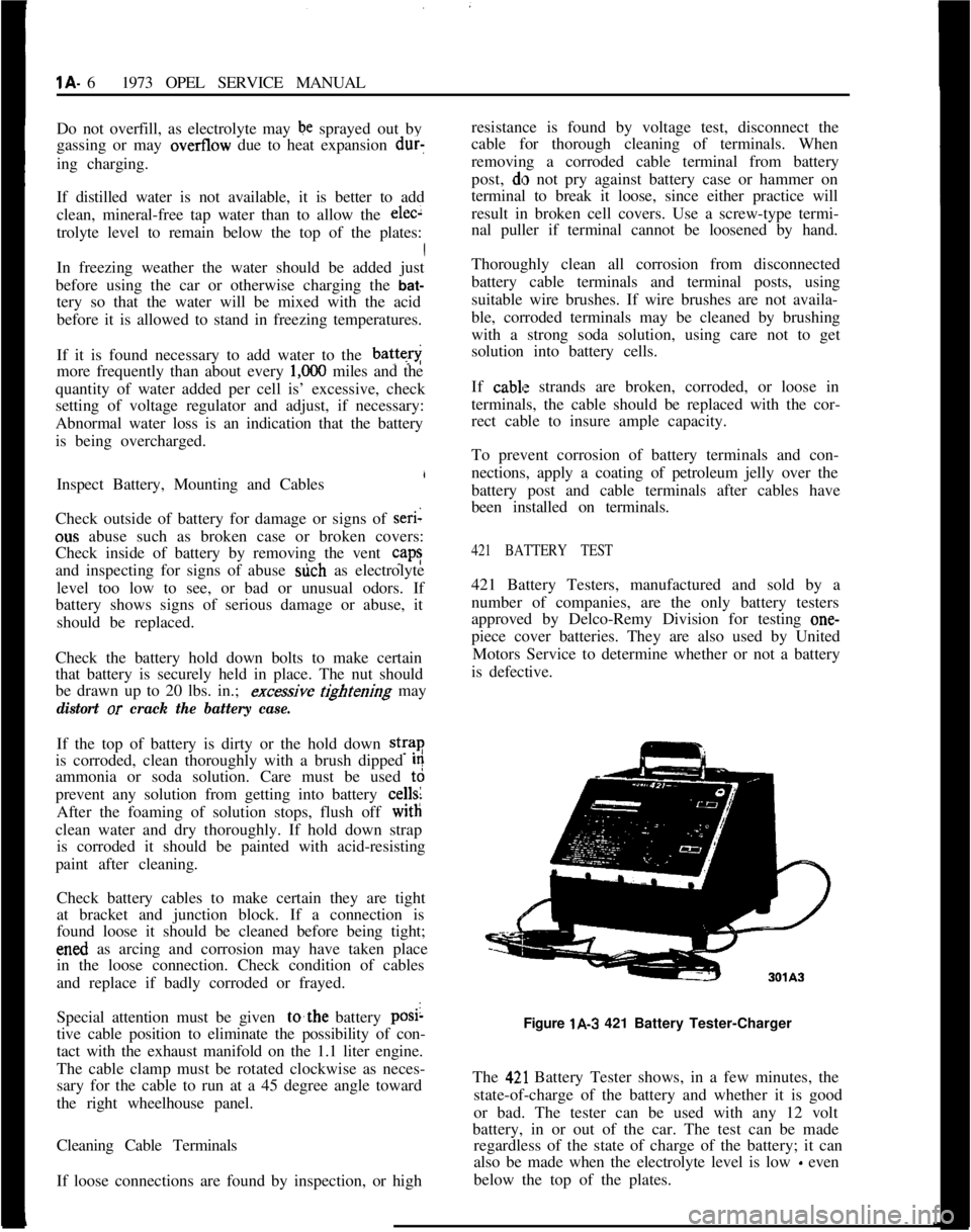
421 BATTERY TEST421 Battery Testers, manufactured and sold by a
number of companies, are the only battery testers
approved by Delco-Remy Division for testing one-
piece cover batteries. They are also used by United
Motors Service to determine whether or not a battery
is defective.
Figure lA-3 421 Battery Tester-Charger
The
42,l Battery Tester shows, in a few minutes, the
state-of-charge of the battery and whether it is good
or bad. The tester can be used with any 12 volt
battery, in or out of the car. The test can be made
regardless of the state of charge of the battery; it can
also be made when the electrolyte level is low
- even
below the top of the plates.
Page 29 of 625
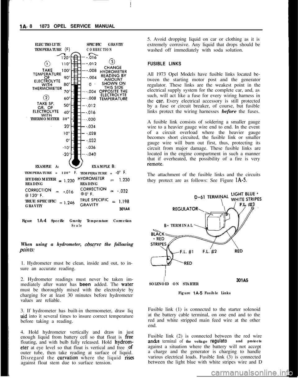
1A. 81873 OPEL SERVICE MANUALELECTROLYTESPECIFIC GRAVITY
TEMPERATURE
(F)CORRECTION
-+0&&n _
THERMOMETER 30”
EXAMPLE A:
--,012---,016---,026
- -.02h
- -.028
- -.032~
-.036
YEXAMPLE 6:TEMPERATURE = 120”
i.TEMPERATURE = -0” F.HYDROMETER = ,,230HYDRdiETER
= 1.230
READINGREADING
‘,9R2Ro~CF;‘“” = +.0,6go!RFfCilON = .,032
TRUE SPECIFIC = ,.246
GRAVITY;RU”v;,‘;CIFIC = 1.198
3xA‘l
Figure
l A-4 Specific Gravity Temperature CorrectionScale
When using a hydrometer, obsqve the following
pain Is:1. Hydrometer must be clean, inside and out, to in-
sure an accurate reading.
2. Hydrometer readings must never be taken im-
mediately after water has been added. The water
must be thoroughly mixed with the electrolyte by
charging for at least 30 minutes before hydrometer
values are reliable.
3. If hydrometer has built-in thermometer, draw liq
aid into it several times to insure correct temperature
before taking a reading.
4. Hold hydrometer vertically and draw in just
enough liquid from battery cell so that float is
freefloating, and with bulb fully released. Hold bydrom-eter at eye level so that float is vertical and free
!ofouter tube, then take reading at surface of liquid.
Disregard the curvation where the liquid rises
against float stem due to surface tension.5. Avoid dropping liquid on car or clothing as it is
extremely corrosive. Any liquid that drops should be
washed off immediately with soda solution.
FUSIBLE LINKSAll 1973 Opel Models have fusible links located be-
tween the starting motor post and the generator
regulator. These links are the weakest point in the
electrical supply system for the complete car, and, as
such, will act like a fuse for every wiring harness in
the
ca.r. Every electrical accessory is still protected
by a fuse or circuit breaker, of course, but fusible
links protect the wiring harnesses before the fuses.
A fusible link consists of soldering a smaller gauge
wire to a heavier gauge wire end to end. In the event
of a circuit overload where the heavier gauge
becomes short circuited, the fusible link or smaller
gauge wire will burn out first, thus, protecting its
circuit from major damage. These fusible links are
located in the engine compartment in such a manner
that if overheated, the possibility of a fire is veryr¬e.
The attachment of the fusible links and the circuits
they protect are as follows: See Figure
l A-5.
D+61TERMIN\AL ;;!$6,,FL #3
B+ TERMINAL
I3QlA5
SOLENOID ON STARTER
Figure
t A-5 Fusible LinksFusible link (1) is connected to the starter solenoid
at the battery cable terminal, on one end and to the
red and white stripped main feed wire at the other
end.
Fusible link (2) is connected between the red wirean&s
terminal of the voltage regulateand protectsagainst a situation where the battery will not accept
a charge and the generator is charging to handle
various electrical loads. Fusible link (3) is connected
between the light blue with white stripes wire and D
Page 30 of 625
BATTERY AND CABLES - ALL MODELSlA- 9
plus 61 terminal of the voltage regulator and protects
the circuit to the generator telltale light.
BATTERY RECHARGING
There are two separate methods of recharging batter-
ies which giffer basically in the rate of charge. In the
slow-charge method, the battery is supplied a rela-
tively small amount of current for an extended
period of time. In the quick-charge method, the bat-
tery is supplied with a high current for a short period
of time.
Slow-Charging
Slow charking is the best and only method of com-
pletely ch+rging a battery. The slow-charge method,
properly applied, may be safely used under all possi-
ble conditions of the battery, provided electrolyte is at proper
wl in all cells. The battery may be fully
charged by this method, unless the battery is not
capable of taking a full charge. The normal slow
charging rate for the
12.volt battery is 5 amperes.
Full ch&e of battery is indicated when all cell spe-
cific gravities do not increase when checked at three
intervals
of one hour and all cells are gassing freely.
Due to the low rate during slow charging, plenty of
time must ,be allowed. Charge periods of 24 hours or
more are often required.
Quick-Charging
Since time!is often of most importance to the battery
owner, quick-charging must sometimes be used to
partially charge the battery so that the engine will
start and the owner can be on his way.
Charge at:50 amperes for 20 minutes (50 times 20
equals
100Q ampere minutes). If charger will not give
this rate, charge for an equal number of ampere mi-
nutes at the best rate available. Too high a current
during quick-charging will damage battery plates.
A battery cannot be brought up to a fully charged
condition
by the quick-charge method. The battery
can be substantially recharged or boosted, but in
order to bring the battery to a fully charged condi-
tion, the charging cycle must be finished by charging
at a low
oi normal rate. Some quick-chargers have
a
provisioA for finishing the charging cycle at a low
rate so
tha’t the battery can be brought up to a fully
charged condition.
Used
with:care, and employing all safeguards prov-
ided by the manufacturer, a quick-charger will not
damage a battery
which is in good condition.
BATTERY REMOVAL AND INSTALLATION
Removal
1. Disconnect battery cables (remove negative cable
first to prevent possible shorting).
2. Remove battery hold down
l&acket.
3. Remove battery.
Installation
‘1. Place battery back in hold down position.
2. Tighten hold down bracket bolts.
3. Connect battery cables (connect positive cable first
to prevent possible shorting).
FUSIBLE LINK REMOVAL AND INSTALLATION
Replace a burned out fusible link as follows:
1. Disconnect battery.
2. Disconnect connector eye on end of fusible link.
3. Cut off other end of burned out link, along with
solder joint.
4. Strip insulation from end of new fusible link and
from end of wiring harness so that each will slide into
soldering sleeve.
5. Crimp new link in soldering sleeve and solder
carefully.
6. Cover new connection tightly with electrical tape.
I. Install new link connector eye on other end of
fusible link.
A burned out fusible link connected to the starter
solenoid would be indicated by:
1. All electrical accessories dead.
2. Starter dead - will not even click. Even with a
nearly dead battery, the starter solenoid will
gener-
ally engage; therefore, no click means no solenoid
action, possibly due to a burned out fusible link.
SPECIFICATIONS
BATTERY SPECIFICATIONS
Delco-General 12 volt-44 amp hour storage battery
is installed as original equipment. Replace with a
Delco Energizer
Y55.
Page 31 of 625
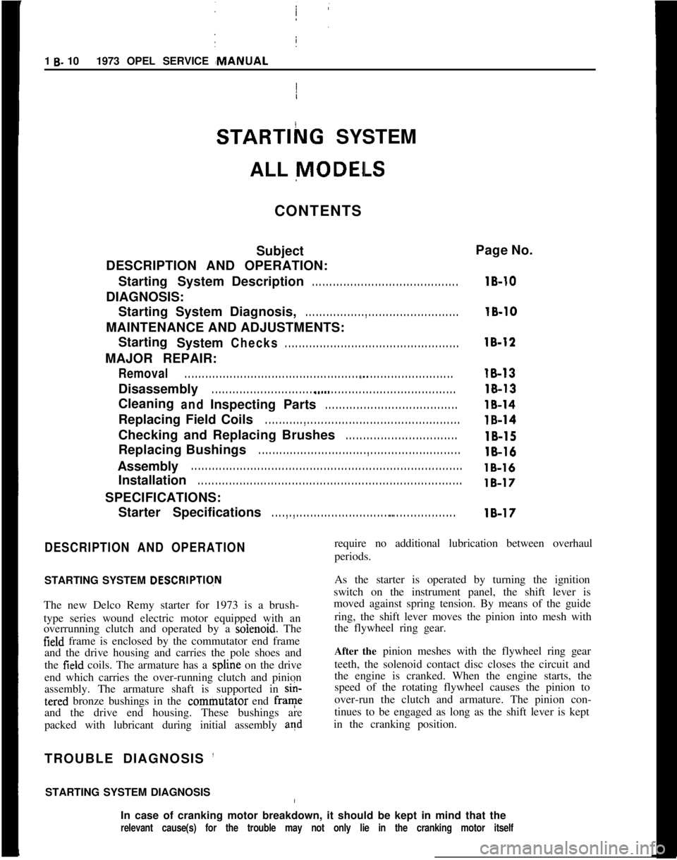
1 B- 101973 OPEL SERVICE #MANUAL
STARTlhG SYSTEM
/
ALL
MODEILS
CONTENTS
Subject
DESCRIPTION AND OPERATION:
Starting SystemDescription
. . . . . . . . . . . . . . . . . . . . . . . . . . . . . . . . . . . . \
. . . . . .
DIAGNOSIS:
Starting System Diagnosis,
. . . . . . . . . . . . . . . . . , . . . . . . . . . . . . . . . . . . \
. . . . . . . .
MAINTENANCE AND ADJUSTMENTS:Starting System
Checks. . . . . . . . . . . . . . . . . . . . . . . . . . . . . . . . . . . . \
. . . . . . . . . . . . . .
MAJOR REPAIR:
Removal. . . . . . . . . . . . . . . . . . . . . . . . . . . . . . . . . . . . \
. . . . . . . . . . . . . . . . . ., . . . . . . . . . . . . . . . . . . . . . . . . . .
Disassembly. . . . . . . . . . . . . . . . . . . . . . . . . . . . . . . a.... . . . . . . . . . . . . . . . . . . . . . . . . . . . . . . . . . . . .\
CleaningandInspecting Parts. . . . . . . . . . . . . . . . . . . . . . . . . . . . . . . . . . . . \
. .
Replacing Field Coils. . . . . . . . . . . , . . . . . . . . . . . . . . . . . . . . . . . . \
. . . . . . . . . . . . . . . . . . . .
Checking and Replacing Brushes. . . . . . . . . . . . . . . . . . . . . . . . . . . . . . . .
Replacing Bushings. . . . . . . . . . . . . . . . . . . . . . . . . . . . . . . , . . . . \
. . . . . . . . . . . . . . . . . . . . . .
Assembly. . . . . . . . . . . . . . . . . . . . . . . . . . . . . . . . . . . . \
. . . . . . . . . . . . . . . . . . . . . . . . . . . . . . . . . . . . \
. . . . . .
Installation. . . . . . . . . . . . . . . . . . . . . . . . . . . . . . . . . . . . \
. . . . . . . . . . . . . . . . . . . . . . . . . . . . . . . . . . . . \
. . . .
SPECIFICATIONS:
Starter Specifications
. . . . , . , . . . . . . . . . . . . . . . . . . . . . . . . . . . . . . . . . . . . . . . . . . . . . . .
Page No.
lB-10
16-10
18-12
18-13
18-13
18-14
18-14
16-15
18-16
lB-16
18-17
18-17
DESCRIPTION AND OPERATION
STARTING SYSTEM DESCRlPTlqN
The new Delco Remy starter for 1973 is a brush-
type series wound electric motor equipped with an
overrunning clutch and operated by a
soienoid. The
field frame is enclosed by the commutator end frame
and the drive housing and carries the pole shoes and
the
field coils. The armature has a spline on the drive
end which carries the over-running clutch and pinion
assembly. The armature shaft is supported in
sin-
tered bronze bushings in the commtitator end frame
and the drive end housing. These bushings are
packed with lubricant during initial assembly
and
TROUBLE DIAGNOSIS ’
STARTING SYSTEM DIAGNOSIS/
require no additional lubrication between overhaul
periods.
As the starter is operated by turning the ignition
switch on the instrument panel, the shift lever is
moved against spring tension. By means of the guide
ring, the shift lever moves the pinion into mesh with
the flywheel ring gear.
After the pinion meshes with the flywheel ring gear
teeth, the solenoid contact disc closes the circuit and
the engine is cranked. When the engine starts, the
speed of the rotating flywheel causes the pinion to
over-run the clutch and armature. The pinion con-
tinues to be engaged as long as the shift lever is kept
in the cranking position.
In case of cranking motor breakdown, it should be kept in mind that the
relevant cause(s) for the trouble may not only lie in the cranking mot\
or itself
Page 33 of 625
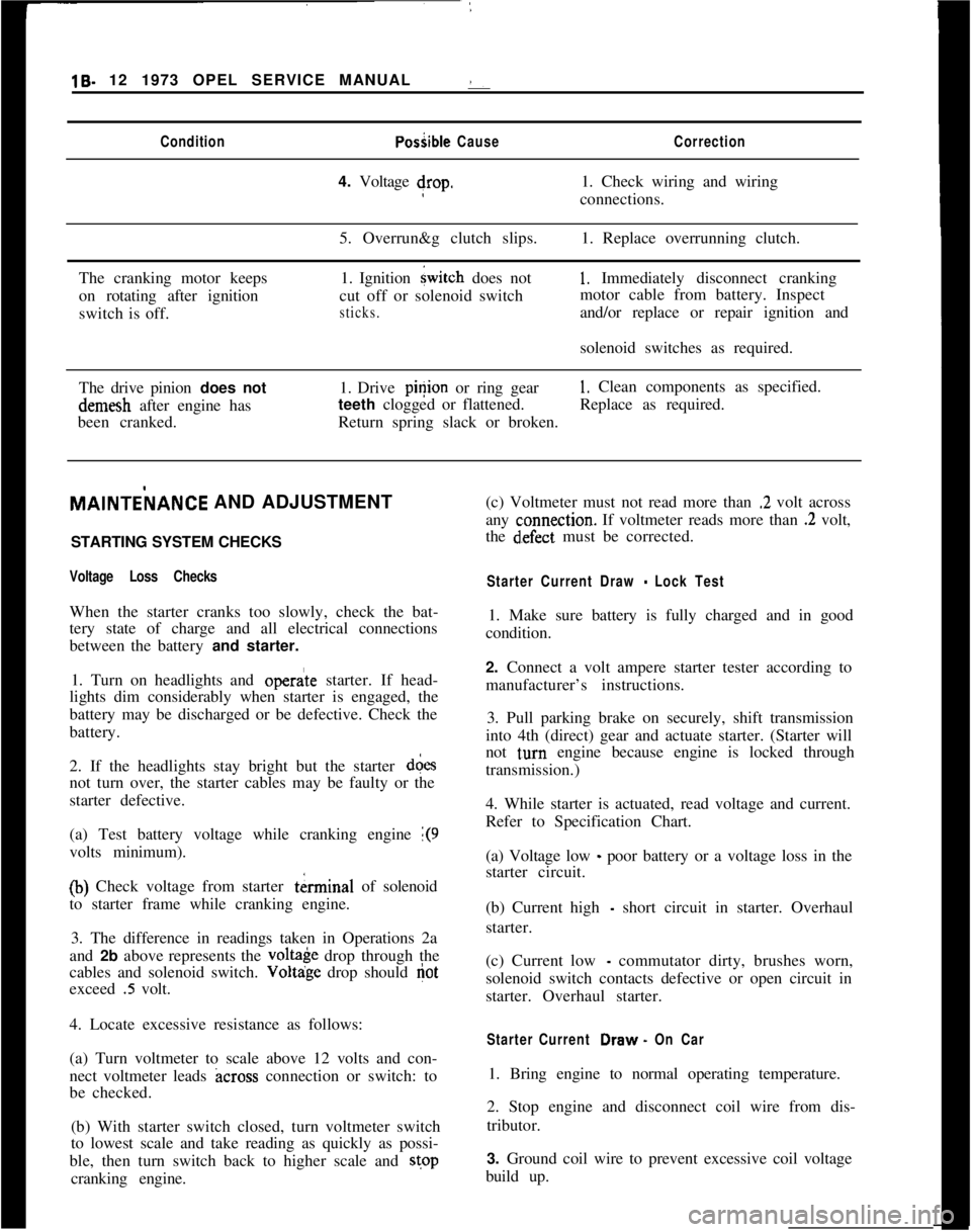
19- 12 1973 OPEL SERVICE MANUAL :ConditionPosiible CauseCorrection4. Voltage drop.1. Check wiring and wiring
connections.
5. Overrun&g clutch slips.1. Replace overrunning clutch.
The cranking motor keeps
on rotating after ignition
switch is off.1. Ignition
{witch does not
cut off or solenoid switch
sticks.
1, Immediately disconnect cranking
motor cable from battery. Inspect
and/or replace or repair ignition and
solenoid switches as required.
The drive pinion does notdemesh after engine has
been cranked.1. Drive pinion or ring gear
1. Clean components as specified.
teeth clogged or flattened.Replace as required.
Return spring slack or broken.MAlNTEilANCE AND ADJUSTMENT
/
STARTING SYSTEM CHECKS
Voltage Loss ChecksWhen the starter cranks too slowly, check the bat-
tery state of charge and all electrical connections
between the battery and starter.
1. Turn on headlights and
opera’te starter. If head-
lights dim considerably when starter is engaged, the
battery may be discharged or be defective. Check the
battery.
2. If the headlights stay bright but the starter d&s
not turn over, the starter cables may be faulty or the
starter defective.
(a) Test battery voltage while cranking engine
1(9volts minimum).
(b) Check voltage from starter tkrminal of solenoid
to starter frame while cranking engine.
3. The difference in readings taken in Operations 2a
and 2b above represents the
volt& drop through the
cables and solenoid switch. Voltdge drop should
Gotexceed
.5 volt.
4. Locate excessive resistance as follows:
(a) Turn voltmeter to scale above 12 volts and con-
nect voltmeter leads
across connection or switch: to
be checked.
(b) With starter switch closed, turn voltmeter switch
to lowest scale and take reading as quickly as possi-
ble, then turn switch back to higher scale and stop
cranking engine.(c) Voltmeter must not read more than
.2 volt across
any
c:onnection. If voltmeter reads more than .2 volt,
the
d~efect must be corrected.
Starter Current Draw - Lock Test1. Make sure battery is fully charged and in good
condition.
2. Connect a volt ampere starter tester according to
manufacturer’s instructions.
3. Pull parking brake on securely, shift transmission
into 4th (direct) gear and actuate starter. (Starter will
not
t,urn engine because engine is locked through
transmission.)
4. While starter is actuated, read voltage and current.
Refer to Specification Chart.
(a) Voltage low
_ poor battery or a voltage loss in the
starter circuit.
(b) Current high
- short circuit in starter. Overhaul
starter.
(c) Current low
- commutator dirty, brushes worn,
solenoid switch contacts defective or open circuit in
starter. Overhaul starter.
Starter Current Draw. On Car1. Bring engine to normal operating temperature.
2. Stop engine and disconnect coil wire from dis-
tributor.
3. Ground coil wire to prevent excessive coil voltage
build up.