boot OPEL GT-R 1973 Service Manual
[x] Cancel search | Manufacturer: OPEL, Model Year: 1973, Model line: GT-R, Model: OPEL GT-R 1973Pages: 625, PDF Size: 17.22 MB
Page 42 of 625
IGNITION SYSTEMlC-214. Rota&distributor counterclockwise slightly until
contact pbints just start to open. This must be done
very carefully or engine will not start.
5. Install distributor cap. Make sure spark plug wires
are correctly installed in distributor cap, through clip
and on spark plugs.
Finish TimingIContact boint gap
(.016” at widest gap) or dwell 50
degrees plus or minus 3 degrees should always be
checked before adjusting ignition timing.
1. Connekt timing light to No. 1 spark plug.
2. Disconnect and plug vacuum advance unit and
retard u$it hoses.
3. Connect a tachometer from distributor side of coil
to
groun$l.4. Start dngine. Set idle speed to 900 RPM.
5. Rotate distributor as necessary to align timing
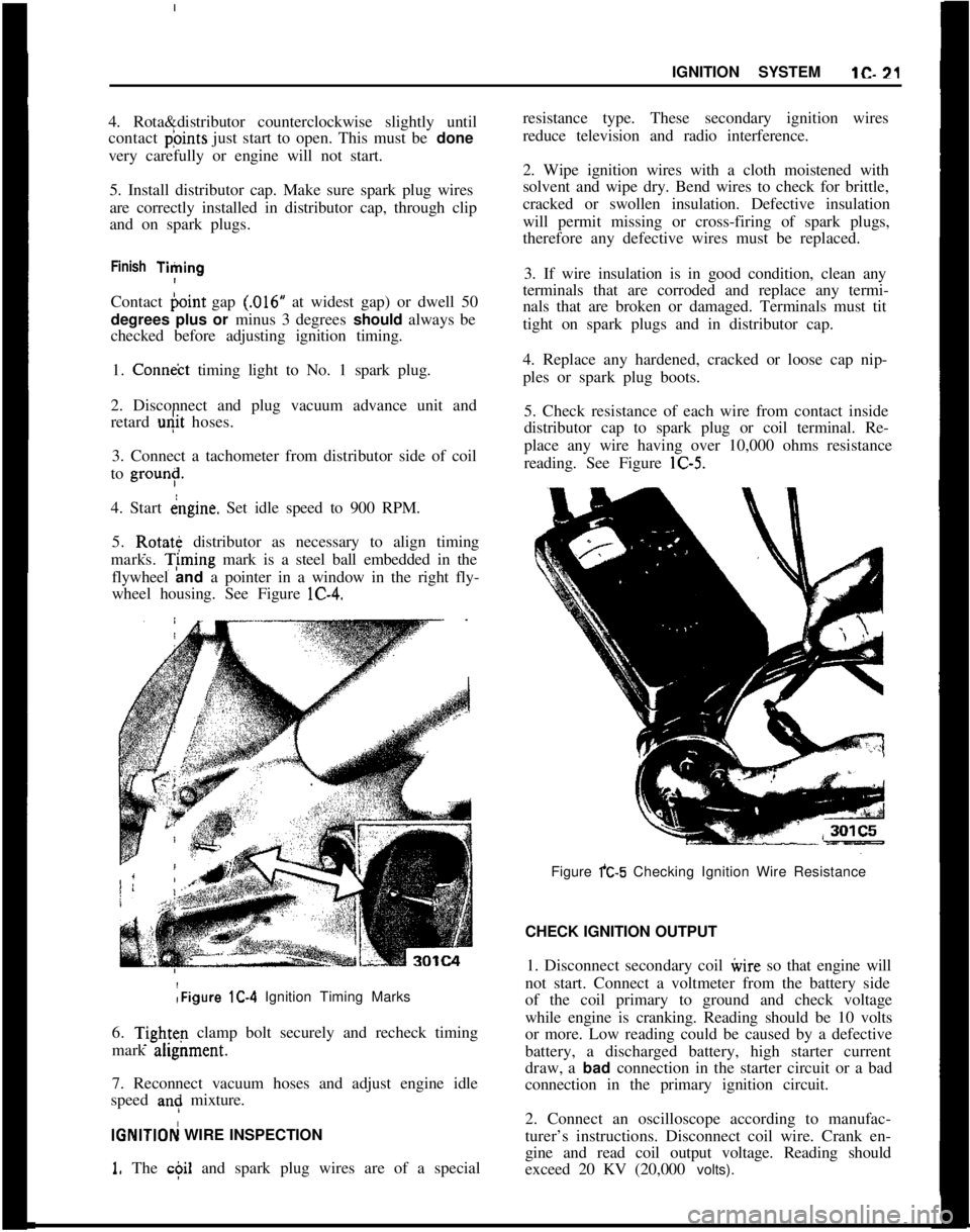
marks. T;ming mark is a steel ball embedded in the
flywheel and a pointer in a window in the right fly-
wheel housing. See Figure lC-4.:Figure lC-4 Ignition Timing Marks
6.
Tightq clamp bolt securely and recheck timing
mark ahgnment.
7. Reconnect vacuum hoses and adjust engine idle
speed
an: mixture.
IGNlTlOFj WIRE INSPECTION
1. The c$il and spark plug wires are of a specialresistance type. These secondary ignition wires
reduce television and radio interference.
2. Wipe ignition wires with a cloth moistened with
solvent and wipe dry. Bend wires to check for brittle,
cracked or swollen insulation. Defective insulation
will permit missing or cross-firing of spark plugs,
therefore any defective wires must be replaced.
3. If wire insulation is in good condition, clean any
terminals that are corroded and replace any termi-
nals that are broken or damaged. Terminals must tit
tight on spark plugs and in distributor cap.
4. Replace any hardened, cracked or loose cap nip-
ples or spark plug boots.
5. Check resistance of each wire from contact inside
distributor cap to spark plug or coil terminal. Re-
place any wire having over 10,000 ohms resistance
reading. See Figure lC-5.
Figure fC-5 Checking Ignition Wire Resistance
CHECK IGNITION OUTPUT
1. Disconnect secondary coil ivire so that engine will
not start. Connect a voltmeter from the battery side
of the coil primary to ground and check voltage
while engine is cranking. Reading should be 10 volts
or more. Low reading could be caused by a defective
battery, a discharged battery, high starter current
draw, a bad connection in the starter circuit or a bad
connection in the primary ignition circuit.
2. Connect an oscilloscope according to manufac-
turer’s instructions. Disconnect coil wire. Crank en-
gine and read coil output voltage. Reading should
exceed 20 KV (20,000 volts).
Page 43 of 625
lC- 22 1973 OPEL SERVICE MANUAL j
3. Start engine and disconnect a wire from a spark
plug. Read output voltage of disconnected spark
plug circuit. Reading should exceed 20 KV
(20,poO
volts).I
CHECK DISTRIBUTOR
!1. Clean distributor cap and inspect it for cracks or
tracking. Inspect inner segments for erosion and
outer sockets for corrosion.
2. Clean and inspect ignition wires. Make sure resist-
ance of each wire is less than 10,000 ohms. Replace
any defective spark plug boots or distributor
capnipples. See paragraph lC-12.
3. Inspect breaker points and replace if necessary.
Adjust breaker point gap to
,016 inch with rubbing
block on peak of cam lobe or check dwell and adjust
if not 50 degrees plus or minus 3 degrees. 4. Check
dwell variation by reading dwell at idle and at 3000
RPM. Dwell must not vary more than 3 degrees.
Excessive variation means distributor shaft, cam or
breaker plate are worn or damaged--overhaul dis-
tributor and replace defective parts.
5. Check distributor condenser for a minimum series
resistance and insulation leakage. Check for a
capacity between
.15 and .20 microfarads.
6. Check total advance (centrifugal and vacuum) at
2500 engine RPM using a timing light having a dial
for reading advance.
(a) The timing marks are aligned with both the
vacuum advance and the vacuum retard hoses dis-
connected and plugged.
Engine idle should be 900 RPM.
(b) Reconnect vacuum hoses. Run engine at
3600RPM and adjust knob until timing marks are
aligned. Read advance on dial. Maximum centrifugal
advance should be between 28-32 degrees.
7. If total advance is out of specifications, check
centrifugal advance only, at
2500 RPM. Discon+ectand plug all vacuum hoses. Maximum vacuum ad-
vance should be l-5 degrees at 4.5-5.0 in. hg.
8. Replace centrifugal or vacuum advance parts as
required to bring distributor total advance within
specifications.
9. Check operation of vacuum retard unit (rear unit)
by first making sure timing marks are aligned with
vacuum hoses disconnected and at slow idle (700
RPM). Then connect vacuum hose to vacuum retard
unit (rear unit). Timing ball should move in a retard
direction (upward).
CHEICK SPARK PLUGS1. Remove spark plugs. If electrodes are badly worn,
discard plugs. If inner or outer porcelain is cracked
or broken, discard plugs.
2. Note color and general appearance of inner end of
spark plug. Brown to grayish
- tan deposits and slight
electrode wear indicate correct spark plug heat
range. Plugs having this appearance may be cleaned,
regapped, tested and reinstalled.
3. Clean spark plugs in a sand blast type cleaner.
Clean only enough to remove deposits, not enough to
wear away porcelain. If deposits are too hard to
remove or if porcelain is glazed, discard plugs.
4. After cleaning spark plugs, clean tiring surfaces of
electrodes with a line file.
5. Test cleaned spark plugs on a pressure tester by
comparing spark of the used plugs with that of a new
plug. Install tested plugs, using new gaskets.
6. If removed spark plugs have excessive carbon foul-
ing and if the car will be driven mostly at low speeds
in city driving, it is advisable to replace plugs with
a hotter plug, AC43FS.
7. If removed plugs show rapid electrode wear or
inner porcelain breakage at low mileage. Check for
a vacuum leak such as a poor manifold to head fit.
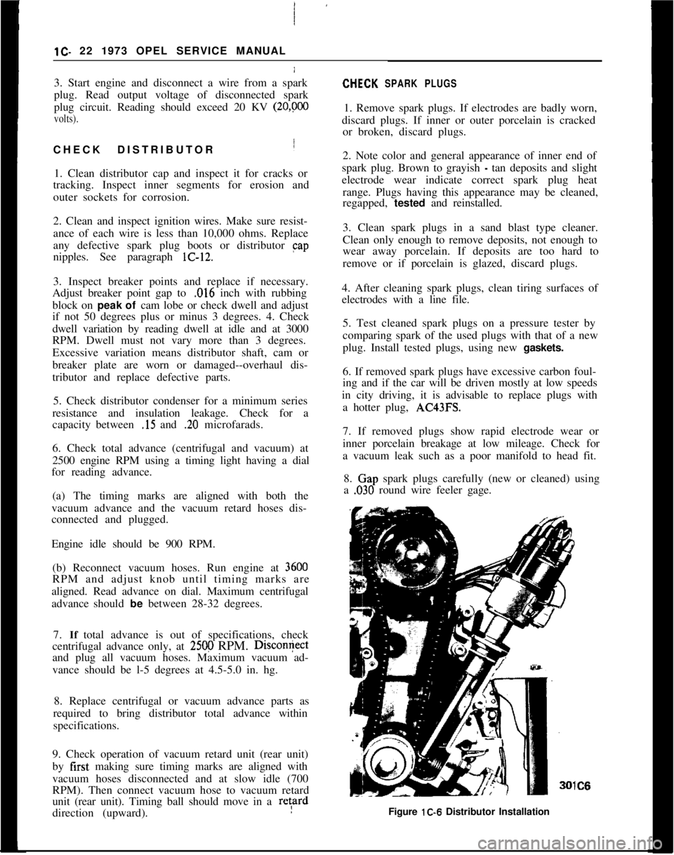
8.
Clap spark plugs carefully (new or cleaned) using
a
,030 round wire feeler gage.IC6
Figure lC-6 Distributor Installation
Page 46 of 625
IGNITION SYSTEM1C. 25
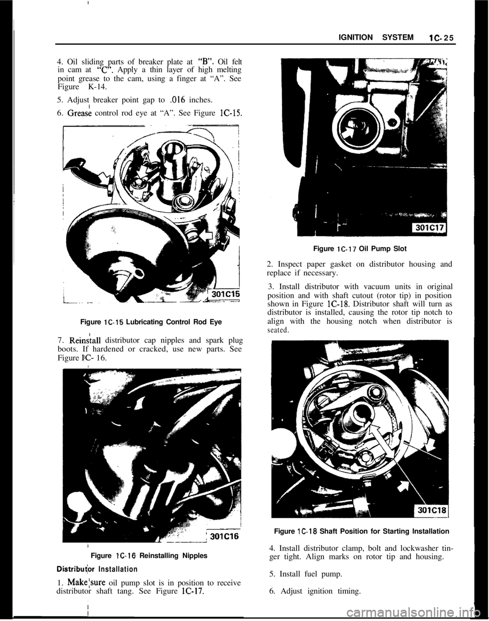
4. Oil sliding parts of breaker plate at “B”. Oil felt
in cam at
“c”. Apply a thin layer of high melting
point grease to the cam, using a finger at “A”. See
Figure K-14.
/
5. Adjust breaker point gap to
,016 inches.
6. Grease control rod eye at “A”. See Figure lC-15.
Figure lC-15 Lubricating Control Rod Eye
7. Rein&all distributor cap nipples and spark plug
boots. If hardened or cracked, use new parts. See
Figure
l!C- 16.
/ Figure lC-16 Reinstalling Nipples
Distribu
2. Inspect paper gasket on distributor housing and
replace if necessary.
3. Install distributor with vacuum units in original
position and with shaft cutout (rotor tip) in position
shown in Figure lC-18. Distributor shaft will turn as
distributor is installed, causing the rotor tip notch to
align with the housing notch when distributor is
seated.Figure
1C-18 Shaft Position for Starting Installation
4. Install distributor clamp, bolt and lockwasher tin-
ger tight. Align marks on rotor tip and housing.
5. Install fuel pump.
6. Adjust ignition timing.
Page 195 of 625
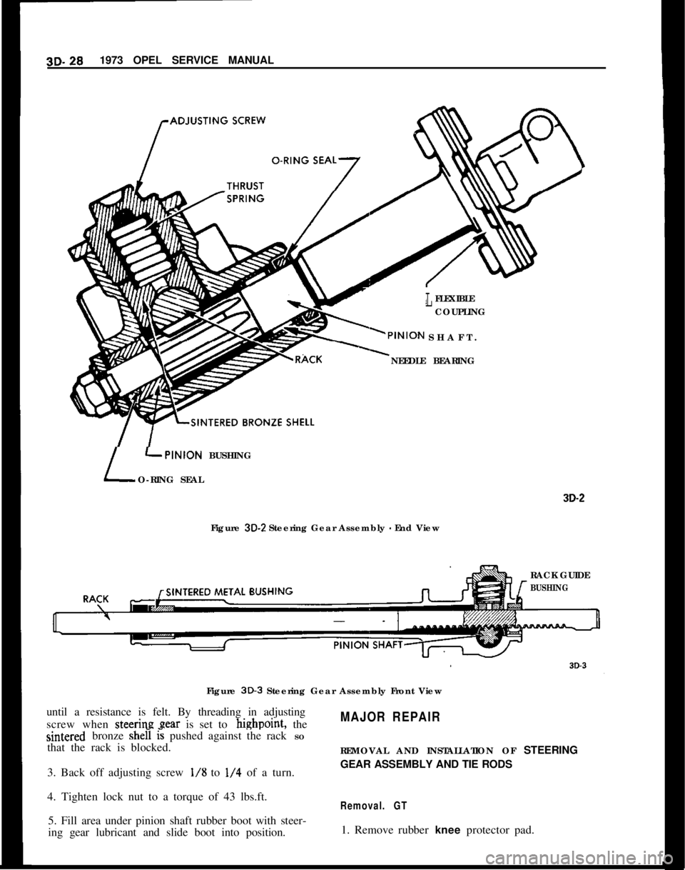
3D. 281973 OPEL SERVICE MANUALr
LFLEXIBLE
COUPLING
SHAFT.
NEEDLE BEARING
L
LPINION BUSHING
O-RING SEAL
Figure
3D-2 Steering Gear Assembly - End View
3D-2RACK GUIDE
rBUSHINGFigure
3D-3 Steering Gear Assembly Front View
until a resistance is felt. By threading in adjusting
screw when steering gear is set to highpoint, the
MAJOR REPAIRsintered bronze she0
l’s pushed against the rack SO
that the rack is blocked.
REMOVAL AND INSTALLATION OF STEERING
3. Back off adjusting screw
l/8 to l/4 of a turn.GEAR ASSEMBLY AND TIE RODS
4. Tighten lock nut to a torque of 43 lbs.ft.
Removal. GT5. Fill area under pinion shaft rubber boot with steer-
ing gear lubricant and slide boot into position.1. Remove rubber knee protector pad.
Page 201 of 625
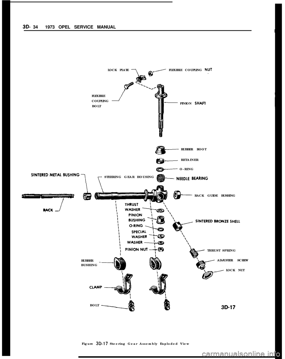
3D- 341973 OPEL SERVICE MANUALILOCK PLATE
7, @-, FLEXIBLE COUPLING NUTFLEXIBLE
COUPLING
-/BOLTPINION SHAFI
RUBBER BOOT
es+--RETAINER
ew O-RING
‘lNTERED METAL BUSHING 1y STEERING GEAR HOUSING @+ NEEDLE
BEARlNG
y-7RACK GUIDE BUSHING
RACK
he---THRUST SPRINGiRUBBERADJUSTER SCREW
BUSHING
ILOCK NUT
BOLT
\Figure 3D-17 Steering Gear Assembly Exploded View30-17
Page 261 of 625
CONTENTS
SubjectPage No.
DESCRIPTION AND OPERATION:
Power
BrakeBooster. . . . . . . . . . . . . . . . . . . . . . . . . . . . . . . . . . . . . . . . . . . . . . . . . . . . . . . .Master
Cylinder
. . . . . . . . . . . . . . . . . . . . . . . . . . . . . . . . . . . . . . . . . . . . . . . . . . . . . . . . . . . . . . . . . .DIAGNOSIS:
Power
Brake
,UnitTroubleDiagnosis. . . . . . . . . . . . . . . . . . . . . . . . . .MAINTENANCE AND ADJUSTMENTS:
Checking Brake Booster Operation
. . . . . . . . . . . . . . . . . . . . . . . . . . . .Brake Booster Filter Service
. . . . . . . . . . . . . . . . . . . . . . . . . . . . . . . . . . . . . . . . . ..Vacuum Control Valve Service
. . . . . . . . . . . . . . . . . . . . . . . . . . . . . . . . . . . . . .MAJOR REPAIR:
5A-2
5A-2SA-4SA-5
5A-65A-6
Brake Booster Removal and Installation
. . . . . . . . . . . . . . . . . .Master Cylinder Overhaul
. . . . . . . . . . . . . . . . . . . . . . . . . . . . . . . . . . * . . . . . . . . . . .SPECIFICATIONS:
General
Specifications
. . . . . . . . . . . . . . . . . . . . . . . . . . . . . . . . . . . . . . . . . . . . . . . . . . . . . .SA-6
5A-7
5A-95A. 21973 OPEL SERVICE MANUAL
POWER BRAKE BOOSTER AND MASTER CYLINDER
DESCRIPTION AND OPERATION
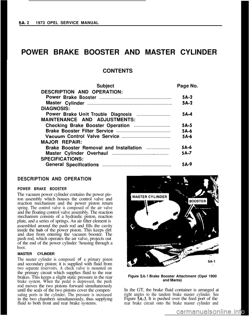
POWER BRAKE BOOSTERThe vacuum power cylinder contains the power pis-
ton assembly which houses the control valve and
reaction mechanism and the power piston return
spring. The control valve is composed of the air valveand the floating control valve assembly. The reaction
mechanism consists of a hydraulic piston, reaction
plate, and a series of springs. An air filter element is
assembled around the push rod and fills the cavity
inside the hub of the power piston. This keeps dirt
and dust from entering the vacuum booster. The
push rod, which operates the air valve, projects out
of the end of the power cylinder ‘housing through a
boot.MASTER CYLINDER
The master cylinder is composed pf a primary pistonand secondary piston; it is supplied with fluid from
two separate reservoirs. A check valve is mounted onthe primary circuit which supplies fluid to the rear
brakes. This keeps a slight static pressure in the rear
brake system. When the pedal is depressed, the pushrod moves the two pistons forward simultaneously
until the seals of the two pistons cover the compen-
sating ports in the cylinder. The pressure is increasedin the two chambers simultaneously, thus supplying
fluid to both front and rear brake systems.Figure
5A-1 Brake Booster Attachment (Opel 1900
and Manta)
In the GT, the brake fluid container is arranged at
right angles to the tandem brake master cylinder. SeeFigure
5A-3. It is pushed over the feed port of the
rear brake circuit onto the brake master cylinder and
Page 265 of 625
5A- 61973 OPEL SERVICE MANUAL
ing on dusty and sandy roads - the filter and sound
deadener should occasionally be replaced. To do so,
brake booster has to be removed without detaching
brake master cylinder.
Proceed as follows:
1. Remove protective cap (boot).
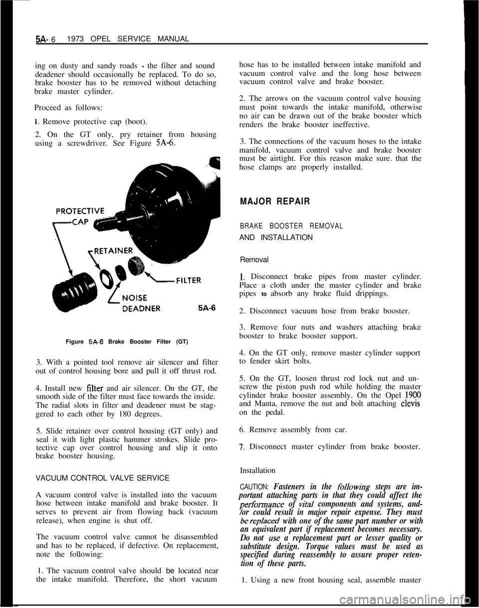
2. On the GT only, pry retainer from housing
using a screwdriver. See Figure
SA-6.Figure 5A-6 Brake Booster Filter (GT)
3. With a pointed tool remove air silencer and filter
out of control housing bore and pull it off thrust rod.
4. Install new filter and air silencer. On the GT, the
smooth side of the filter must face towards the inside.
The radial slots in filter and deadener must be stag-
gered to each other by 180 degrees.
5. Slide retainer over control housing (GT only) and
seal it with light plastic hammer strokes. Slide pro-
tective cap over control housing and slip it onto
brake booster housing.
VACUUM CONTROL VALVE SERVICE
A vacuum control valve is installed into the vacuum
hose between intake manifold and brake booster. It
serves to prevent air from flowing back (vacuum
release), when engine is shut off.
The vacuum control valve cannot be disassembled
and has to be replaced, if defective. On replacement,
note the following:
1. The vacuum control valve should be located near
the intake manifold. Therefore, the short vacuumhose has to be installed between intake manifold and
vacuum control valve and the long hose between
vacuum control valve and brake booster.
2. The arrows on the vacuum control valve housing
must point towards the intake manifold, otherwise
no air can be drawn out of the brake booster which
renders the brake booster ineffective.
3. The connections of the vacuum hoses to the intake
manifold, vacuum control valve and brake booster
must be airtight. For this reason make sure. that the
hose clamps are properly installed.
MAJOR REPAIR
BRAKE BOOSTER REMOVALAND INSTALLATION
Removal
1. Disconnect brake pipes from master cylinder.
Place a cloth under the master cylinder and brake
pipes to absorb any brake fluid drippings.
2. Disconnect vacuum hose from brake booster.
3. Remove four nuts and washers attaching brake
booster to brake booster support.
4. On the GT only, remove master cylinder support
to fender skirt bolts.
5. On the GT, loosen thrust rod lock nut and un-
screw the piston push rod while holding the master
cylinder brake booster assembly. On the Opel
1900and Manta, remove the nut and bolt attaching clevis
on the pedal.
6. Remove assembly from car.
7. Disconnect master cylinder from brake booster.
Installation
CAUTION: Fasteners in the folkwing steps are im-
portant attaching parts in that they could affect the
performance of vital components and systems, and-
/or could result in major repair expense. They must
berep/aced, with one of the same part number or with
an equivalent part if replacement becomes necessary.
Do not
use a replacement part or lesser quality or
substitute design. Torque values must be used as
specified during reassembly to assure proper reten-
tion of these parts.1. Using a new front housing seal, assemble master
Page 284 of 625
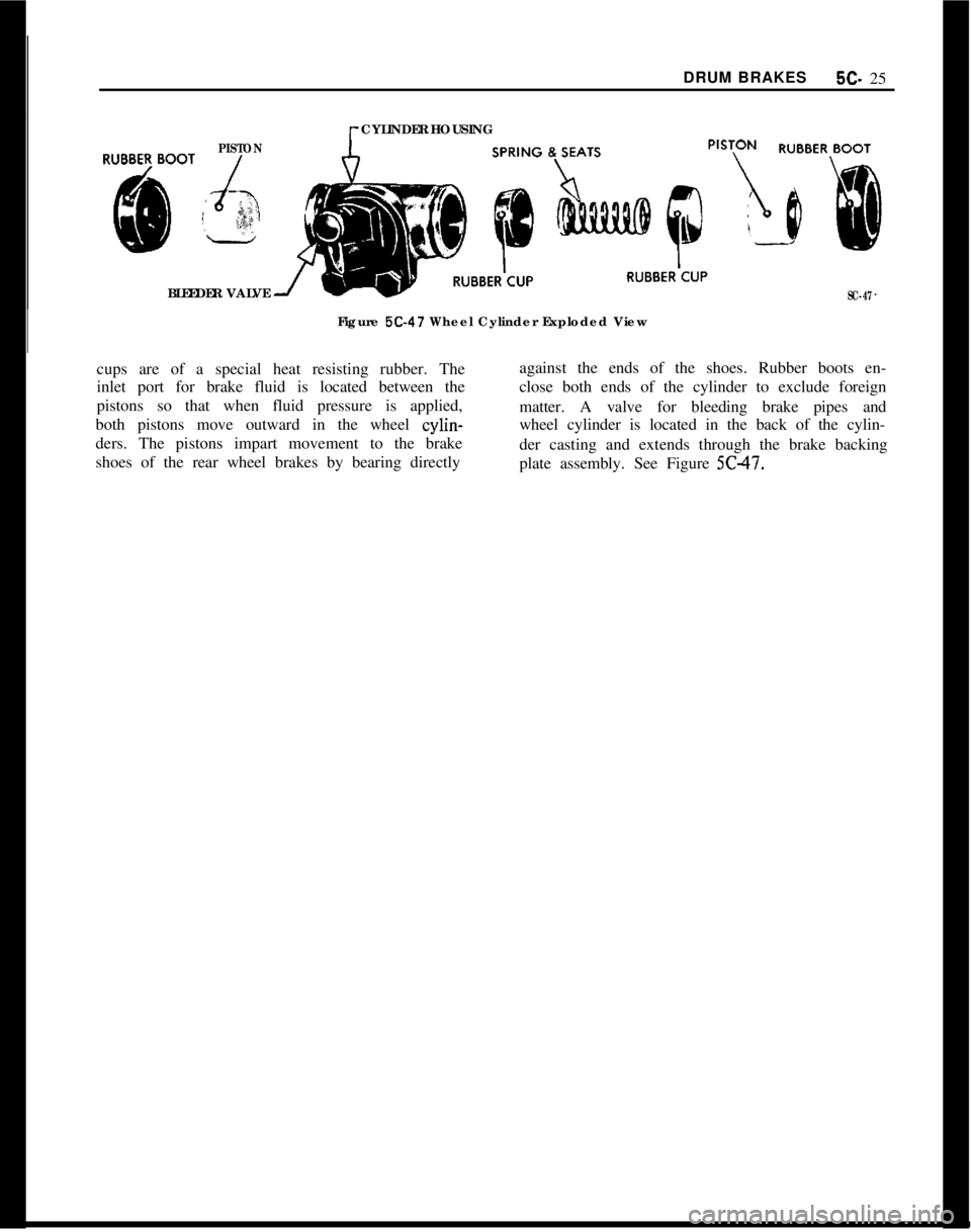
DRUM BRAKES5C- 25PISTONCYLINDER HOUSING
BLEEDER VALVE
SC-47Figure
5C-47 Wheel Cylinder Exploded View
cups are of a special heat resisting rubber. Theagainst the ends of the shoes. Rubber boots en-
inlet port for brake fluid is located between theclose both ends of the cylinder to exclude foreign
pistons so that when fluid pressure is applied,
matter. A valve for bleeding brake pipes and
both pistons move outward in the wheel cylin-wheel cylinder is located in the back of the cylin-
ders. The pistons impart movement to the brake
der casting and extends through the brake backing
shoes of the rear wheel brakes by bearing directly
plate assembly. See Figure 5C47.
Page 288 of 625
DRUM BRAKESBC- 29
at a time to avoid getting fluid level in reservoir
dangerously low. The correct sequence for bleeding
is bleed the wheel cylinder or caliper nearest the
master cylinder first in either circuit.
Do not perform bleeding operation while any brake
drum is removed.
Bleeding Wheel Cylinder or Caliper
1. Check fluid level, in reservoir and refill, if neces-
sary. Level must be brought up to “MAX” mark on
plastic reservoir.
2. Clean all dirt from around respective bleeder
valve, and then remove cap.
3. Push bleeder hose over bleeder valve, placing
other end of hose in a glass jar. Bleeder hose should
always be used to avoid getting fluid on linings.
4. Hold pressure on brake pedal and crack open the
bleeder valve to allow air (and,or) brake fluid to flow
out of the system. Allow pedal to travel to the floor.
Close bleeder valve. Release pedal and repeat this
procedure at each wheel cylinder in the circuit until
all air is removed. Frequently check reservoir fluid
level. Allowing fluid to be emptied will draw air into
the system.
5. Remove bleeder hose and install cap.
6. When bleeding operation is completed, make sure
that fluid level is brought up to “MAX” marking on
reservoir, then install cover.
7. Discard the brake fluid deposited in glass jar dur-
ing bleeding operation.
Flushing Brake Hydraulic System
It is recommended that both brake system circuits be
thoroughly flushed whenever the master cylinder is
replaced or if there is any doubt as to the grade of
fluid in the system.
Flushing of the brake system is performed in the
same manner as the bleeding operation except that
fluid is forced through the lines and wheel cylinder
until it emerges clear in color. Approximately one
half pint of brake fluid is required to flush the hy-
draulic system thoroughly.
When flushing is completed, make certain the master
cylinder reservoir is filled to the proper level.Figure
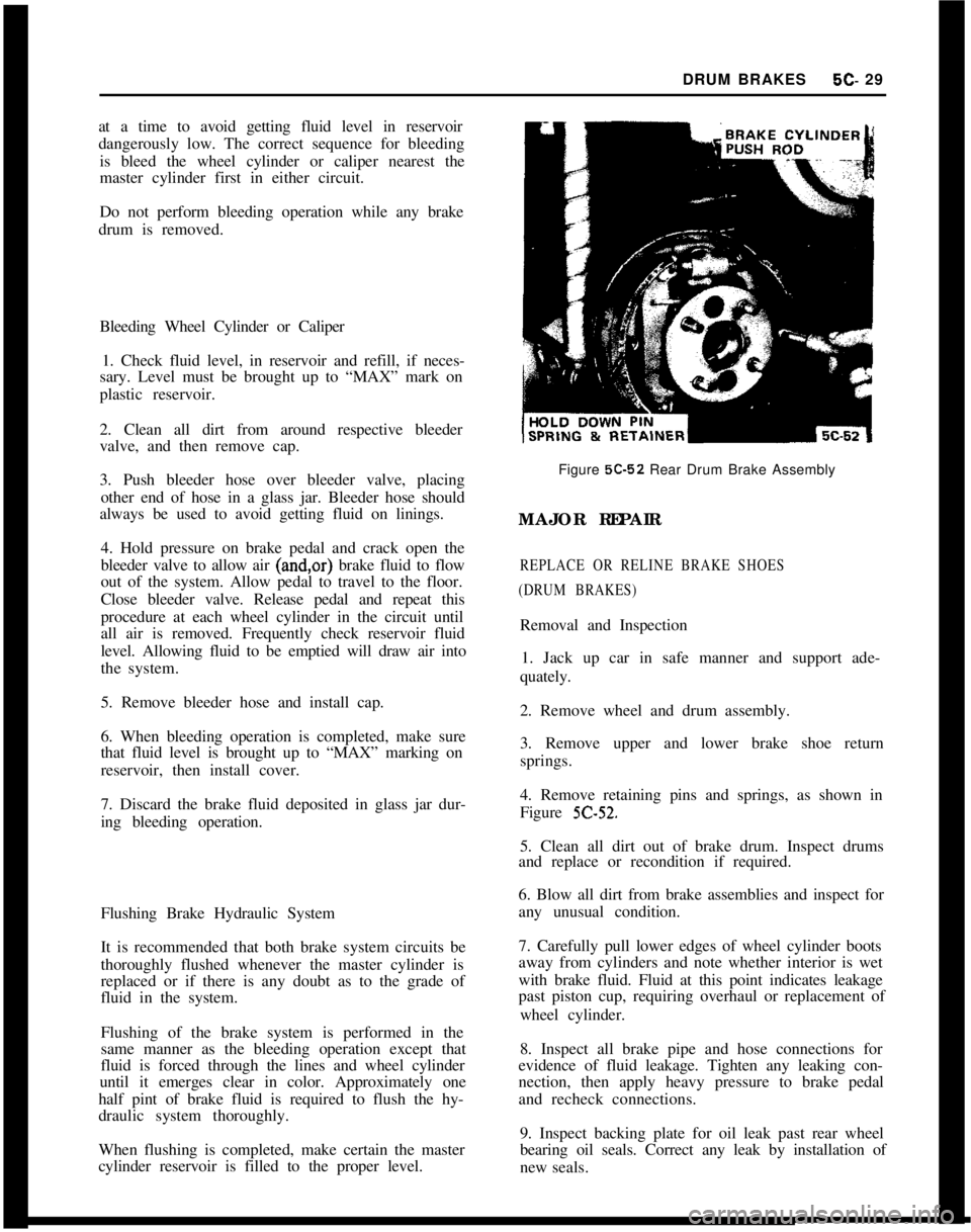
5C-52 Rear Drum Brake Assembly
MAJOR REPAIR
REPLACE OR RELINE BRAKE SHOES
(DRUM BRAKES)Removal and Inspection
1. Jack up car in safe manner and support ade-
quately.
2. Remove wheel and drum assembly.
3. Remove upper and lower brake shoe return
springs.
4. Remove retaining pins and springs, as shown in
Figure
5C-52.5. Clean all dirt out of brake drum. Inspect drums
and replace or recondition if required.
6. Blow all dirt from brake assemblies and inspect for
any unusual condition.
7. Carefully pull lower edges of wheel cylinder boots
away from cylinders and note whether interior is wet
with brake fluid. Fluid at this point indicates leakage
past piston cup, requiring overhaul or replacement of
wheel cylinder.
8. Inspect all brake pipe and hose connections for
evidence of fluid leakage. Tighten any leaking con-
nection, then apply heavy pressure to brake pedal
and recheck connections.
9. Inspect backing plate for oil leak past rear wheel
bearing oil seals. Correct any leak by installation of
new seals.
Page 290 of 625
DRUM BRAKES5c- 31
remove grooves, and the ridges in the lining should
be lightly removed with a lining grinder.
If brake linings are more than half worn, but do not
need replacement, the drum should be polished with
fine emery cloth but should not be rebored. At this
stage, eliminating the grooves in drum and smooth-
ing the ridges on lining would necessitate removal of
too much metal and lining, while if left alone, the
grooves and ridges match and satisfactory service
can be obtained.
If brake linings are to be replaced, a grooved drum
should be rebored for use with oversize linings. A
grooved drum, if used with new lining, will not only
wear the lining but will make it
diff%xlt, if not im-
possible, to obtain etXcient brake performance.
Out-of-Round DrumAn out-of-round drum makes accurate brake shoe
adjustment impossible and is likely to cause excessive
wear of other parts of brake mechanism due to its
eccentric action. An out-of-round drum can also
cause brake pulsation. Maximum permissible drumrunout is 004”. A drum that has more run-out than
this should be rebored. Runout can be accurately
checked by using an inside micrometer fitted with
proper extension rods.
When measuring a drum for run-out, take measure-
ments at open and closed edges of machined surface
and at right angles to each other.
Turning Brake DrumsIf a brake drum is to be turned, enough metal should
be removed to obtain a true, smooth braking surface.
Measure brake drum diameter; standard drum inner
diameter is 9.060”. Drums may be turned to an over-
size of ,030”. If maximum inner diameter after turn-
ing exceeds 9.090”, brake drum will have to be
replaced. Removal of more metal will affect dissipa-
tion of heat and may cause distortion of the drum.
1. Remove rear wheels and drums.
2. Mount brake drum on brake drum lathe and turn
drums as necessary, within limits.
3. After turning, check drum diameter. Inner diame-
ter not to exceed 9.090.
4. A newly-bored drum should always have center
contact with brake shoes. For this reason, arc grind
linings to
.OlO” under drum radius, or to ,020” under
drum diameter.
5. Clean and install drums and wheels.
BRAKE WHEEL CYLINDER OVERHAUL1. Remove wheel, drum, and brake shoes. Be careful
not to get grease or dirt on brake lining.
2. Disconnect brake pipe or hose from wheel cylinder
and cover opening with tape to prevent entrance of
dirt. Remove wheel cylinder from backing plate.
3. Remove boots, pistons, cups, and spring from cyl-
inder. Remove bleeder valve.
4. Discard rubber boots and piston cups. Thoroughly
clean all other parts with hydraulic brake fluid orDeclene. Do not use anti-freeze, alcohol, gasoline,
kerosene, or any other cleaning fluid that might con-
tain even a trace of mineral oil.
5. Inspect pistons and cylinder bore for scores, scrat-
ches, or corrosion. Light scratches may be polished
with crocus cloth. Do not use emery cloth or sandpa-
per.
Shght corro~on may be cleaned wth tine steel
wool. If scratches or corroded spots are too deep to
be polished satisfactorily, the cylinder should be re-
placed since honing is not recommended.
6. Dip internal parts in brake fluid and reassembly
wheel cylinder. When installing piston cups, use care
to avoid damaging the edges.
7. If the rear wheel backing plate is removed: Always
install new paper gaskets one on each side
- on the
backing plate. Prior to installation, lightly coat paper
gaskets with chassis lubricant. Torque backing plate
to rear axle housing bolts to 43
lb.ft. and wheel brake
cylinder to backing plate bolts to 5
lb.ft. Install wheel
cylinder on brake backing plate and connect brake
pipe or hose.
8. Install brake shoes, drum, and wheel, then flush
and bleed hydraulic system.
9. Adjust brakes, then road test car for brake per-
formance.
CAUTION:This brake backing plate to rear axle fis-
tener is an important attaching part in that it could
affect the performance of vital components and sys-
tems, and/or could result in major repair expense. It
must be replaced with one of the same part number
or with an equivalent part, if replacement becomes
necessary. Do not
use a replacement part of lesser
quahty or substitute design. Torque v&es must be
used as specified during reassembly to assure proper
retention of this part.
REPLACING BRAKE PIPESAny brake pipe assembly which is needed must be
made up from service bulk tubing and fittings. All
brake pipes must be made of tin or copper coated
wrapped steel tubing with the ends double lap flared.